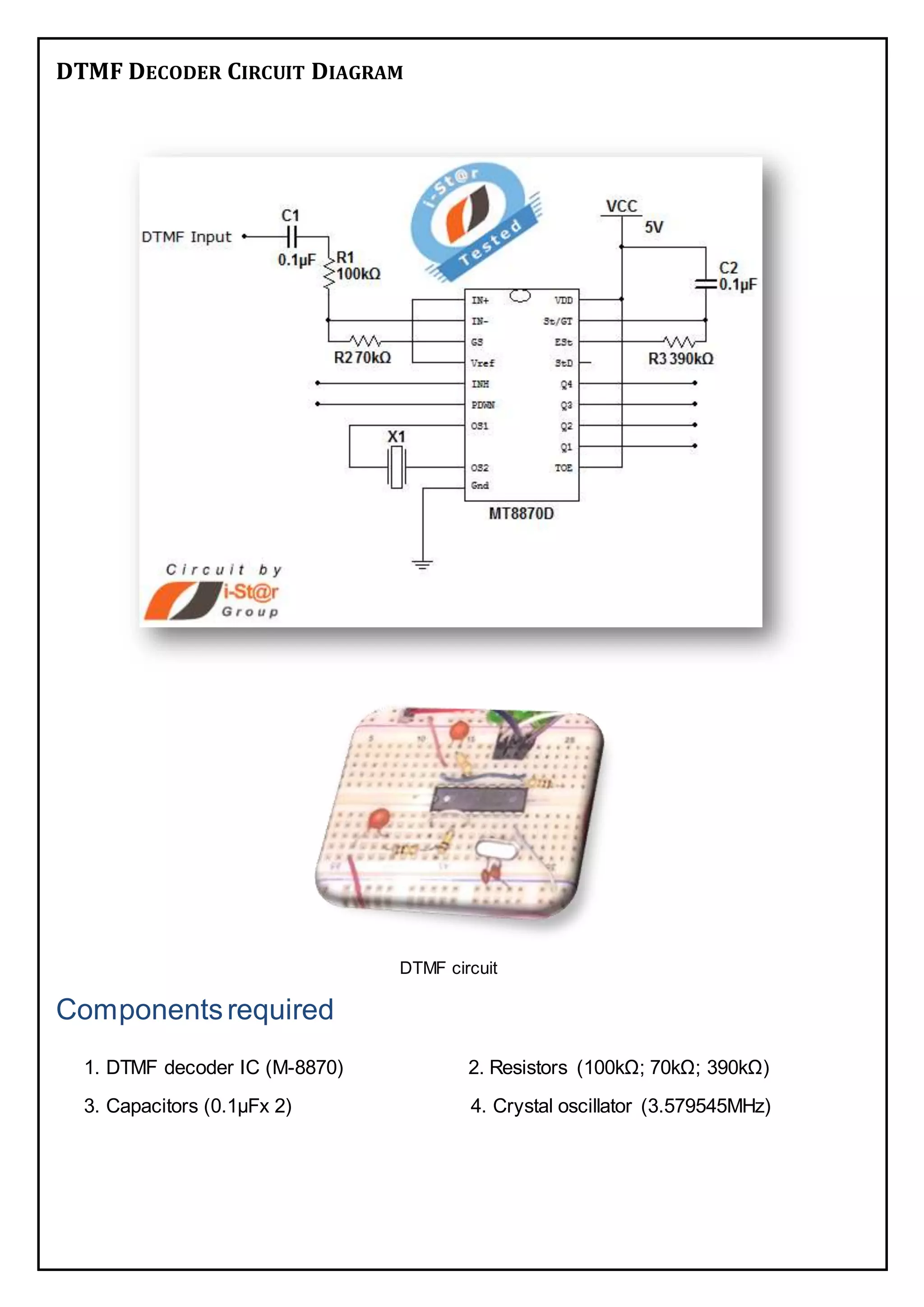
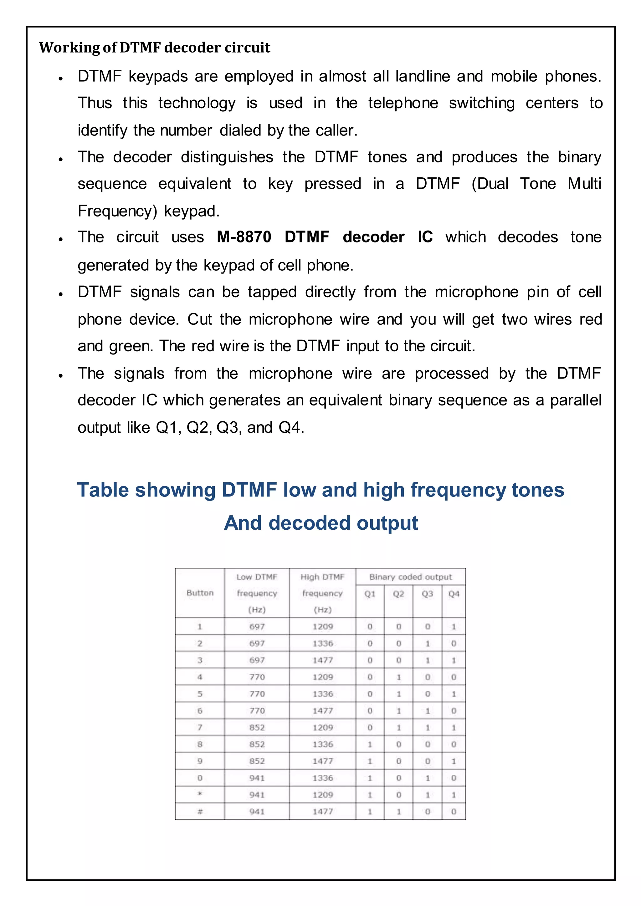
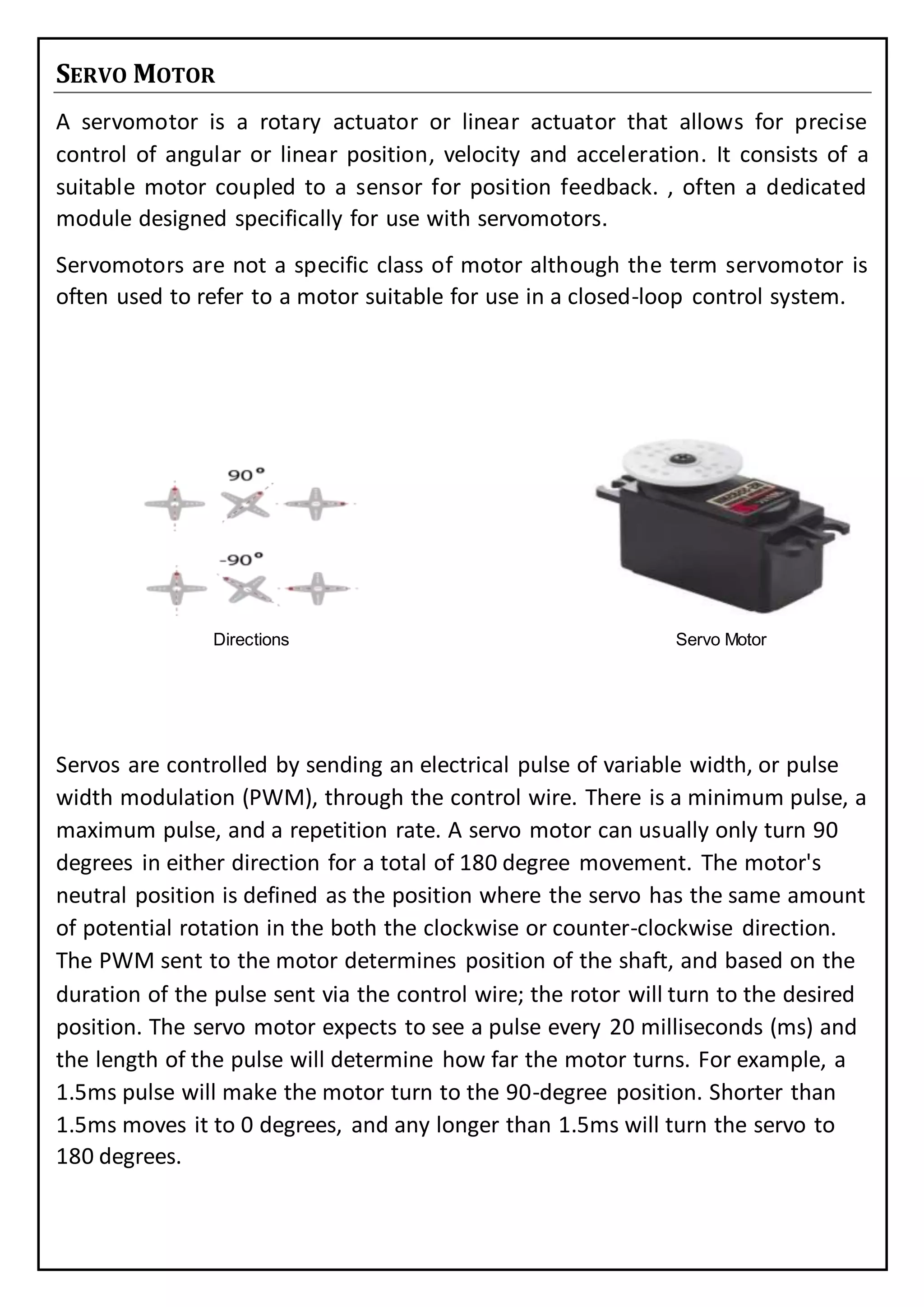
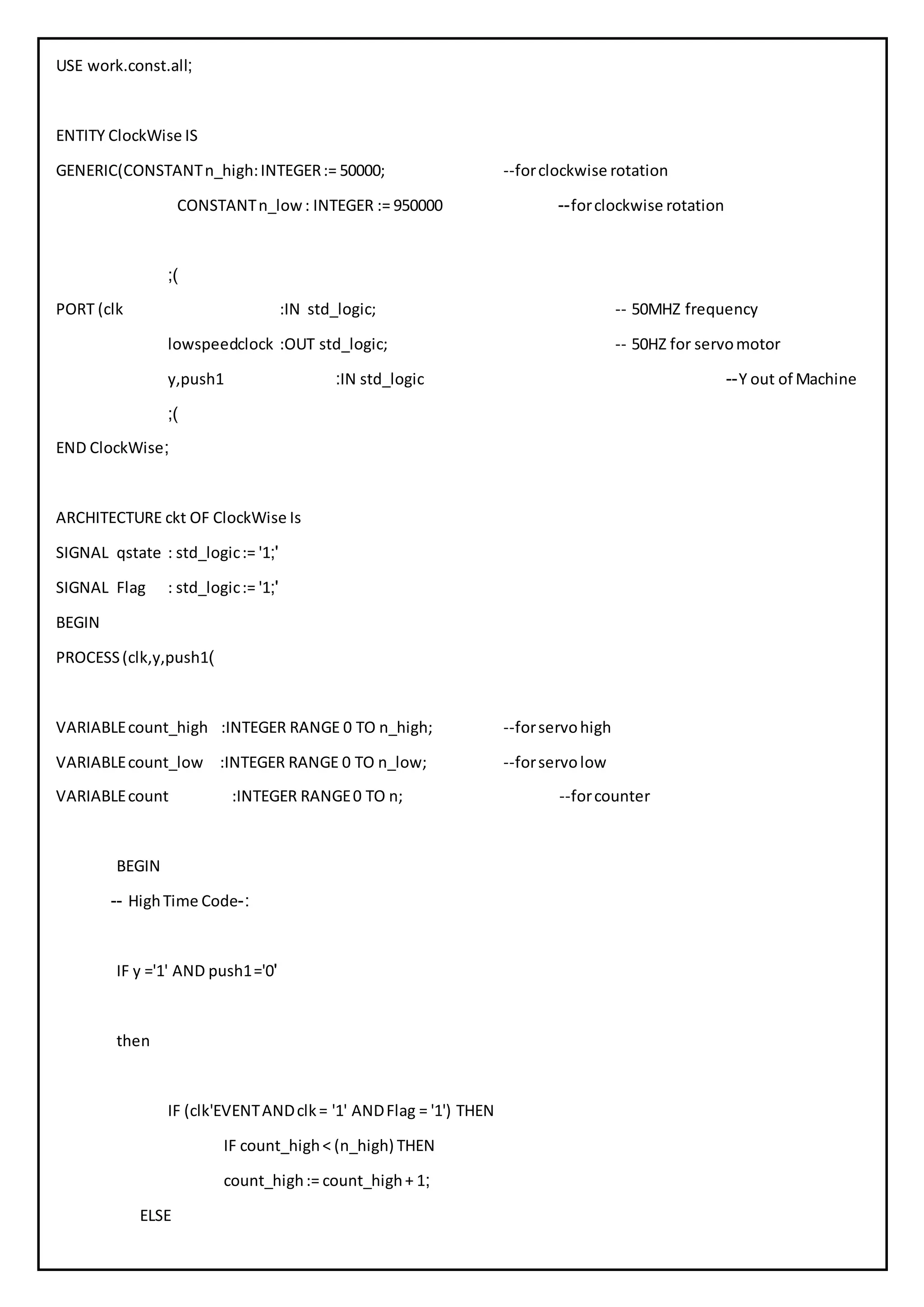
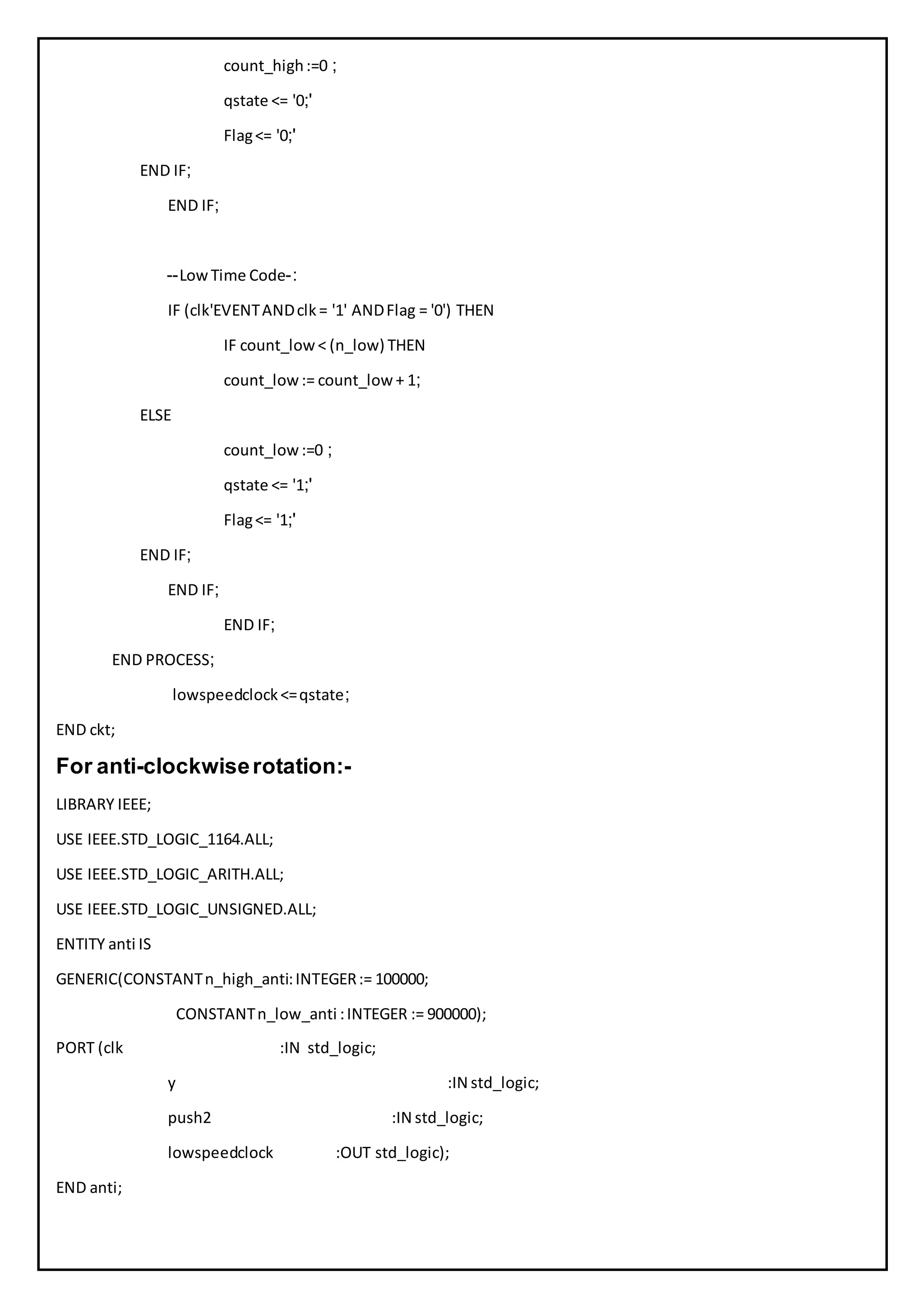
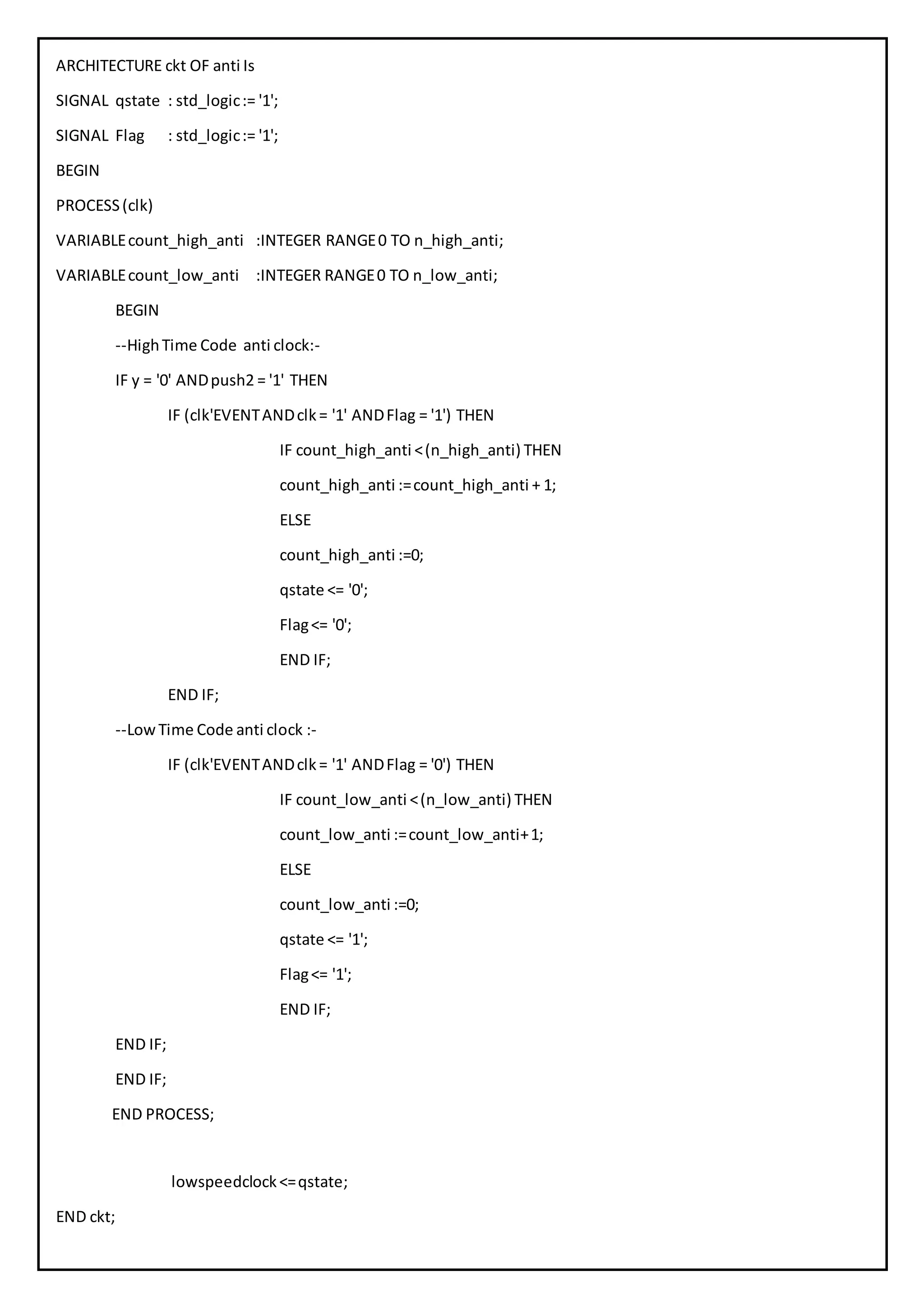
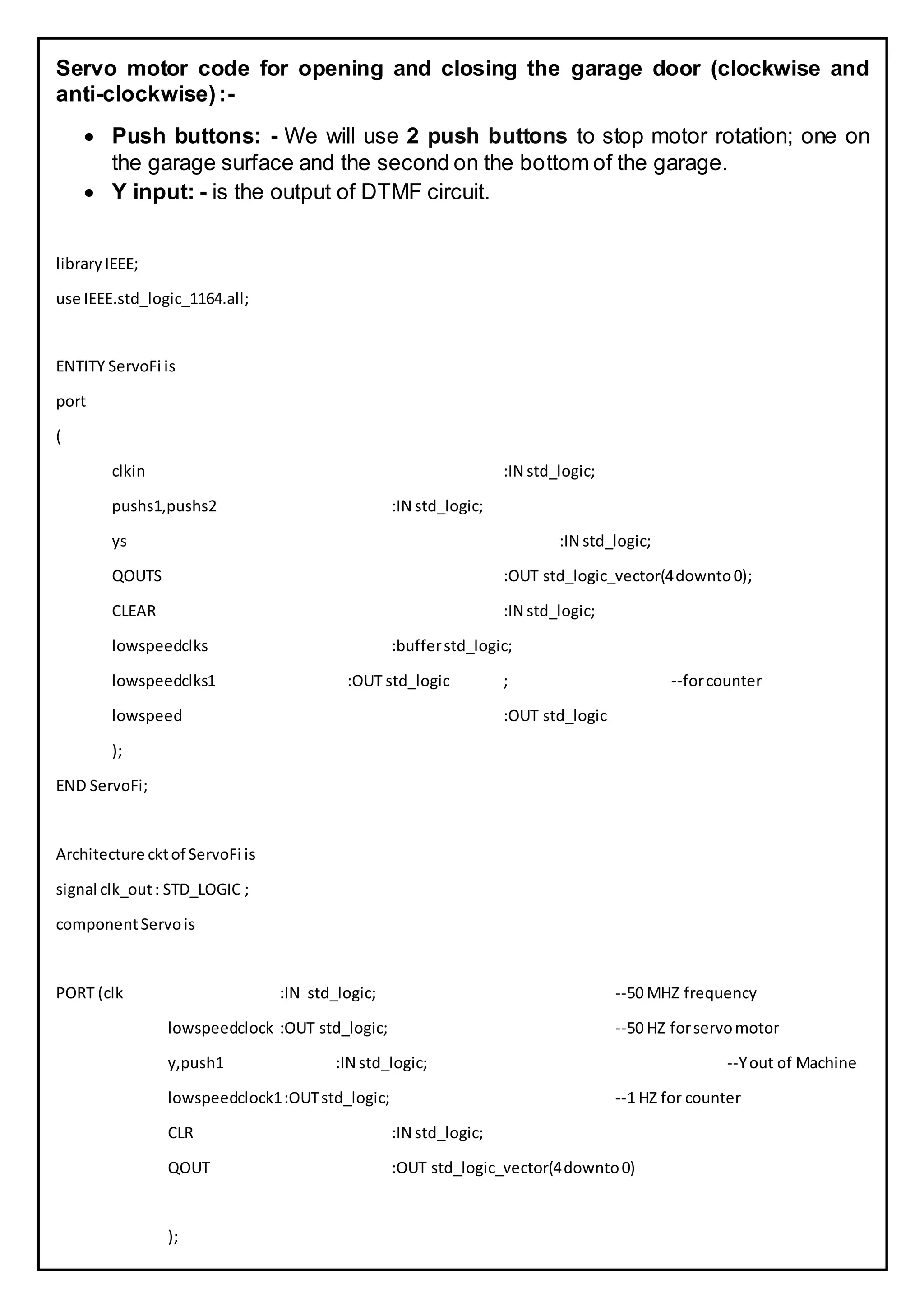
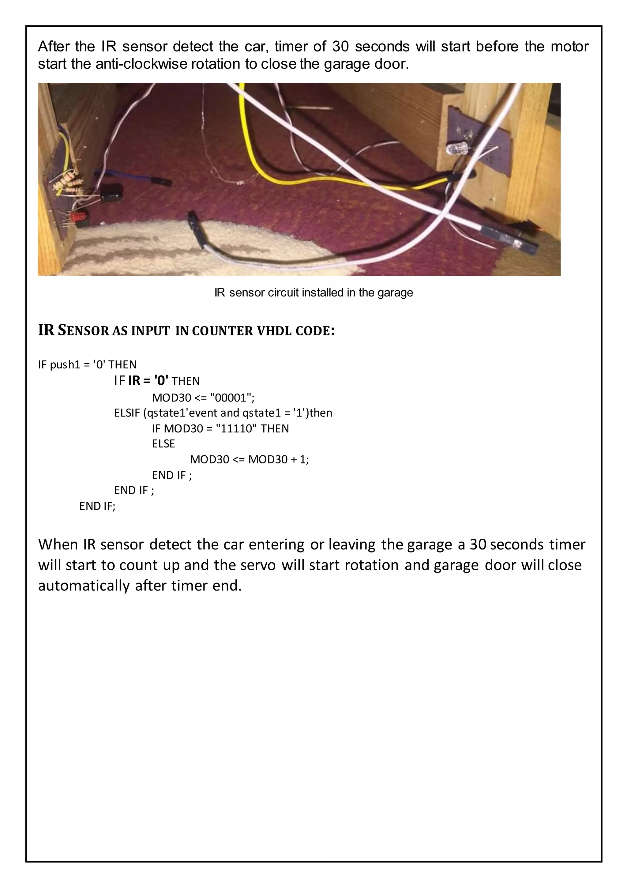
6/18/2016 Automatic Garage
System (AGS)
Using VHDL Programming Language
Automatic Garage System (AGS)
Using VHDL programming language
Suez Canal University
Faculty of Engineering
Electrical Engineering Department
Level 3
Submitted to: Dr/Mohamed Kkairy Shahin
Project Team
Amr Ashraf
Omar Fouad
Sherif said
Mahmoud Salah
Atef Nabil
Bassam Abdellah
Hassan Mohamed
Ahmed Nabil Ali
CONTENTS
Introduction......................................................................................................................4
Motivation ........................................................................................................................4
Project Components..........................................................................................................5
DE0 Altera kit....................................................................................................................5
DE0 Kit Components.......................................................................................................6
DTMF Circuit.....................................................................................................................6
DTMF Decoder Circuit Diagram.......................................................................................7
Working of DTMF decoder circuit.................................................................................8
DTMF Output VHDL Code.............................................................................................9
Servo Motor....................................................................................................................10
Servo Motor Control (VHDL Code).................................................................................11
IR Sensor.........................................................................................................................16
Principles of Operation.................................................................................................16
IR Sensor as input in counter vhdl code:........................................................................17
Counter...........................................................................................................................18
Up counters .................................................................................................................18
Description...................................................................................................................18
30 seconds counter Flow Chart.....................................................................................18
Counter vhdl code:-......................................................................................................19
References......................................................................................................................21
INTRODUCTION
In this age of digital technology, every device and its operation has become
digital based. Now with digital based door lock systems, it is easier
to control the door movement of the garage. The new automated door
lock system does not need a key to lock or unlock the door of the
garage. This digital door entry system is in fact controlled by cell-phone
which is actually performing the role of remote over here. The keyless
door remote is an electronic circuit based device .This remote
transmits DTMF signals via air to another device of the
system installed in the garage.
The keyless car remote can be operated from any corner of the world.
The working of this locking system is very simple .You just have to carry
the cell phone with yourself and you can control the locks from
anywhere without any problem. It works on the entry number. The owner
has to press that entry number on the cell phone for controlling the locking
system. The entry number and so is the remote device of an
automatic keyless system.
MOTIVATION
The cell phone security system takes this idea of keyless entry
and transforms it into a convenient, versatile security system that
utilizes cell phone technology and the landline telephone
network. By taking advantage of dual-tone multi-frequency signaling,
the security system has the ability to introduce two-levels of
security. The first level will be decoding the calling party’s
identification information while the second level would consist of the
user attempting a password entry over the phone. The system achieves a
secure, convenient, and automated form of security for a place of residence.
PROJECT COMPONENTS
DE0 Altera kit.
Garage Prototype.
Servo Motors.
DTMF System.
LEDs
Car Prototype.
IR Sensor.
DE0 ALTERA KIT
DE0 KIT COMPONENTS
Altera Cyclone® III 3C16 FPGA device
Altera Serial Configuration device – EPCS4
USB Blaster (on board) for programming and user API control; both JTAG and Active Serial
(AS) programming modes are supported
8-MbyteSDRAM
4-MbyteFlash memory
SD Card socket
3 pushbutton switches
10 toggle switches
10 green user LEDs
50-MHz oscillator for clock sources
VGA DAC (4-bitresistor network) with VGA-outconnector
RS-232 transceiver
PS/2 mouse/keyboard connector
Two 40-pin Expansion Headers
DTMF CIRCUIT
This DTMF (Dual Tone Multi Frequency) decoder circuit identifies the dial
tone from the telephone line and decodes the key pressed on the remote
telephone. Here for the detection of DTMF signaling, we are using the IC
MT8870DE which is a touch tone decoder IC. It decodes the input DTMF to 5
digital outputs. The M-8870 DTMF decoder IC uses a digital counting technique
to determine the frequencies of the limited tones and to verify that they
correspond to standard DTMF frequencies. The DTMF tone is a form of one way
communication between the dialer and the telephone exchange. The whole
communication consists of the touch tone initiator and the tone decoder or
detector. The decoded bits can be interfaced to a DE0 Altera kit for further
application (For example, automatic garage system.
DTMF DECODER CIRCUIT DIAGRAM
DTMF circuit
Componentsrequired
1. DTMF decoder IC (M-8870) 2. Resistors (100kΩ; 70kΩ; 390kΩ)
3. Capacitors (0.1µFx 2) 4. Crystal oscillator (3.579545MHz)
Working of DTMF decoder circuit
 DTMF keypads are employed in almost all landline and mobile phones.
Thus this technology is used in the telephone switching centers to
identify the number dialed by the caller.
 The decoder distinguishes the DTMF tones and produces the binary
sequence equivalent to key pressed in a DTMF (Dual Tone Multi
Frequency) keypad.
 The circuit uses M-8870 DTMF decoder IC which decodes tone
generated by the keypad of cell phone.
 DTMF signals can be tapped directly from the microphone pin of cell
phone device. Cut the microphone wire and you will get two wires red
and green. The red wire is the DTMF input to the circuit.
 The signals from the microphone wire are processed by the DTMF
decoder IC which generates an equivalent binary sequence as a parallel
output like Q1, Q2, Q3, and Q4.
Table showing DTMF low and high frequency tones
And decoded output
 There is an inbuilt Op amp present inside the M-8870 decoder IC. The
electrical signals from microphone pin are fed to inverting input of the Op
Amp via a series of resistance (100kΩ) and capacitance (0.1 µF).
 The non-inverting input of Op-amp is connected to a reference voltage
(pin4 -VREF). The voltage at VREF pin is Vcc/2.
 Pin 3 (GS) is the output of internal Op Amp, the feedback signal is given by
connecting the output pin (pin3- GS) to inverting input pin (pin2- IN-)
through a resistor (270kΩ).
 The output of Op Amp is passed through a pre filter, low group and high
group filters (filter networks). These filters contain switched capacitors to
divide DTMF tones into low and high group signals (High group filters
bypass the high frequencies whereas low group filter pass low
frequencies).
 Next processing sections inside the IC are frequency detector and code
detector circuits. Filtered frequency passed through these detectors.
 At last the four digit binary code is latched at the output of M-8870 DTMF
decoder IC.
DTMF Output VHDLCode
libraryIEEE;
use IEEE.std_logic_1164.all;
ENTITY dtmf is
port
( x :IN std_logic_vector(3downto0);
ys :OUT std_logic;
clk :IN std_logic
);
END dtmf;
Architecture cktof dtmf is
BEGIN
ys<= (NOT(x(3)))ANDx(2)ANDx(1)AND(NOT(x(0)));
END ckt;
SERVO MOTOR
A servomotor is a rotary actuator or linear actuator that allows for precise
control of angular or linear position, velocity and acceleration. It consists of a
suitable motor coupled to a sensor for position feedback. , often a dedicated
module designed specifically for use with servomotors.
Servomotors are not a specific class of motor although the term servomotor is
often used to refer to a motor suitable for use in a closed-loop control system.
Directions Servo Motor
Servos are controlled by sending an electrical pulse of variable width, or pulse
width modulation (PWM), through the control wire. There is a minimum pulse, a
maximum pulse, and a repetition rate. A servo motor can usually only turn 90
degrees in either direction for a total of 180 degree movement. The motor's
neutral position is defined as the position where the servo has the same amount
of potential rotation in the both the clockwise or counter-clockwise direction.
The PWM sent to the motor determines position of the shaft, and based on the
duration of the pulse sent via the control wire; the rotor will turn to the desired
position. The servo motor expects to see a pulse every 20 milliseconds (ms) and
the length of the pulse will determine how far the motor turns. For example, a
1.5ms pulse will make the motor turn to the 90-degree position. Shorter than
1.5ms moves it to 0 degrees, and any longer than 1.5ms will turn the servo to
180 degrees.
Positions of Rotation
When these servos are commanded to move, they will move to the position and
hold that position. If an external force pushes against the servo while the servo
is holding a position, the servo will resist from moving out of that position. The
maximum amount of force the servo can exert is called the torque rating of the
servo. Servos will not hold their position forever though; the position pulse must
be repeated to instruct the servo to stay in position.
SERVO MOTOR CONTROL (VHDL CODE)
Servo motor which is used to open or close the garage door, will rotate 180°
clockwise. And when hit a bush button the motor will stop rotation and if IR
sensor detect the car, a 30 seconds timer will start and after the 30 sec the
motor will start rotating anti-clockwise to close the garage door .
VHDL Code:
FOR CLOCKWISE ROTATION:-
PACKAGEconstIS
CONSTANTnumber_of_bits :INTEGER:=25000000; --forclock
CONSTANTn: INTEGER :=number_of_bits -1;
END const;
LIBRARY IEEE;
USE IEEE.STD_LOGIC_1164.ALL;
USE IEEE.STD_LOGIC_ARITH.ALL;
USE IEEE.STD_LOGIC_UNSIGNED.ALL;
USE work.const.all;
ENTITY ClockWise IS
GENERIC(CONSTANTn_high:INTEGER:= 50000; --forclockwise rotation
CONSTANTn_low: INTEGER := 950000 --forclockwise rotation
;)
PORT (clk :IN std_logic; -- 00MHZ frequency
lowspeedclock :OUT std_logic; -- 00HZ for servomotor
y,push1 :IN std_logic --Y out of Machine
;)
END ClockWise;
ARCHITECTURE ckt OF ClockWise Is
SIGNAL qstate : std_logic:= '1;'
SIGNAL Flag : std_logic:= '1;'
BEGIN
PROCESS(clk,y,push1)
VARIABLEcount_high :INTEGER RANGE 0 TO n_high; --forservohigh
VARIABLEcount_low :INTEGER RANGE 0 TO n_low; --forservolow
VARIABLEcount :INTEGER RANGE0 TO n; --forcounter
BEGIN
-- HighTime Code :-
IF y ='1' AND push1='0'
then
IF (clk'EVENTANDclk= '1' ANDFlag = '1') THEN
IF count_high< (n_high) THEN
count_high:= count_high+ 1;
ELSE
count_high:=0 ;
qstate <= '0;'
Flag<= '0;'
END IF;
END IF;
--LowTime Code :-
IF (clk'EVENTANDclk= '1' ANDFlag = '0') THEN
IF count_low< (n_low) THEN
count_low:= count_low + 1;
ELSE
count_low:=0 ;
qstate <= '1;'
Flag<= '1;'
END IF;
END IF;
END IF;
END PROCESS;
lowspeedclock<=qstate;
END ckt;
For anti-clockwiserotation:-
LIBRARY IEEE;
USE IEEE.STD_LOGIC_1164.ALL;
USE IEEE.STD_LOGIC_ARITH.ALL;
USE IEEE.STD_LOGIC_UNSIGNED.ALL;
ENTITY anti IS
GENERIC(CONSTANTn_high_anti:INTEGER:= 100000;
CONSTANTn_low_anti :INTEGER := 900000);
PORT (clk :IN std_logic;
y :IN std_logic;
push2 :IN std_logic;
lowspeedclock :OUT std_logic);
END anti;
ARCHITECTURE ckt OF anti Is
SIGNAL qstate : std_logic:= '1';
SIGNAL Flag : std_logic:= '1';
BEGIN
PROCESS(clk)
VARIABLEcount_high_anti :INTEGER RANGE0 TO n_high_anti;
VARIABLEcount_low_anti :INTEGER RANGE0 TO n_low_anti;
BEGIN
--HighTime Code anti clock:-
IF y = '0' ANDpush2 = '1' THEN
IF (clk'EVENTANDclk= '1' ANDFlag = '1') THEN
IF count_high_anti <(n_high_anti) THEN
count_high_anti :=count_high_anti + 1;
ELSE
count_high_anti :=0;
qstate <= '0';
Flag<= '0';
END IF;
END IF;
--LowTime Code anti clock :-
IF (clk'EVENTANDclk= '1' ANDFlag = '0') THEN
IF count_low_anti <(n_low_anti) THEN
count_low_anti :=count_low_anti+1;
ELSE
count_low_anti :=0;
qstate <= '1';
Flag<= '1';
END IF;
END IF;
END IF;
END PROCESS;
lowspeedclock<=qstate;
END ckt;
Servo motor code for opening and closing the garage door (clockwise and
anti-clockwise):-
 Push buttons: - We will use 2 push buttons to stop motor rotation; one on
the garage surface and the second on the bottom of the garage.
 Y input: - is the output of DTMF circuit.
libraryIEEE;
use IEEE.std_logic_1164.all;
ENTITY ServoFi is
port
(
clkin :IN std_logic;
pushs1,pushs2 :IN std_logic;
ys :IN std_logic;
QOUTS :OUT std_logic_vector(4downto0);
CLEAR :IN std_logic;
lowspeedclks :bufferstd_logic;
lowspeedclks1 :OUT std_logic ; --forcounter
lowspeed :OUT std_logic
);
END ServoFi;
Architecture cktof ServoFi is
signal clk_out: STD_LOGIC ;
componentServois
PORT (clk :IN std_logic; --50 MHZ frequency
lowspeedclock :OUT std_logic; --50 HZ forservomotor
y,push1 :IN std_logic; --Yout of Machine
lowspeedclock1:OUTstd_logic; --1 HZ for counter
CLR :IN std_logic;
QOUT :OUT std_logic_vector(4downto0)
);
END component;
componentanticlkis
PORT (clk :IN std_logic;
push2,y :IN std_logic;
lowspeedclock :OUT std_logic);
END Component;
Begin
CLKWISE : Servoportmap (clkin,lowspeedclks,ys,pushs1,lowspeedclks1,clear,QOUTS) ;
ANTI : anticlkportmap (clkin,pushs2,ys,lowspeed);
END ckt;
IR SENSOR
PRINCIPLES OF OPERATION
IRSensors work by using a specific light sensor to detect a select light wavelength in the
Infra-Red (IR) spectrum. By using an LED which produces light at the same wavelength as
what the sensor is looking for, you can look at the intensity of the received light. When an
object (User’s car) tis closeto the sensor, the light fromthe LED bounces off the object and
into the light sensor. This results in a large jump in the intensity, which we already know
can be detected using a threshold.
Operation Of an IR Sensor
After the IR sensor detect the car, timer of 30 seconds will start before the motor
start the anti-clockwise rotation to close the garage door.
IR sensor circuit installed in the garage
IR SENSOR AS INPUT IN COUNTER VHDL CODE:
IF push1 = '0' THEN
IF IR = '0' THEN
MOD30 <= "00001";
ELSIF (qstate1'event and qstate1 = '1')then
IF MOD30 = "11110" THEN
ELSE
MOD30 <= MOD30 + 1;
END IF ;
END IF ;
END IF;
When IR sensor detect the car entering or leaving the garage a 30 seconds timer
will start to count up and the servo will start rotation and garage door will close
automatically after timer end.
COUNTER
A counter is a device which stores the number of times a particular event or process has
occurred, often in relationship to a clock signal. There are two types of counters:
 up counters
 down counters
UP COUNTERS
Each of the higher-order flip-flops are made ready to toggle (both J and K inputs "high") if
the Q outputs of all previous flip-flops are "high." Otherwise, theJ and K inputs for that flip-
flop will both be "low," placing it into the "latch" mode where it will maintain its present
output state at the next clock pulse. Since the first(LSB) flip-flop needs to toggle at every
clock pulse, its J and K inputs are connected to Vcc or Vdd, where they will be "high" all the
time.
DESCRIPTION
In this programan up counter has a 1- bit input and a 4- bit output. Additional control
signals may be added such as enable. The output of the multiplexers depends on the level
of the select line.
30 SECONDS COUNTER FLOW CHART
COUNTER VHDL CODE:-
PACKAGEconstClkIS
CONSTANTnumber_of_bits :INTEGER:=25000000; --forclock
CONSTANTn: INTEGER :=number_of_bits -1;
END constClk;
LIBRARY IEEE;
USE IEEE.STD_LOGIC_1164.ALL;
USE IEEE.STD_LOGIC_ARITH.ALL;
USE IEEE.STD_LOGIC_UNSIGNED.ALL;
USE work.constClk.all;
ENTITY CounterIS
GENERIC(CONSTANTn_high:INTEGER:= 50000; --forclockwise rotation
CONSTANTn_low : INTEGER := 950000 --
for clockwise rotation
;)
PORT (clk :IN std_logic; -- 00
MHZ frequency
push1 :IN std_logic;
--Yout of Machine
push2 :IN std_logic;
lowspeedclock1:OUTstd_logic;
-- 1HZ forcounter
QOUT :OUT std_logic_vector(4
downto0;)
clr :IN std_logic;
IR :IN std_logic;
Over30 :BUFFER std_logic
;)
END Counter;
ARCHITECTURE ckt OF CounterIs
SIGNAL qstate1 :std_logic;
SIGNAL MOD30 : std_logic_vector(4downto 0;)
BEGIN
PROCESS(clk,push1,qstate1)
VARIABLEcount :INTEGER RANGE0 TO n; --forcounter
BEGIN
IF (clk'EVENTANDclk= '1') THEN
IF count< (n+1) THEN
count := count + 1;
ELSE
count :=0 ;
qstate1<= NOT qstate1;
END IF;
END IF;
IF push1= '1' THEN
IF ir = '0' THEN
MOD30 <= "00001;"
ELSIF (qstate1'eventandqstate1='1')then
IF MOD30 = "11110" THEN
OVER30 <='1;'
ELSE
MOD30 <= MOD30 + 1;
END IF;
END IF;
END IF;
IF MOD30 = "11110" AND push2= '1' THEN
OVER30 <='0;'
MOD30 <= "00001;"
END IF;
END PROCESS;
QOUT <= MOD30;
lowspeedclock1<=qstate1;
END ckt;
REFERENCES
1) DE0 User manual (pdf).
2) Scripd.com(Website).
3) IR Sensor Wikipedia (Website).
4) Reportabout DTMF (Article).
5) DTMF Wikipedia (Website).
6) Counters Wikipedia (Website).
7) Altera.com (Website)

Automatic Garage System using VHDL

  • 1.
    6/18/2016 Automatic Garage System(AGS) Using VHDL Programming Language
  • 2.
    Automatic Garage System(AGS) Using VHDL programming language Suez Canal University Faculty of Engineering Electrical Engineering Department Level 3 Submitted to: Dr/Mohamed Kkairy Shahin
  • 3.
    Project Team Amr Ashraf OmarFouad Sherif said Mahmoud Salah Atef Nabil Bassam Abdellah Hassan Mohamed Ahmed Nabil Ali
  • 4.
    CONTENTS Introduction......................................................................................................................4 Motivation ........................................................................................................................4 Project Components..........................................................................................................5 DE0Altera kit....................................................................................................................5 DE0 Kit Components.......................................................................................................6 DTMF Circuit.....................................................................................................................6 DTMF Decoder Circuit Diagram.......................................................................................7 Working of DTMF decoder circuit.................................................................................8 DTMF Output VHDL Code.............................................................................................9 Servo Motor....................................................................................................................10 Servo Motor Control (VHDL Code).................................................................................11 IR Sensor.........................................................................................................................16 Principles of Operation.................................................................................................16 IR Sensor as input in counter vhdl code:........................................................................17 Counter...........................................................................................................................18 Up counters .................................................................................................................18 Description...................................................................................................................18 30 seconds counter Flow Chart.....................................................................................18 Counter vhdl code:-......................................................................................................19 References......................................................................................................................21
  • 5.
    INTRODUCTION In this ageof digital technology, every device and its operation has become digital based. Now with digital based door lock systems, it is easier to control the door movement of the garage. The new automated door lock system does not need a key to lock or unlock the door of the garage. This digital door entry system is in fact controlled by cell-phone which is actually performing the role of remote over here. The keyless door remote is an electronic circuit based device .This remote transmits DTMF signals via air to another device of the system installed in the garage. The keyless car remote can be operated from any corner of the world. The working of this locking system is very simple .You just have to carry the cell phone with yourself and you can control the locks from anywhere without any problem. It works on the entry number. The owner has to press that entry number on the cell phone for controlling the locking system. The entry number and so is the remote device of an automatic keyless system. MOTIVATION The cell phone security system takes this idea of keyless entry and transforms it into a convenient, versatile security system that utilizes cell phone technology and the landline telephone network. By taking advantage of dual-tone multi-frequency signaling, the security system has the ability to introduce two-levels of security. The first level will be decoding the calling party’s identification information while the second level would consist of the user attempting a password entry over the phone. The system achieves a secure, convenient, and automated form of security for a place of residence.
  • 6.
    PROJECT COMPONENTS DE0 Alterakit. Garage Prototype. Servo Motors. DTMF System. LEDs Car Prototype. IR Sensor. DE0 ALTERA KIT
  • 7.
    DE0 KIT COMPONENTS AlteraCyclone® III 3C16 FPGA device Altera Serial Configuration device – EPCS4 USB Blaster (on board) for programming and user API control; both JTAG and Active Serial (AS) programming modes are supported 8-MbyteSDRAM 4-MbyteFlash memory SD Card socket 3 pushbutton switches 10 toggle switches 10 green user LEDs 50-MHz oscillator for clock sources VGA DAC (4-bitresistor network) with VGA-outconnector RS-232 transceiver PS/2 mouse/keyboard connector Two 40-pin Expansion Headers DTMF CIRCUIT This DTMF (Dual Tone Multi Frequency) decoder circuit identifies the dial tone from the telephone line and decodes the key pressed on the remote telephone. Here for the detection of DTMF signaling, we are using the IC MT8870DE which is a touch tone decoder IC. It decodes the input DTMF to 5 digital outputs. The M-8870 DTMF decoder IC uses a digital counting technique to determine the frequencies of the limited tones and to verify that they correspond to standard DTMF frequencies. The DTMF tone is a form of one way communication between the dialer and the telephone exchange. The whole communication consists of the touch tone initiator and the tone decoder or detector. The decoded bits can be interfaced to a DE0 Altera kit for further application (For example, automatic garage system.
  • 8.
    DTMF DECODER CIRCUITDIAGRAM DTMF circuit Componentsrequired 1. DTMF decoder IC (M-8870) 2. Resistors (100kΩ; 70kΩ; 390kΩ) 3. Capacitors (0.1µFx 2) 4. Crystal oscillator (3.579545MHz)
  • 9.
    Working of DTMFdecoder circuit  DTMF keypads are employed in almost all landline and mobile phones. Thus this technology is used in the telephone switching centers to identify the number dialed by the caller.  The decoder distinguishes the DTMF tones and produces the binary sequence equivalent to key pressed in a DTMF (Dual Tone Multi Frequency) keypad.  The circuit uses M-8870 DTMF decoder IC which decodes tone generated by the keypad of cell phone.  DTMF signals can be tapped directly from the microphone pin of cell phone device. Cut the microphone wire and you will get two wires red and green. The red wire is the DTMF input to the circuit.  The signals from the microphone wire are processed by the DTMF decoder IC which generates an equivalent binary sequence as a parallel output like Q1, Q2, Q3, and Q4. Table showing DTMF low and high frequency tones And decoded output
  • 10.
     There isan inbuilt Op amp present inside the M-8870 decoder IC. The electrical signals from microphone pin are fed to inverting input of the Op Amp via a series of resistance (100kΩ) and capacitance (0.1 µF).  The non-inverting input of Op-amp is connected to a reference voltage (pin4 -VREF). The voltage at VREF pin is Vcc/2.  Pin 3 (GS) is the output of internal Op Amp, the feedback signal is given by connecting the output pin (pin3- GS) to inverting input pin (pin2- IN-) through a resistor (270kΩ).  The output of Op Amp is passed through a pre filter, low group and high group filters (filter networks). These filters contain switched capacitors to divide DTMF tones into low and high group signals (High group filters bypass the high frequencies whereas low group filter pass low frequencies).  Next processing sections inside the IC are frequency detector and code detector circuits. Filtered frequency passed through these detectors.  At last the four digit binary code is latched at the output of M-8870 DTMF decoder IC. DTMF Output VHDLCode libraryIEEE; use IEEE.std_logic_1164.all; ENTITY dtmf is port ( x :IN std_logic_vector(3downto0); ys :OUT std_logic; clk :IN std_logic ); END dtmf; Architecture cktof dtmf is BEGIN ys<= (NOT(x(3)))ANDx(2)ANDx(1)AND(NOT(x(0))); END ckt;
  • 11.
    SERVO MOTOR A servomotoris a rotary actuator or linear actuator that allows for precise control of angular or linear position, velocity and acceleration. It consists of a suitable motor coupled to a sensor for position feedback. , often a dedicated module designed specifically for use with servomotors. Servomotors are not a specific class of motor although the term servomotor is often used to refer to a motor suitable for use in a closed-loop control system. Directions Servo Motor Servos are controlled by sending an electrical pulse of variable width, or pulse width modulation (PWM), through the control wire. There is a minimum pulse, a maximum pulse, and a repetition rate. A servo motor can usually only turn 90 degrees in either direction for a total of 180 degree movement. The motor's neutral position is defined as the position where the servo has the same amount of potential rotation in the both the clockwise or counter-clockwise direction. The PWM sent to the motor determines position of the shaft, and based on the duration of the pulse sent via the control wire; the rotor will turn to the desired position. The servo motor expects to see a pulse every 20 milliseconds (ms) and the length of the pulse will determine how far the motor turns. For example, a 1.5ms pulse will make the motor turn to the 90-degree position. Shorter than 1.5ms moves it to 0 degrees, and any longer than 1.5ms will turn the servo to 180 degrees.
  • 12.
    Positions of Rotation Whenthese servos are commanded to move, they will move to the position and hold that position. If an external force pushes against the servo while the servo is holding a position, the servo will resist from moving out of that position. The maximum amount of force the servo can exert is called the torque rating of the servo. Servos will not hold their position forever though; the position pulse must be repeated to instruct the servo to stay in position. SERVO MOTOR CONTROL (VHDL CODE) Servo motor which is used to open or close the garage door, will rotate 180° clockwise. And when hit a bush button the motor will stop rotation and if IR sensor detect the car, a 30 seconds timer will start and after the 30 sec the motor will start rotating anti-clockwise to close the garage door . VHDL Code: FOR CLOCKWISE ROTATION:- PACKAGEconstIS CONSTANTnumber_of_bits :INTEGER:=25000000; --forclock CONSTANTn: INTEGER :=number_of_bits -1; END const; LIBRARY IEEE; USE IEEE.STD_LOGIC_1164.ALL; USE IEEE.STD_LOGIC_ARITH.ALL; USE IEEE.STD_LOGIC_UNSIGNED.ALL;
  • 13.
    USE work.const.all; ENTITY ClockWiseIS GENERIC(CONSTANTn_high:INTEGER:= 50000; --forclockwise rotation CONSTANTn_low: INTEGER := 950000 --forclockwise rotation ;) PORT (clk :IN std_logic; -- 00MHZ frequency lowspeedclock :OUT std_logic; -- 00HZ for servomotor y,push1 :IN std_logic --Y out of Machine ;) END ClockWise; ARCHITECTURE ckt OF ClockWise Is SIGNAL qstate : std_logic:= '1;' SIGNAL Flag : std_logic:= '1;' BEGIN PROCESS(clk,y,push1) VARIABLEcount_high :INTEGER RANGE 0 TO n_high; --forservohigh VARIABLEcount_low :INTEGER RANGE 0 TO n_low; --forservolow VARIABLEcount :INTEGER RANGE0 TO n; --forcounter BEGIN -- HighTime Code :- IF y ='1' AND push1='0' then IF (clk'EVENTANDclk= '1' ANDFlag = '1') THEN IF count_high< (n_high) THEN count_high:= count_high+ 1; ELSE
  • 14.
    count_high:=0 ; qstate <='0;' Flag<= '0;' END IF; END IF; --LowTime Code :- IF (clk'EVENTANDclk= '1' ANDFlag = '0') THEN IF count_low< (n_low) THEN count_low:= count_low + 1; ELSE count_low:=0 ; qstate <= '1;' Flag<= '1;' END IF; END IF; END IF; END PROCESS; lowspeedclock<=qstate; END ckt; For anti-clockwiserotation:- LIBRARY IEEE; USE IEEE.STD_LOGIC_1164.ALL; USE IEEE.STD_LOGIC_ARITH.ALL; USE IEEE.STD_LOGIC_UNSIGNED.ALL; ENTITY anti IS GENERIC(CONSTANTn_high_anti:INTEGER:= 100000; CONSTANTn_low_anti :INTEGER := 900000); PORT (clk :IN std_logic; y :IN std_logic; push2 :IN std_logic; lowspeedclock :OUT std_logic); END anti;
  • 15.
    ARCHITECTURE ckt OFanti Is SIGNAL qstate : std_logic:= '1'; SIGNAL Flag : std_logic:= '1'; BEGIN PROCESS(clk) VARIABLEcount_high_anti :INTEGER RANGE0 TO n_high_anti; VARIABLEcount_low_anti :INTEGER RANGE0 TO n_low_anti; BEGIN --HighTime Code anti clock:- IF y = '0' ANDpush2 = '1' THEN IF (clk'EVENTANDclk= '1' ANDFlag = '1') THEN IF count_high_anti <(n_high_anti) THEN count_high_anti :=count_high_anti + 1; ELSE count_high_anti :=0; qstate <= '0'; Flag<= '0'; END IF; END IF; --LowTime Code anti clock :- IF (clk'EVENTANDclk= '1' ANDFlag = '0') THEN IF count_low_anti <(n_low_anti) THEN count_low_anti :=count_low_anti+1; ELSE count_low_anti :=0; qstate <= '1'; Flag<= '1'; END IF; END IF; END IF; END PROCESS; lowspeedclock<=qstate; END ckt;
  • 16.
    Servo motor codefor opening and closing the garage door (clockwise and anti-clockwise):-  Push buttons: - We will use 2 push buttons to stop motor rotation; one on the garage surface and the second on the bottom of the garage.  Y input: - is the output of DTMF circuit. libraryIEEE; use IEEE.std_logic_1164.all; ENTITY ServoFi is port ( clkin :IN std_logic; pushs1,pushs2 :IN std_logic; ys :IN std_logic; QOUTS :OUT std_logic_vector(4downto0); CLEAR :IN std_logic; lowspeedclks :bufferstd_logic; lowspeedclks1 :OUT std_logic ; --forcounter lowspeed :OUT std_logic ); END ServoFi; Architecture cktof ServoFi is signal clk_out: STD_LOGIC ; componentServois PORT (clk :IN std_logic; --50 MHZ frequency lowspeedclock :OUT std_logic; --50 HZ forservomotor y,push1 :IN std_logic; --Yout of Machine lowspeedclock1:OUTstd_logic; --1 HZ for counter CLR :IN std_logic; QOUT :OUT std_logic_vector(4downto0) );
  • 17.
    END component; componentanticlkis PORT (clk:IN std_logic; push2,y :IN std_logic; lowspeedclock :OUT std_logic); END Component; Begin CLKWISE : Servoportmap (clkin,lowspeedclks,ys,pushs1,lowspeedclks1,clear,QOUTS) ; ANTI : anticlkportmap (clkin,pushs2,ys,lowspeed); END ckt; IR SENSOR PRINCIPLES OF OPERATION IRSensors work by using a specific light sensor to detect a select light wavelength in the Infra-Red (IR) spectrum. By using an LED which produces light at the same wavelength as what the sensor is looking for, you can look at the intensity of the received light. When an object (User’s car) tis closeto the sensor, the light fromthe LED bounces off the object and into the light sensor. This results in a large jump in the intensity, which we already know can be detected using a threshold. Operation Of an IR Sensor
  • 18.
    After the IRsensor detect the car, timer of 30 seconds will start before the motor start the anti-clockwise rotation to close the garage door. IR sensor circuit installed in the garage IR SENSOR AS INPUT IN COUNTER VHDL CODE: IF push1 = '0' THEN IF IR = '0' THEN MOD30 <= "00001"; ELSIF (qstate1'event and qstate1 = '1')then IF MOD30 = "11110" THEN ELSE MOD30 <= MOD30 + 1; END IF ; END IF ; END IF; When IR sensor detect the car entering or leaving the garage a 30 seconds timer will start to count up and the servo will start rotation and garage door will close automatically after timer end.
  • 19.
    COUNTER A counter isa device which stores the number of times a particular event or process has occurred, often in relationship to a clock signal. There are two types of counters:  up counters  down counters UP COUNTERS Each of the higher-order flip-flops are made ready to toggle (both J and K inputs "high") if the Q outputs of all previous flip-flops are "high." Otherwise, theJ and K inputs for that flip- flop will both be "low," placing it into the "latch" mode where it will maintain its present output state at the next clock pulse. Since the first(LSB) flip-flop needs to toggle at every clock pulse, its J and K inputs are connected to Vcc or Vdd, where they will be "high" all the time. DESCRIPTION In this programan up counter has a 1- bit input and a 4- bit output. Additional control signals may be added such as enable. The output of the multiplexers depends on the level of the select line. 30 SECONDS COUNTER FLOW CHART
  • 20.
    COUNTER VHDL CODE:- PACKAGEconstClkIS CONSTANTnumber_of_bits:INTEGER:=25000000; --forclock CONSTANTn: INTEGER :=number_of_bits -1; END constClk; LIBRARY IEEE; USE IEEE.STD_LOGIC_1164.ALL; USE IEEE.STD_LOGIC_ARITH.ALL; USE IEEE.STD_LOGIC_UNSIGNED.ALL; USE work.constClk.all; ENTITY CounterIS GENERIC(CONSTANTn_high:INTEGER:= 50000; --forclockwise rotation CONSTANTn_low : INTEGER := 950000 -- for clockwise rotation ;) PORT (clk :IN std_logic; -- 00 MHZ frequency push1 :IN std_logic; --Yout of Machine push2 :IN std_logic; lowspeedclock1:OUTstd_logic; -- 1HZ forcounter QOUT :OUT std_logic_vector(4 downto0;) clr :IN std_logic; IR :IN std_logic; Over30 :BUFFER std_logic ;) END Counter; ARCHITECTURE ckt OF CounterIs SIGNAL qstate1 :std_logic; SIGNAL MOD30 : std_logic_vector(4downto 0;)
  • 21.
    BEGIN PROCESS(clk,push1,qstate1) VARIABLEcount :INTEGER RANGE0TO n; --forcounter BEGIN IF (clk'EVENTANDclk= '1') THEN IF count< (n+1) THEN count := count + 1; ELSE count :=0 ; qstate1<= NOT qstate1; END IF; END IF; IF push1= '1' THEN IF ir = '0' THEN MOD30 <= "00001;" ELSIF (qstate1'eventandqstate1='1')then IF MOD30 = "11110" THEN OVER30 <='1;' ELSE MOD30 <= MOD30 + 1; END IF; END IF; END IF; IF MOD30 = "11110" AND push2= '1' THEN OVER30 <='0;' MOD30 <= "00001;" END IF; END PROCESS; QOUT <= MOD30; lowspeedclock1<=qstate1; END ckt;
  • 22.
    REFERENCES 1) DE0 Usermanual (pdf). 2) Scripd.com(Website). 3) IR Sensor Wikipedia (Website). 4) Reportabout DTMF (Article). 5) DTMF Wikipedia (Website). 6) Counters Wikipedia (Website). 7) Altera.com (Website)