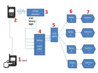
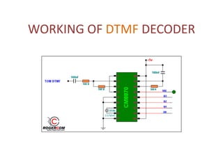
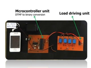
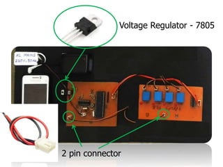
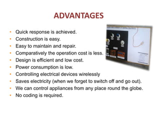
CONTENTS
 Introduction
 Block diagram
 DTMF – working
 Components used
 Working
 Software used
 Advantages
 Applications
INTRODUCTION
• What had been thought impossible at one time was achieved by
man.
• As technology advanced man was able to control everything from
one place.
• Controlling electrical appliances with mobile is one of the examples.
• This makes the use of DTMF(Dual Tone Multi Frequency) technique.
• The DTMF Decoder circuit is made using M8870 Decoder IC.
• Just connect your cell phone headset (headphone) jack to the
mobile phone and then mobile control electrical appliances and
electrical equipment via DTMF key pad of your cell phone.
BLOCK
DIAGRAM
DTMF
decoder
Micro
-
contr
oller
Relay
1
Relay
2
Relay
3
Relay
4
Appliance
2
Appliance
3
Appliance
1
Appliance
4
4 bit
binary
digit
1input
2
3
4
5
6
ULN
2803
7
DTMF keypad frequencies
DUAL TONE – every button on keypad is characterised
by two different tones
MULTI FREQ.- because it use a mixture of two pure tone
(pure sine wave) sounds
Hz 1209 1336 1477
697 1 2 3
770 4 5 6
852 7 8 9
941 * 0 #
WORKING OF DTMF DECODER
KEYPAD TONE DECODING
COMPONENTS USED
Transformer &
Rectifying unit
Headphone –DTMF receiver
Receiver – a GSM cellphone
Mcrocontroller unit
DTMF to binary conversion Load driving unit
Voltage Regulator - 7805
2 pin connector
Block diagram of Linear Regulated
power supply
Inside voltage regulator
• employs a pass element serving as a variable resistor
which forms a voltage divider with the load.
• The pass element can be a transistor placed in
between the unregulated dc voltage and the desired
regulated dc output.
DTMF decoder MT8870
Microcontroller AT89s8253
Pin diagram : Atmel AT89s8253
LED’s
Resistors
Crystal Oscillators
PCB Relay (electromagnetic)
Relay driver IC - ULN 2803
Pin diagram : ULN2803
Darlington pair of
transistors
Darlington pair of transistors
Very high gain
of the order
10,000 to 100,000
WORKING
• The first step is to call the reciever phone.
• Next we press the required digit on keypad of
sender phone to give an input.
• DTMF decoder converts the dual tone. frequency
into a digital signal- 4 bit binary.
• Output from decoder becomes the input to the
microcontroller via port 1.
• Processing of the digital signal takes place and an
input is generated for relay driving IC-uln2803.
WORKING
• The driving IC uln 2803 is actually a router which
controls the operation of relays and susequently
the appliances.
• Each appliance has a different relay unit
controlling its on-off operation.
• In this project we control 4 appliances as:
• Key 1,2 : appliance 1 ON & OFF respectively
Key 3,4 : appliance 2 ON & OFF respectively
Key 5,6 : appliance 3 ON & OFF respectively
Key 7,8 : appliance 4 ON & OFF respectively
Key 9 : all appliances gets ON
Key 0 : all appliances gets OFF
SOFTWARE USED
Mikro C Express PCB
APPLICATIONS
• This system can be used in industrial applications.
• This system can be employed in houses ,where people
often forget to switch off electrical appliances
• This system can be used to control AC’s to set the room
temperature
when we are outside
• We can extend this circuit to control many electrical
devices with some modifications using 4 x16 decoder IC.
ADVANTAGES
• Quick response is achieved.
• Construction is easy.
• Easy to maintain and repair.
• Comparatively the operation cost is less.
• Design is efficient and low cost.
• Power consumption is low.
• Controlling electrical devices wirelessly
• Saves electricity (when we forget to switch off and go out).
• We can control appliances from any place round the globe.
• No coding is required.
cellphone based control of electrical equipment

cellphone based control of electrical equipment

  • 2.
    CONTENTS  Introduction  Blockdiagram  DTMF – working  Components used  Working  Software used  Advantages  Applications
  • 3.
    INTRODUCTION • What hadbeen thought impossible at one time was achieved by man. • As technology advanced man was able to control everything from one place. • Controlling electrical appliances with mobile is one of the examples. • This makes the use of DTMF(Dual Tone Multi Frequency) technique. • The DTMF Decoder circuit is made using M8870 Decoder IC. • Just connect your cell phone headset (headphone) jack to the mobile phone and then mobile control electrical appliances and electrical equipment via DTMF key pad of your cell phone.
  • 4.
  • 5.
  • 6.
    DTMF keypad frequencies DUALTONE – every button on keypad is characterised by two different tones MULTI FREQ.- because it use a mixture of two pure tone (pure sine wave) sounds Hz 1209 1336 1477 697 1 2 3 770 4 5 6 852 7 8 9 941 * 0 #
  • 7.
  • 8.
  • 9.
  • 10.
    Transformer & Rectifying unit Headphone–DTMF receiver Receiver – a GSM cellphone
  • 11.
    Mcrocontroller unit DTMF tobinary conversion Load driving unit
  • 12.
    Voltage Regulator -7805 2 pin connector
  • 13.
    Block diagram ofLinear Regulated power supply
  • 14.
    Inside voltage regulator •employs a pass element serving as a variable resistor which forms a voltage divider with the load. • The pass element can be a transistor placed in between the unregulated dc voltage and the desired regulated dc output.
  • 15.
  • 16.
  • 17.
    Pin diagram :Atmel AT89s8253
  • 18.
  • 19.
  • 20.
  • 21.
    Pin diagram :ULN2803 Darlington pair of transistors
  • 22.
    Darlington pair oftransistors Very high gain of the order 10,000 to 100,000
  • 23.
    WORKING • The firststep is to call the reciever phone. • Next we press the required digit on keypad of sender phone to give an input. • DTMF decoder converts the dual tone. frequency into a digital signal- 4 bit binary. • Output from decoder becomes the input to the microcontroller via port 1. • Processing of the digital signal takes place and an input is generated for relay driving IC-uln2803.
  • 24.
    WORKING • The drivingIC uln 2803 is actually a router which controls the operation of relays and susequently the appliances. • Each appliance has a different relay unit controlling its on-off operation. • In this project we control 4 appliances as: • Key 1,2 : appliance 1 ON & OFF respectively Key 3,4 : appliance 2 ON & OFF respectively Key 5,6 : appliance 3 ON & OFF respectively Key 7,8 : appliance 4 ON & OFF respectively Key 9 : all appliances gets ON Key 0 : all appliances gets OFF
  • 25.
  • 26.
    APPLICATIONS • This systemcan be used in industrial applications. • This system can be employed in houses ,where people often forget to switch off electrical appliances • This system can be used to control AC’s to set the room temperature when we are outside • We can extend this circuit to control many electrical devices with some modifications using 4 x16 decoder IC.
  • 27.
    ADVANTAGES • Quick responseis achieved. • Construction is easy. • Easy to maintain and repair. • Comparatively the operation cost is less. • Design is efficient and low cost. • Power consumption is low. • Controlling electrical devices wirelessly • Saves electricity (when we forget to switch off and go out). • We can control appliances from any place round the globe. • No coding is required.