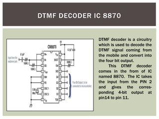
DTMF Controlled
Land Rover
Submitted By
Anurag (452/08)
Shiva Aditya (463/08)
Anshu Agarwal (449/08)
MINOR
PROJECT
With the advancement of Mobile
Communication, It can be used
to control devices. Here we try to
control a simple four wheel robot
with the help of mobile
technology. We use DTMF signals
generated by mobile handset to
control the bot which is located
far away from the base station.
INTRODUCTION
The 12 keys on a cell phone (0,1,8,9,*, #)
has unique signal associated with itself.
This is DTMF signal. When the call is on,
the pressing of any numerical key leads
to generation of DTMF signal which is
audible on the other side. The tone
heard on other side (while call is on) is
DTMF tone. The DTMF tone for each key
is sum of two sinusoidal waves of
frequencies. Thus each key has unique
DTMF TECHNOLOGY
DTMF FREQUENCIES
1209 Hz 1336 Hz 1477 Hz 1633 Hz
697 Hz 1 2 3 A
770 Hz 4 5 6 B
852 Hz 7 8 9 C
941 Hz * 0 # D
Pressing the '1' key will result in a
sound composed of both a 697 and
a 1209 hertz (Hz) tone.
There are two ways to take DTMF output for further use
1. From speaker (that is near to your ear while calling) and
using microphone to convert sound waves to electrical
signals.
2. The other way is through earphone jack. 3.5 MM
EARPHONEJACK. One wire comes from the ground terminal
of the jack that is connected to common ground of the
complete circuit. The other wire can be attached to any one
of two signal terminals.
We use ear phone jack here.
DTMF SIGNAL OUTPUT
DTMF DECODER IC 8870
DTMF decoder is a circuitry
which is used to decode the
DTMF signal coming from
the mobile and convert into
the four bit output.
This DTMF decoder
comes in the from of IC
named 8870. The IC takes
the input from the PIN 2
and gives the corres-
ponding 4-bit output at
pin14 to pin 11.
DECODED FOUR BIT OUTPUT
Transmitting mobile is in
our hand (cell1) and other
on the bot (cell 2). we can
use any mobile as
transmitter. Cell 2 is set to
auto answering mode so
that cell 2 automatically
picks up the call. The
earphone plug, 8870 DTMF
decoder is connected to
cell 2. As we make a call
from cell 1 to cell 2. Cell 2
MOTION TABLE
The respective outputs from the 8870
decoder are fed to the microcontroller
(Port -1) and the controller was
programmed to give corresponding
outputs from port-2. this outputs are
AT89S52 MICROCONTROLLER
• 8 bit CPU with registers
• 16 bit program
counter(PC)
• 8 bit program status
word(PSW)
• 8 bit stack pointer
• Internal ROM of
0(8031) to 4K(8051)
• Internal RAM of 128
Bytes
• 4 register banks 00-1f
We can’t run the motor directly
from the output of microcontroller,
it may damage the ports because of
back EMF generated in the motors.
Therefore, L293D is used to give
power to the drives.
The L293D is quadruple high-
current half-H driver. It designed to
provide bidirectional drive currents
of up to 1 A at voltages from 4.5 V
to 36 V and to drive inductive loads
such as relays, solenoids, dc motors
etc.
L293D
L293D MOTOR INTERFACING
FLOW CHART/ ALGORITHM
mov A,#0FFH
mov p1,A
mov B,#00H
mov p2,B
forward: mov A,p1
cjne A,#0F2H,left //to move forword
setb p2.0
setb p2.2
clr p2.1
clr p2.3
sjmp forward
MICROCONTROLLER PROGRAM
left : cjne A,#0F4H,stop //to move left
setb p2.2
clr p2.0
clr p2.1
clr p2.3
sjmp forward
stop : cjne A,#0F5H,right //to move right
clr p2.0
clr p2.1
clr p2.2
clr p2.3
sjmp forward
right : cjne A,#0F6H,back //to move back
clr p2.1
clr p2.2
clr p2.3
setb p2.0
sjmp forward
back : cjne A,#0F8H,forward //checkagain
setb p2.1
clr p2.0
clr p2.2
setb p2.3
sjmp forward
here:sjmp here
end
BLOCK DIAGRAM
PRACTICAL VALUES
Logic Level
Output
Voltage of
7805
Output Voltage
of CM8870 (V)
Output Voltage
of Microcontroller
TH Exp TH Exp TH Exp
HIGH 5 4.9 4.97 4.62 5 4.45
LOW 0 0.1 0.03 0.01 0 0.2
No. Press Output of
CM8870
Input to MC Output of MC Action
2 0010 0XF2
(11110010)
0xF5
(11110101)
Forward
4 0100 0XF4
(11110100)
0xF4
(11110100)
Left
5 0101 0XF5
(11110101)
0xF0
(11110000)
Stop
6 0110 0XF6
(11110110)
0xF1
(11110001)
Right
8 1000 0XF8
(11111000)
0xFA
(11111010)
Backward
Voltage Values of Different components
Data Output of Different Component
REAL VIEW
1) Scientific
Remote control vehicles have various scientific uses including
hazardous environments, working in the deep ocean, and
space exploration.
2)Military and Law Enforcement
Military usage of remotely controlled military vehicles dates
back to the first half of 20th century. Soviet Red Army used
remotely controlled Teletanks during 1930s in the Winter War
and early stage of World War II.
3)Search and Rescue
UAVs will likely play an increased role in search and rescue
in the United States. This was demonstrated by the
successful use of UAVs during the 2008 hurricanes that struck
Louisiana and Texas.
APPLICATION
1. IR Sensors:
IR sensors can be used to automatically detect & avoid
obstacles if the robot goes beyond line of sight.
2. Password Protection:
Project can be modified in order to password protect the
robot. This introduces conditioned access & increases security
to a great extent.
4. Adding a Camera:
If the current project is interfaced with a camera (e.g. a
Webcam) robot can be driven beyond line-of-sight & range
becomes practically unlimited as GSM networks have a very
large range
FURTHER IMROVEMENTS & FUTURE SCOPE
We hereby express our gratitude towards the ELECTRONICS AND
COMMUNICATION Department of NIT PATNA, to endow us with such an
opportunity for doing this project under the guidance of
Prof. RITESH KUMAR MISHRA.
We also thank our Head of Dept. Mr. RAVINDER KUMAR sir, who was
munificent and humane at the time of requisite. We also would to
mention the name of Prof. B C SAHANA for bestowing us the imperative
knowledge in MICROCONTROLLERS which thoroughly was beneficial in
implementing the project successfully.
CONCLUSION
1. Wikipedia - The free encyclopedia
2. http://www.8051projects.info/
3. http://www.instructables.com/
4. Schenker, L (1960), "Pushbutton Calling with a Two-Group Voice-
Frequency Code", The Bell system technical journal 39 (1): 235 –255,
ISSN 0005-8580
5. “DTMF Tester” , ‘Electronics For You’ Magazine , Edition (June 2003)
6. http://www.alldatasheet.com/
REFERENCES

final ppt2.pptx

  • 1.
    DTMF Controlled Land Rover SubmittedBy Anurag (452/08) Shiva Aditya (463/08) Anshu Agarwal (449/08) MINOR PROJECT
  • 2.
    With the advancementof Mobile Communication, It can be used to control devices. Here we try to control a simple four wheel robot with the help of mobile technology. We use DTMF signals generated by mobile handset to control the bot which is located far away from the base station. INTRODUCTION
  • 3.
    The 12 keyson a cell phone (0,1,8,9,*, #) has unique signal associated with itself. This is DTMF signal. When the call is on, the pressing of any numerical key leads to generation of DTMF signal which is audible on the other side. The tone heard on other side (while call is on) is DTMF tone. The DTMF tone for each key is sum of two sinusoidal waves of frequencies. Thus each key has unique DTMF TECHNOLOGY
  • 4.
    DTMF FREQUENCIES 1209 Hz1336 Hz 1477 Hz 1633 Hz 697 Hz 1 2 3 A 770 Hz 4 5 6 B 852 Hz 7 8 9 C 941 Hz * 0 # D Pressing the '1' key will result in a sound composed of both a 697 and a 1209 hertz (Hz) tone.
  • 5.
    There are twoways to take DTMF output for further use 1. From speaker (that is near to your ear while calling) and using microphone to convert sound waves to electrical signals. 2. The other way is through earphone jack. 3.5 MM EARPHONEJACK. One wire comes from the ground terminal of the jack that is connected to common ground of the complete circuit. The other wire can be attached to any one of two signal terminals. We use ear phone jack here. DTMF SIGNAL OUTPUT
  • 6.
    DTMF DECODER IC8870 DTMF decoder is a circuitry which is used to decode the DTMF signal coming from the mobile and convert into the four bit output. This DTMF decoder comes in the from of IC named 8870. The IC takes the input from the PIN 2 and gives the corres- ponding 4-bit output at pin14 to pin 11.
  • 7.
    DECODED FOUR BITOUTPUT Transmitting mobile is in our hand (cell1) and other on the bot (cell 2). we can use any mobile as transmitter. Cell 2 is set to auto answering mode so that cell 2 automatically picks up the call. The earphone plug, 8870 DTMF decoder is connected to cell 2. As we make a call from cell 1 to cell 2. Cell 2
  • 8.
    MOTION TABLE The respectiveoutputs from the 8870 decoder are fed to the microcontroller (Port -1) and the controller was programmed to give corresponding outputs from port-2. this outputs are
  • 9.
    AT89S52 MICROCONTROLLER • 8bit CPU with registers • 16 bit program counter(PC) • 8 bit program status word(PSW) • 8 bit stack pointer • Internal ROM of 0(8031) to 4K(8051) • Internal RAM of 128 Bytes • 4 register banks 00-1f
  • 10.
    We can’t runthe motor directly from the output of microcontroller, it may damage the ports because of back EMF generated in the motors. Therefore, L293D is used to give power to the drives. The L293D is quadruple high- current half-H driver. It designed to provide bidirectional drive currents of up to 1 A at voltages from 4.5 V to 36 V and to drive inductive loads such as relays, solenoids, dc motors etc. L293D
  • 11.
  • 12.
  • 13.
    mov A,#0FFH mov p1,A movB,#00H mov p2,B forward: mov A,p1 cjne A,#0F2H,left //to move forword setb p2.0 setb p2.2 clr p2.1 clr p2.3 sjmp forward MICROCONTROLLER PROGRAM
  • 14.
    left : cjneA,#0F4H,stop //to move left setb p2.2 clr p2.0 clr p2.1 clr p2.3 sjmp forward stop : cjne A,#0F5H,right //to move right clr p2.0 clr p2.1 clr p2.2 clr p2.3 sjmp forward right : cjne A,#0F6H,back //to move back clr p2.1 clr p2.2 clr p2.3 setb p2.0 sjmp forward back : cjne A,#0F8H,forward //checkagain setb p2.1 clr p2.0 clr p2.2 setb p2.3 sjmp forward here:sjmp here end
  • 15.
  • 16.
    PRACTICAL VALUES Logic Level Output Voltageof 7805 Output Voltage of CM8870 (V) Output Voltage of Microcontroller TH Exp TH Exp TH Exp HIGH 5 4.9 4.97 4.62 5 4.45 LOW 0 0.1 0.03 0.01 0 0.2 No. Press Output of CM8870 Input to MC Output of MC Action 2 0010 0XF2 (11110010) 0xF5 (11110101) Forward 4 0100 0XF4 (11110100) 0xF4 (11110100) Left 5 0101 0XF5 (11110101) 0xF0 (11110000) Stop 6 0110 0XF6 (11110110) 0xF1 (11110001) Right 8 1000 0XF8 (11111000) 0xFA (11111010) Backward Voltage Values of Different components Data Output of Different Component
  • 17.
  • 18.
    1) Scientific Remote controlvehicles have various scientific uses including hazardous environments, working in the deep ocean, and space exploration. 2)Military and Law Enforcement Military usage of remotely controlled military vehicles dates back to the first half of 20th century. Soviet Red Army used remotely controlled Teletanks during 1930s in the Winter War and early stage of World War II. 3)Search and Rescue UAVs will likely play an increased role in search and rescue in the United States. This was demonstrated by the successful use of UAVs during the 2008 hurricanes that struck Louisiana and Texas. APPLICATION
  • 19.
    1. IR Sensors: IRsensors can be used to automatically detect & avoid obstacles if the robot goes beyond line of sight. 2. Password Protection: Project can be modified in order to password protect the robot. This introduces conditioned access & increases security to a great extent. 4. Adding a Camera: If the current project is interfaced with a camera (e.g. a Webcam) robot can be driven beyond line-of-sight & range becomes practically unlimited as GSM networks have a very large range FURTHER IMROVEMENTS & FUTURE SCOPE
  • 20.
    We hereby expressour gratitude towards the ELECTRONICS AND COMMUNICATION Department of NIT PATNA, to endow us with such an opportunity for doing this project under the guidance of Prof. RITESH KUMAR MISHRA. We also thank our Head of Dept. Mr. RAVINDER KUMAR sir, who was munificent and humane at the time of requisite. We also would to mention the name of Prof. B C SAHANA for bestowing us the imperative knowledge in MICROCONTROLLERS which thoroughly was beneficial in implementing the project successfully. CONCLUSION
  • 21.
    1. Wikipedia -The free encyclopedia 2. http://www.8051projects.info/ 3. http://www.instructables.com/ 4. Schenker, L (1960), "Pushbutton Calling with a Two-Group Voice- Frequency Code", The Bell system technical journal 39 (1): 235 –255, ISSN 0005-8580 5. “DTMF Tester” , ‘Electronics For You’ Magazine , Edition (June 2003) 6. http://www.alldatasheet.com/ REFERENCES