This document provides an overview of fundamental electrical concepts, including:
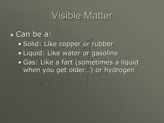
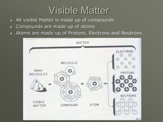
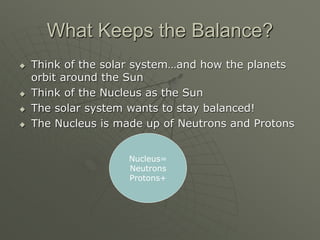
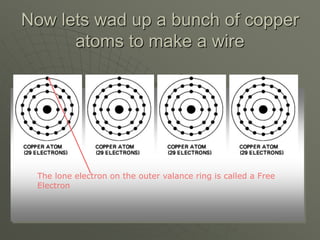
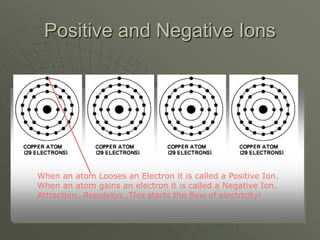
- The structure of atoms and how they form compounds and matter.
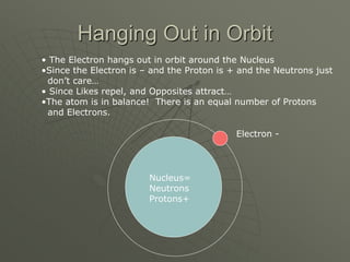
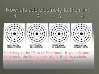
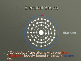
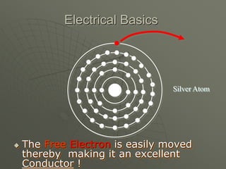
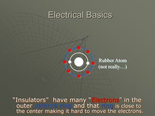
- How electrons orbit the nucleus in atoms and the roles of protons, neutrons, and electrons.
- The two main types of electrical current used in vehicles.
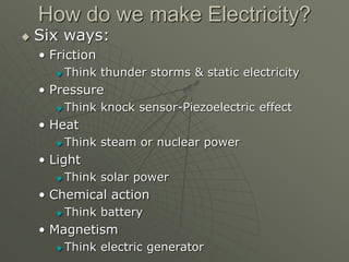
- The six main ways electricity is generated, including chemical action, magnetism, and pressure.
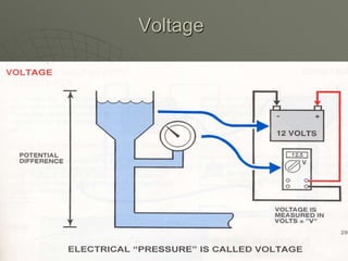
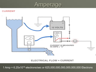
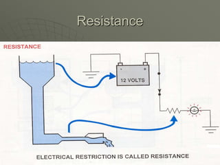
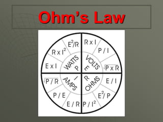
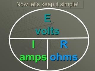
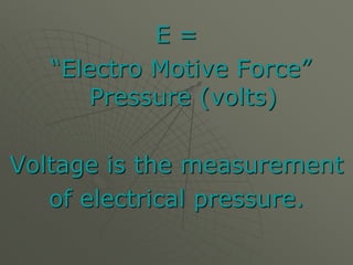
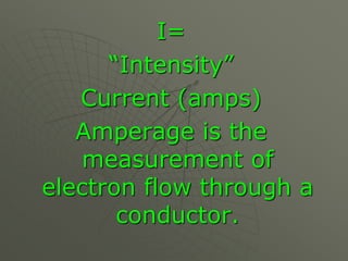
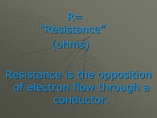
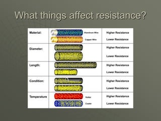
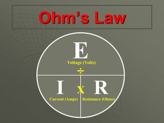
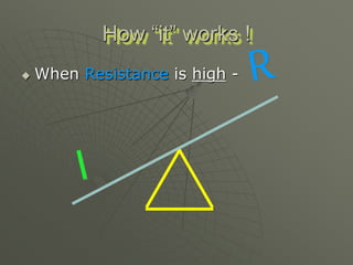
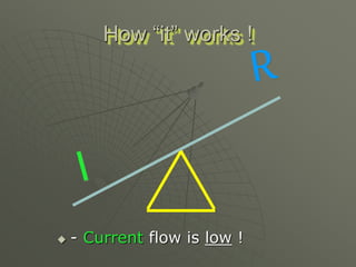
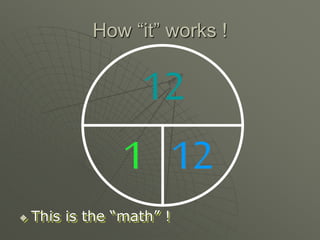
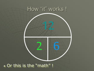
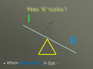
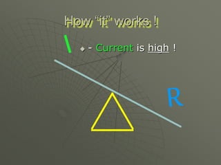
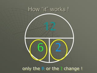
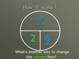
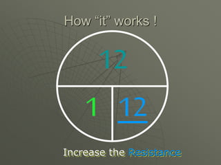
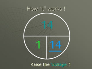
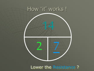
- Key electrical terms like voltage, current, resistance, and Ohm's Law.
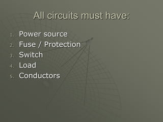
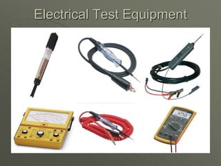
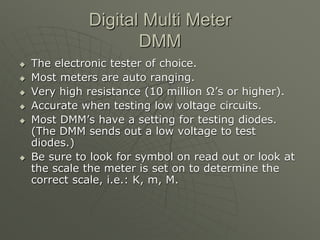
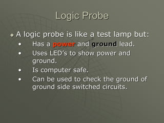
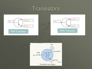
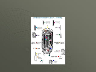
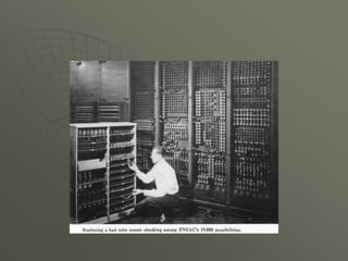
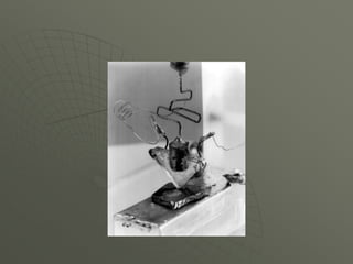
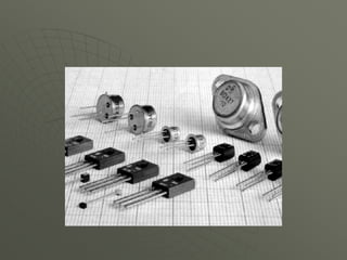
- Common electrical components like transistors, diodes, and test equipment.


![Electronic fuel injection system [EFI]](https://cdn.slidesharecdn.com/ss_thumbnails/efibilkulfinal-171227111232-thumbnail.jpg?width=640&height=640&fit=bounds)