The document discusses electrical principles including:
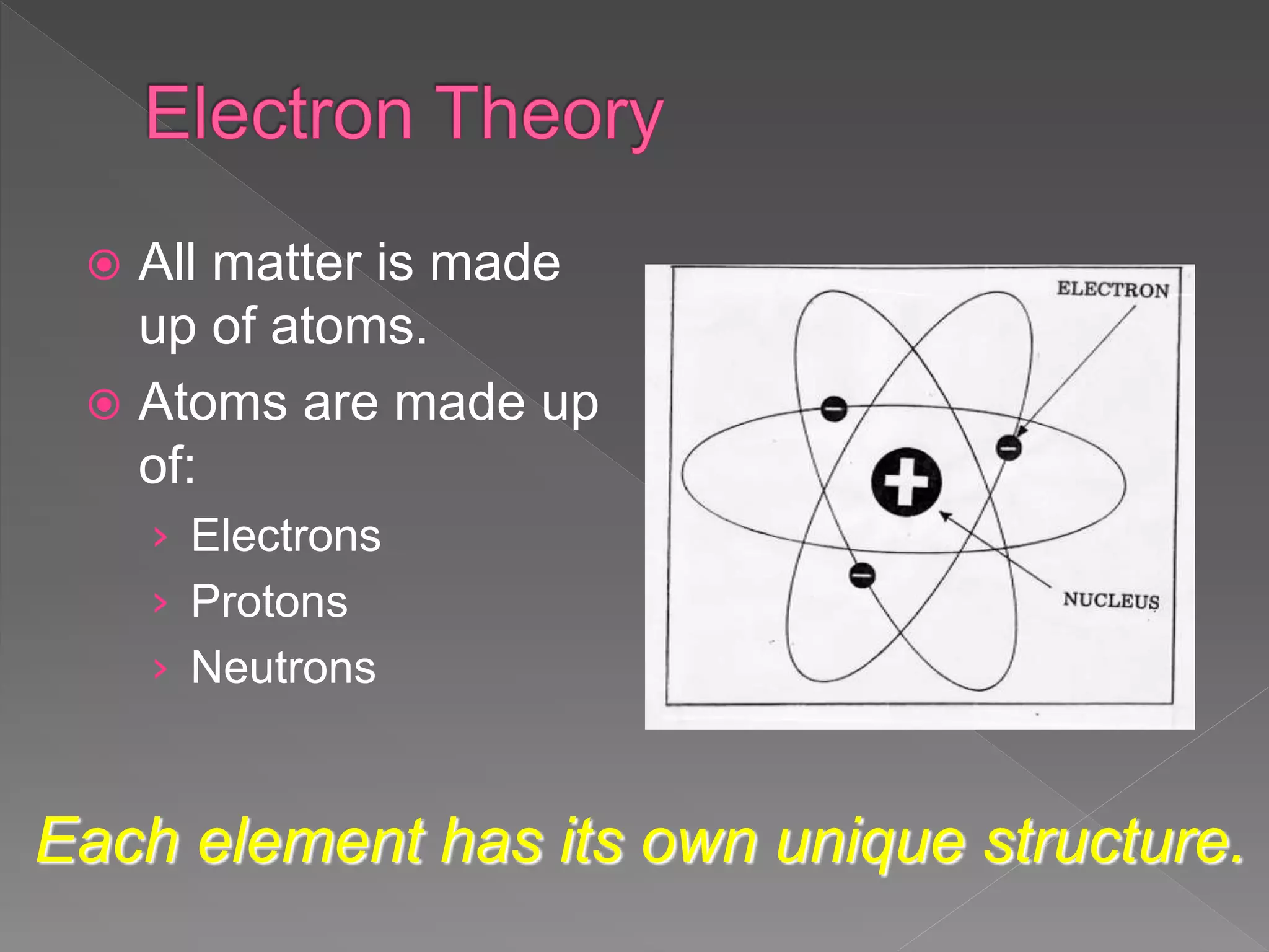
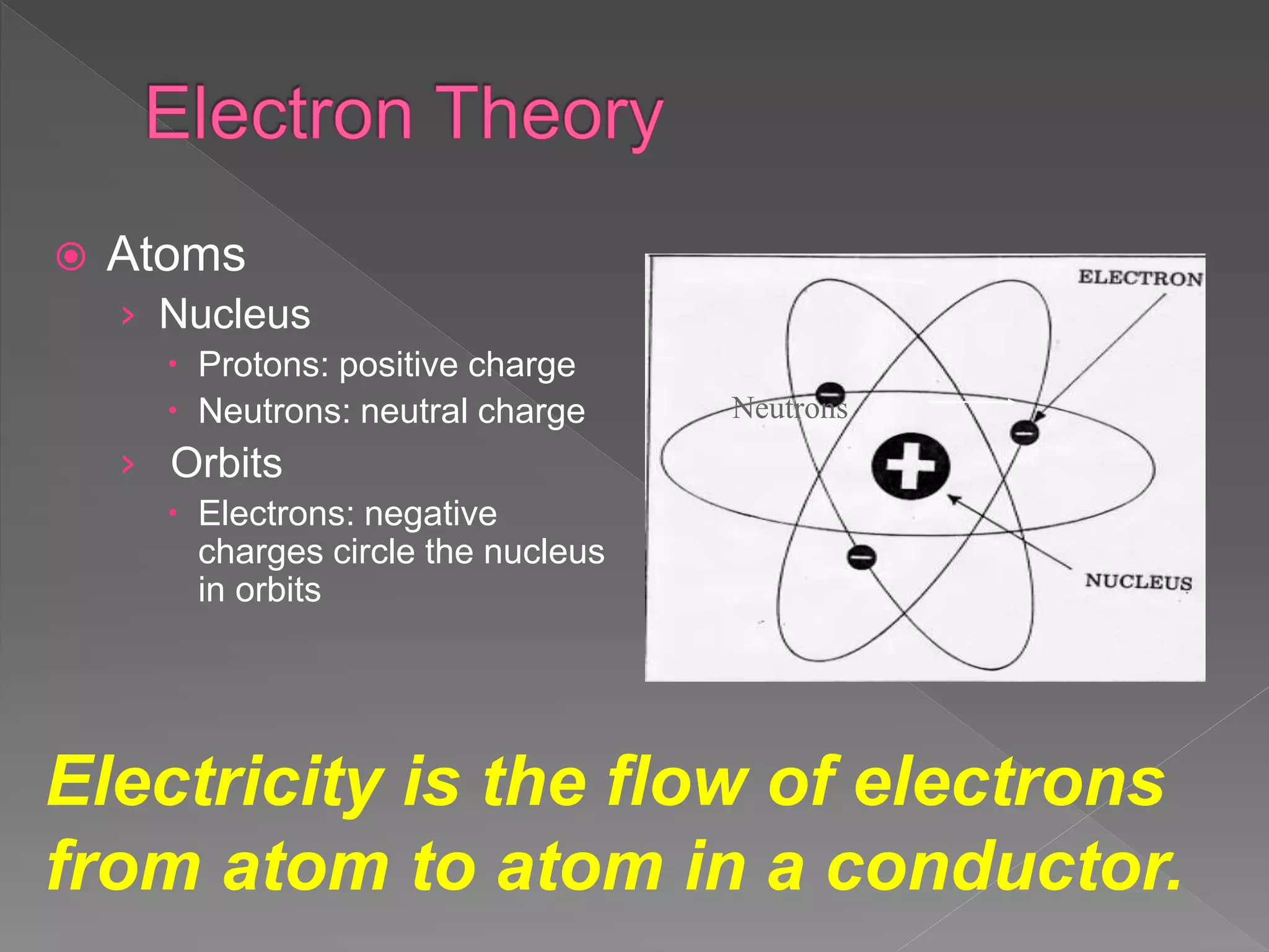
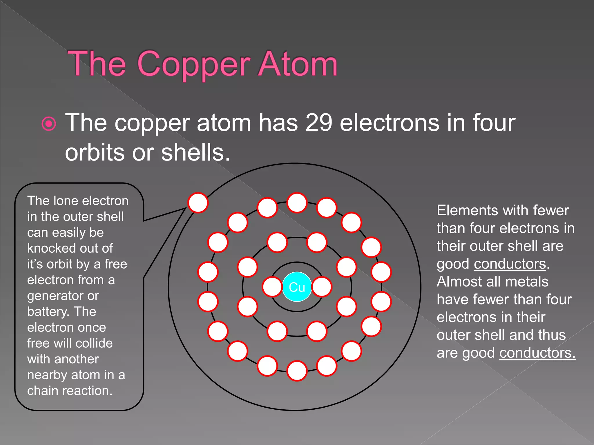
- Electricity is the flow of electrons from atom to atom in a conductor.
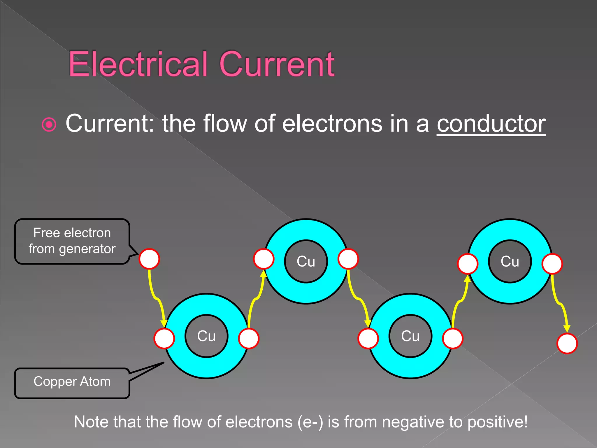
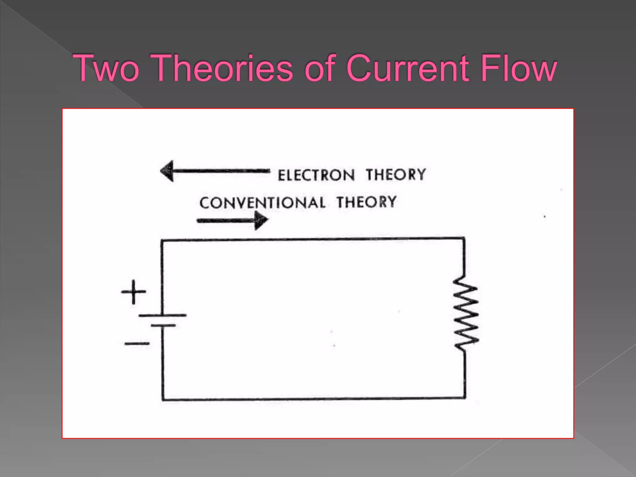
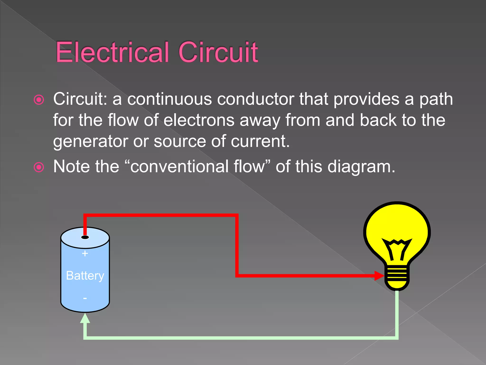
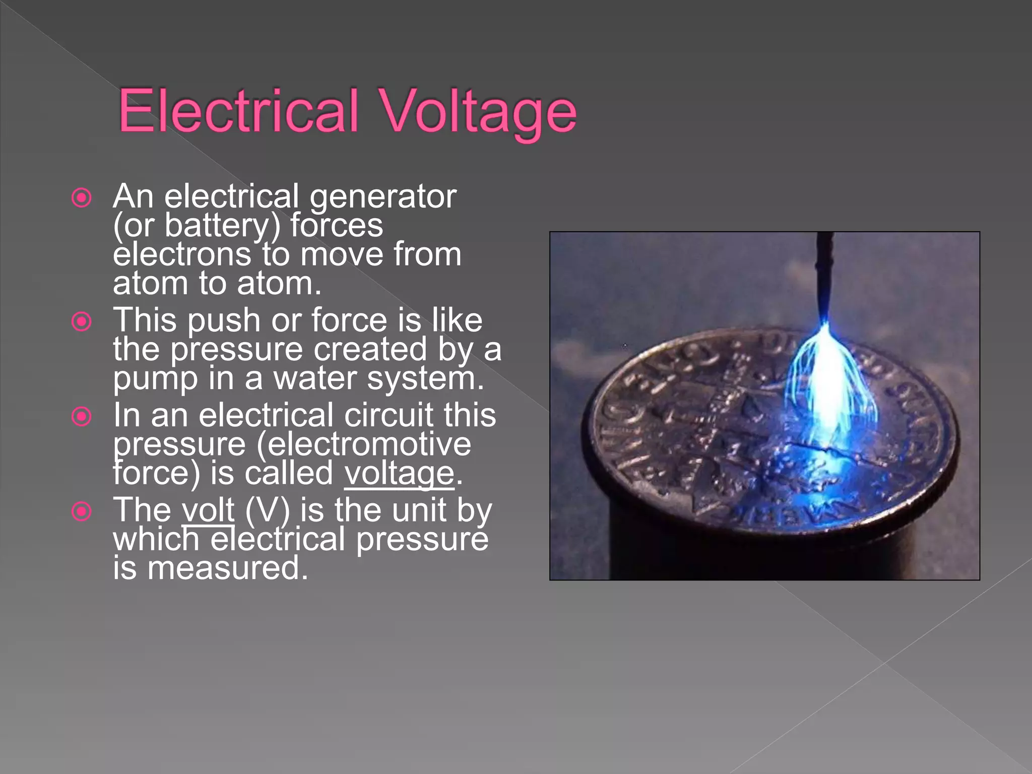
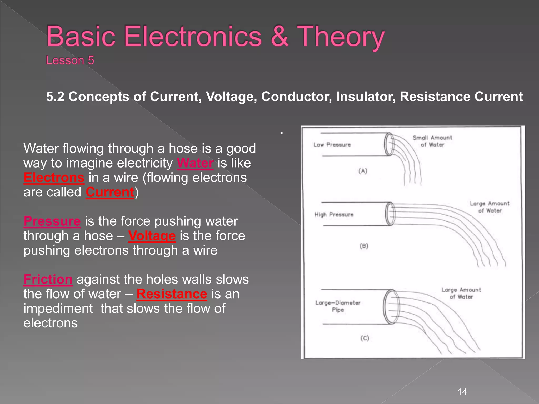
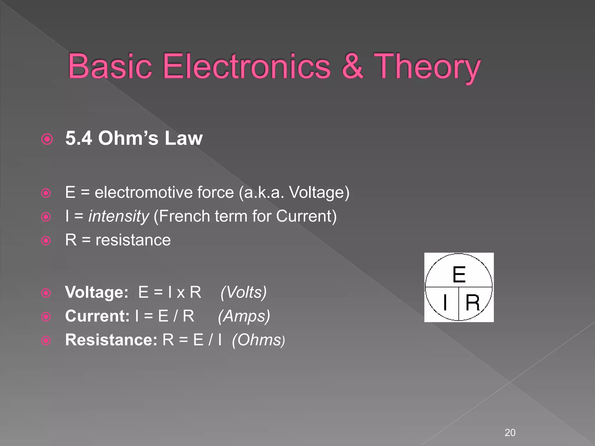
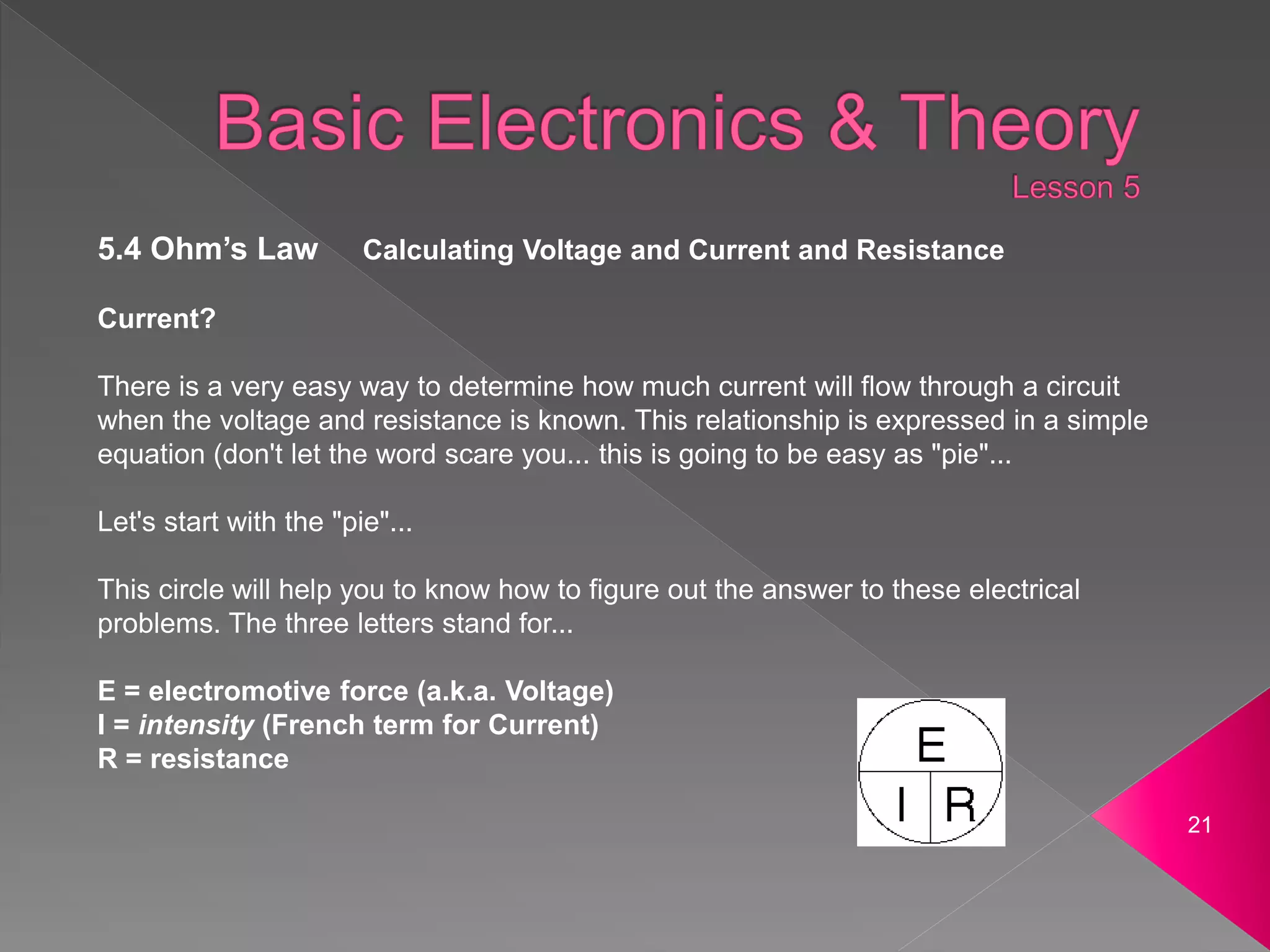
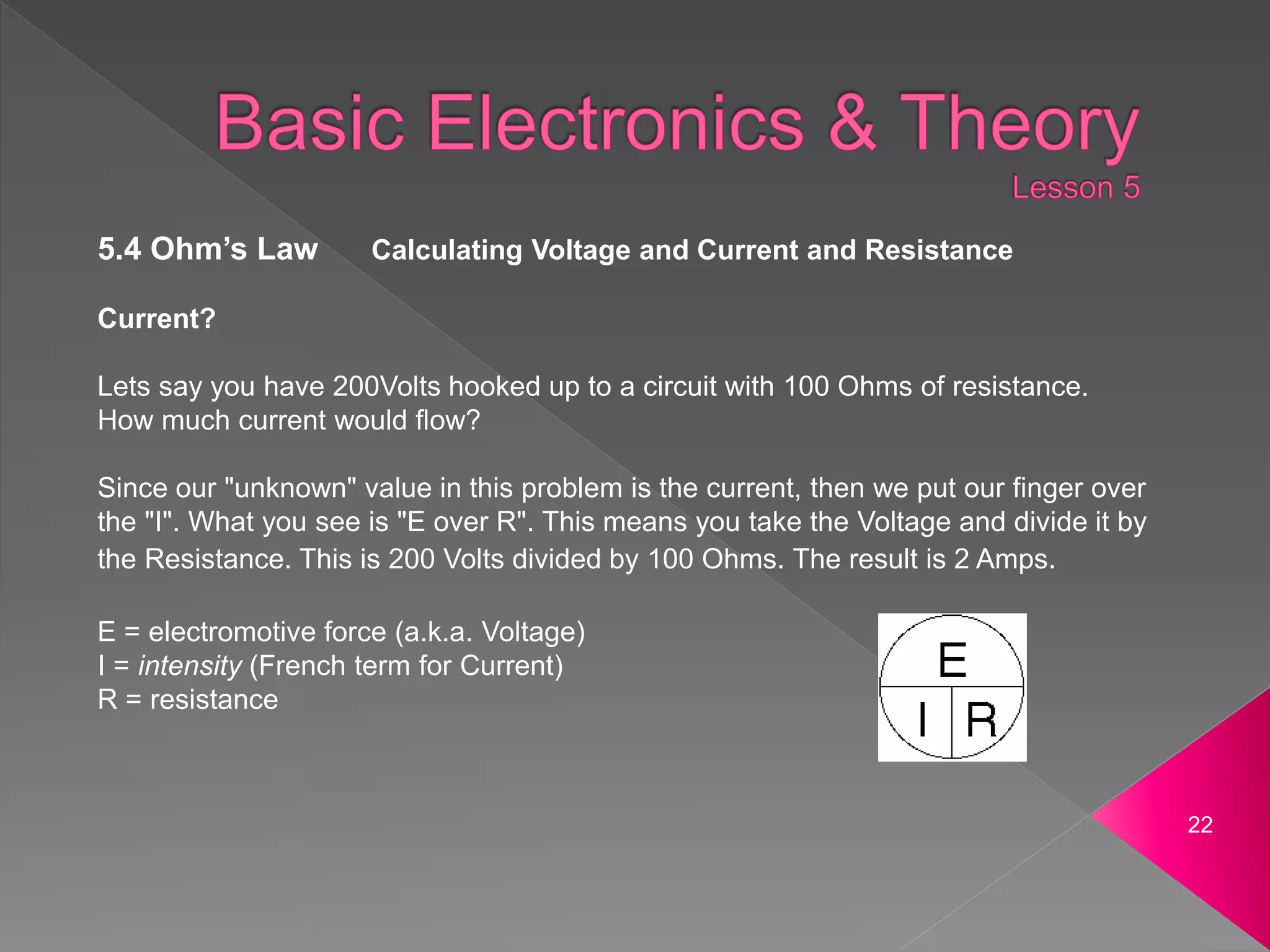
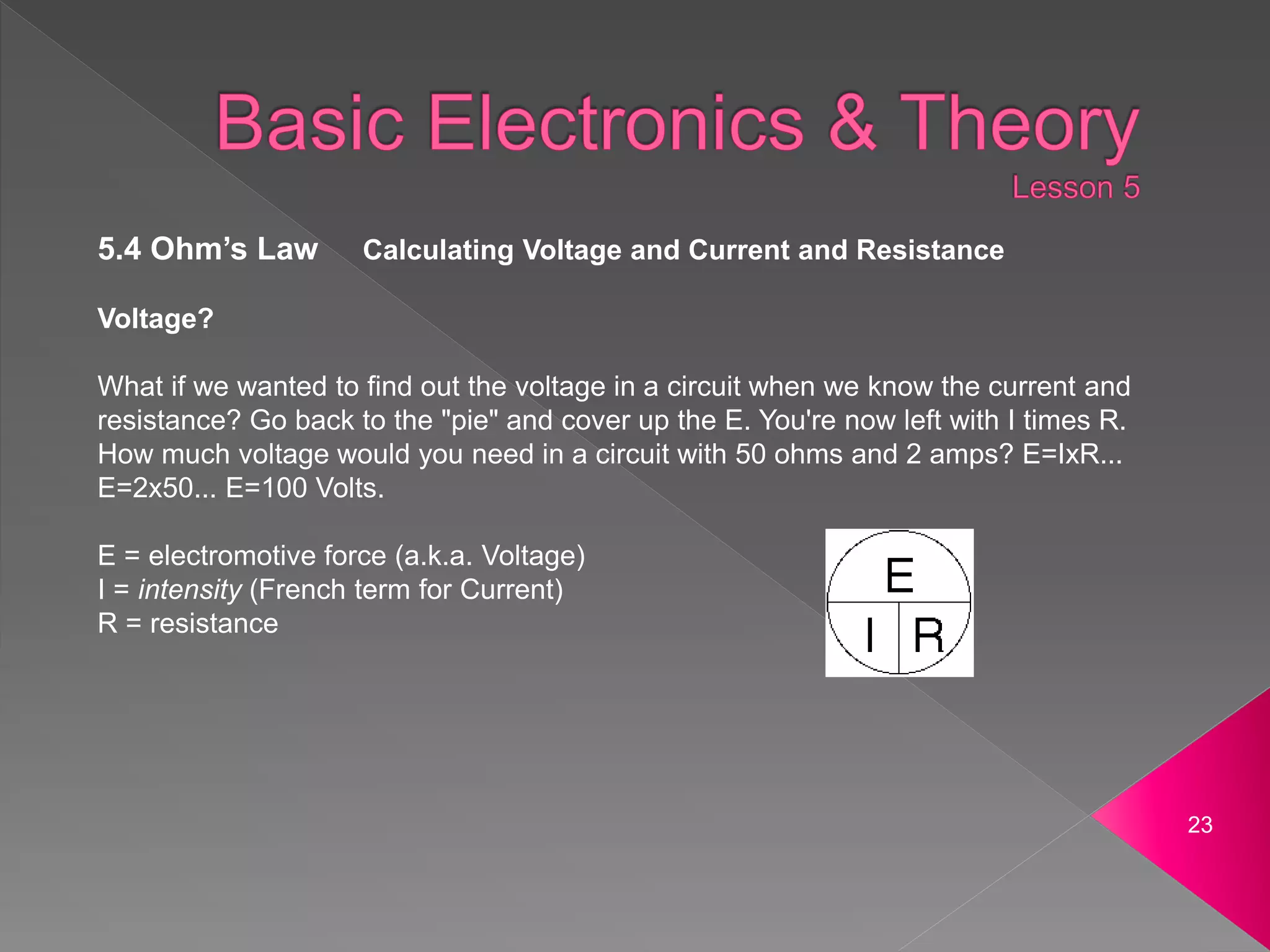
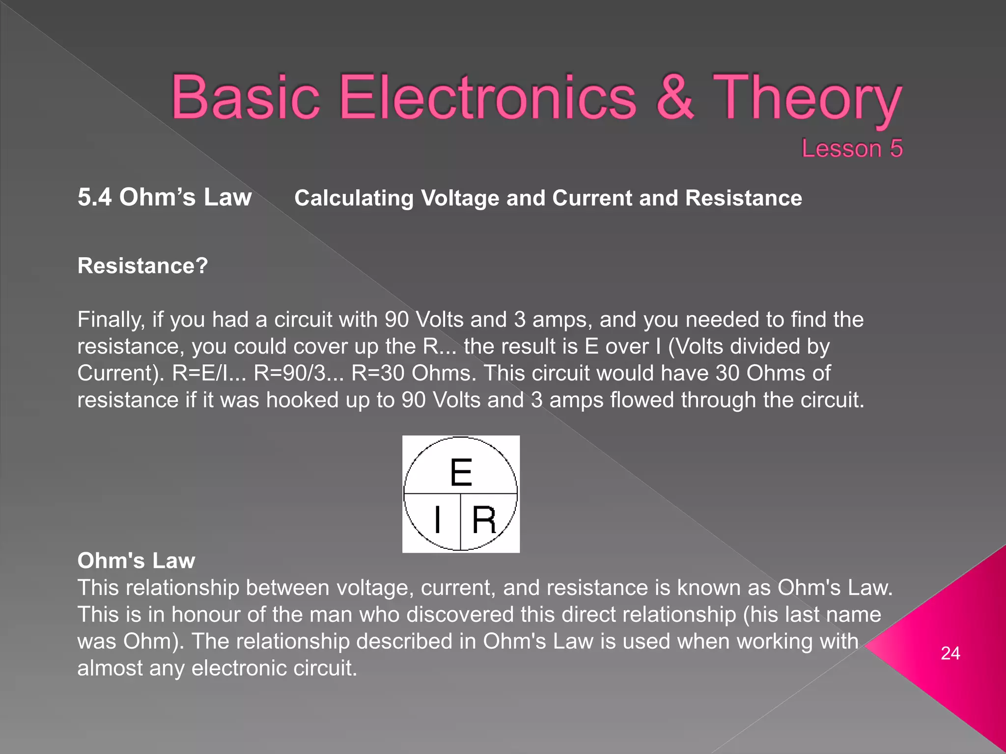
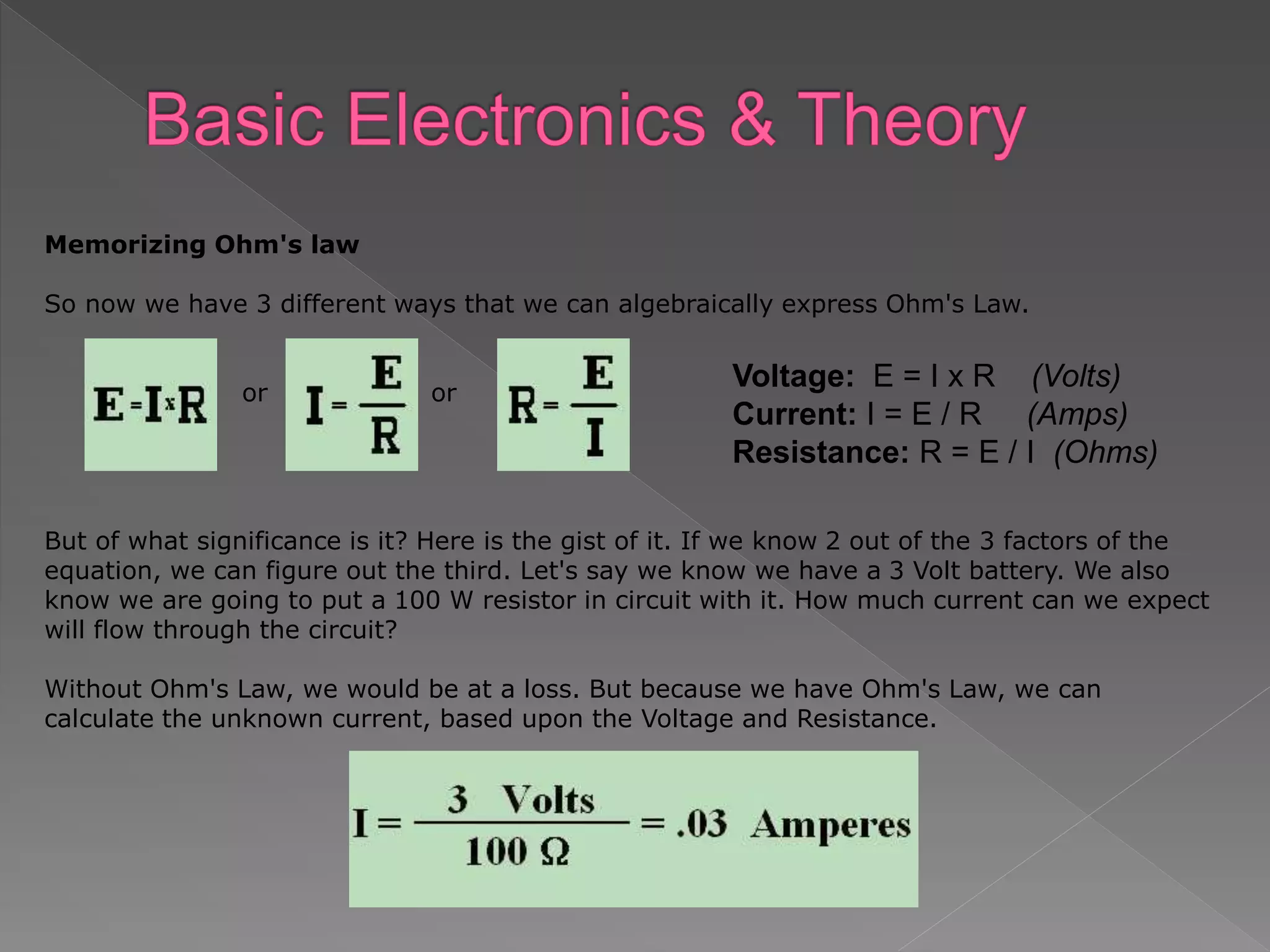
- Current, voltage, resistance, and Ohm's Law are defined. Current is the flow of electrons, voltage is electrical pressure, and resistance opposes current flow.
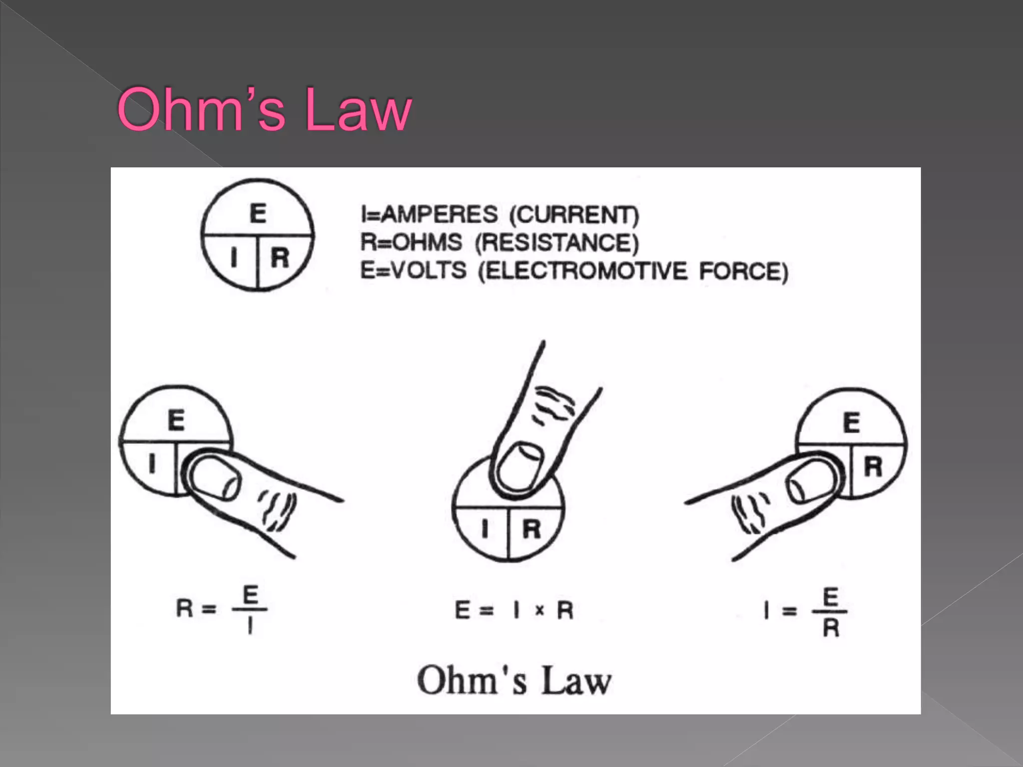
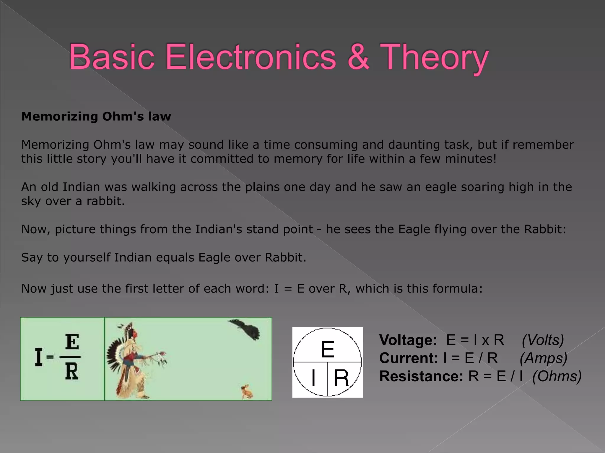
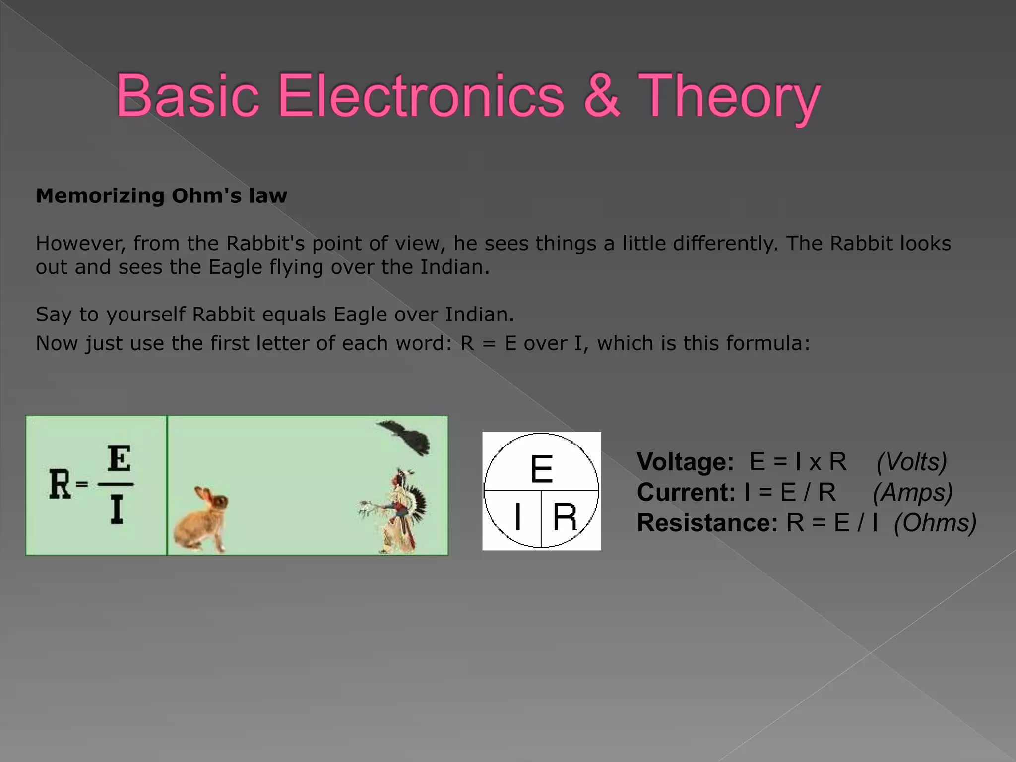
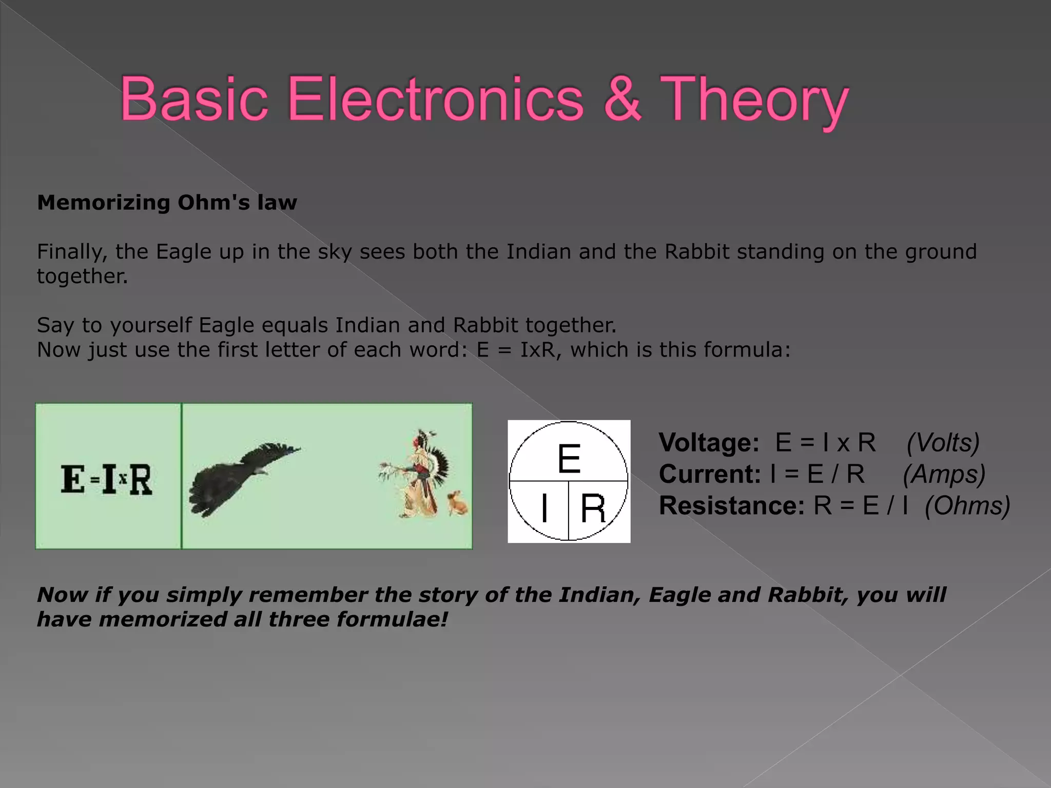
- Ohm's Law states the mathematical relationship between current, voltage, and resistance in a circuit.
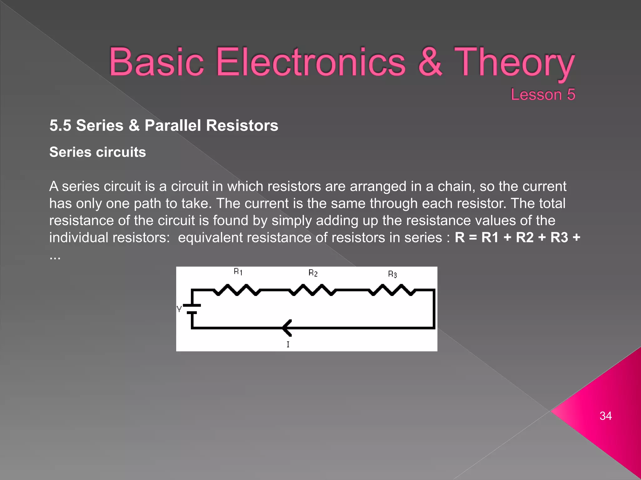
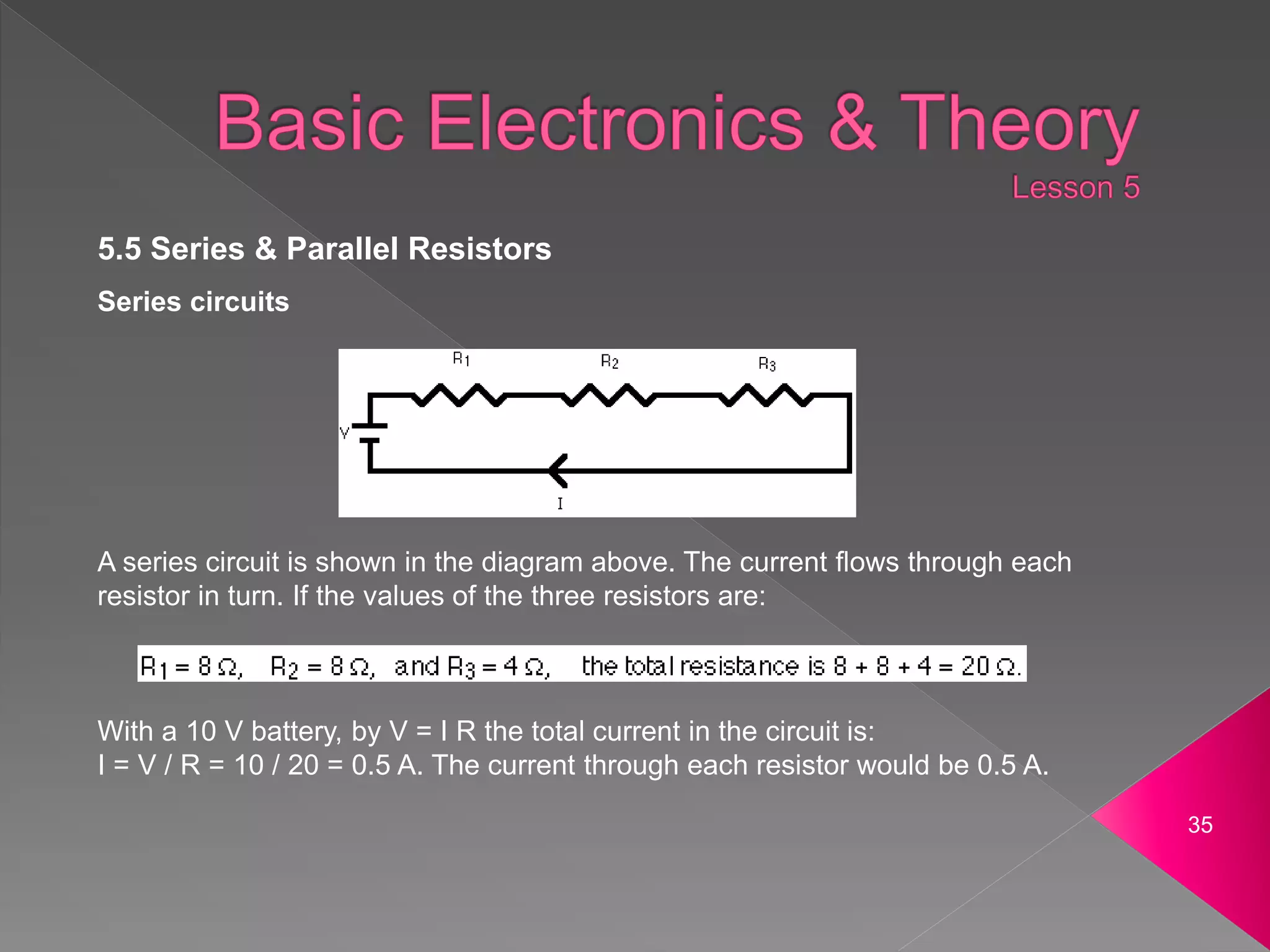
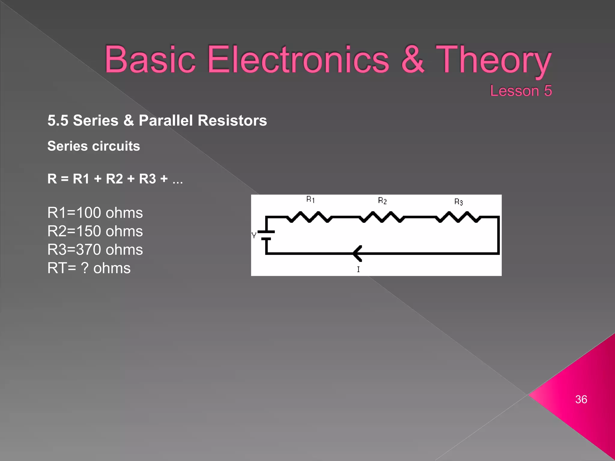
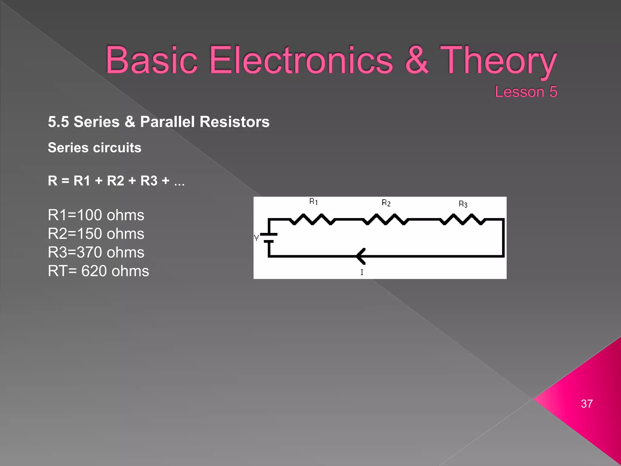
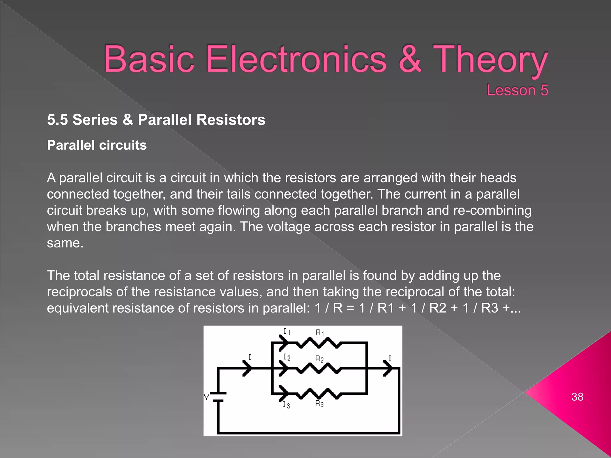
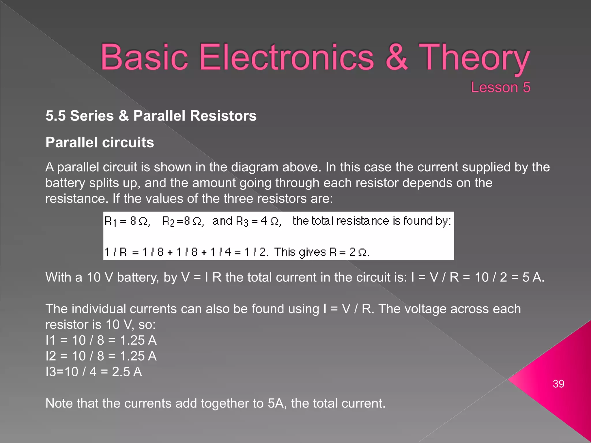
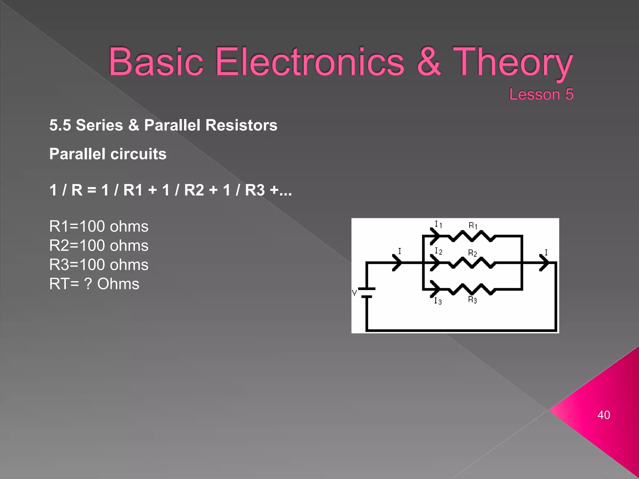
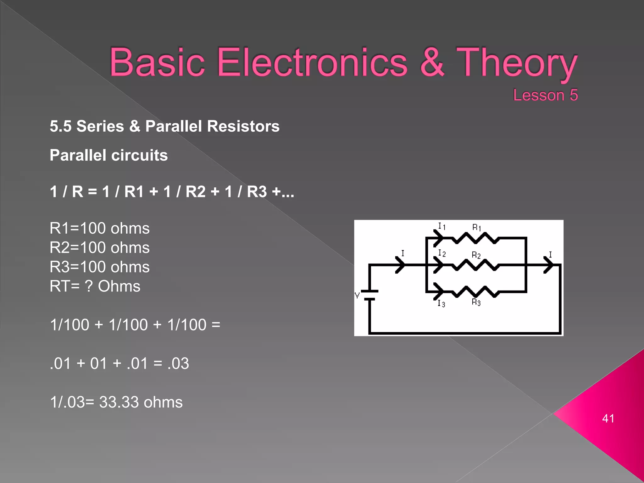
- Circuits can be connected in series or parallel. In series the current is the same in each part and the total resistance is the sum of individual resistances. In parallel the voltage is the same across each part and the total resistance is lower than the lowest individual resistance.
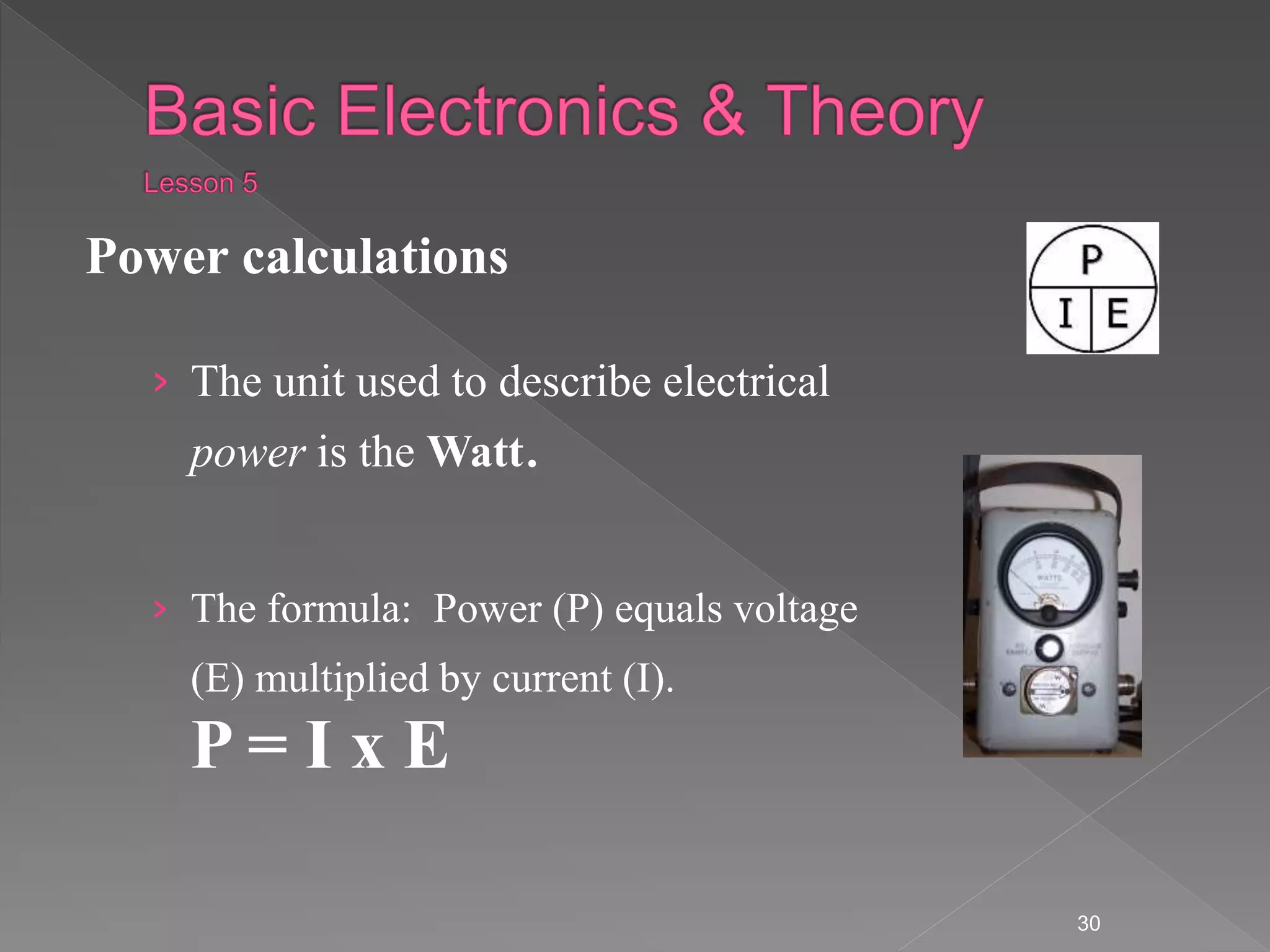
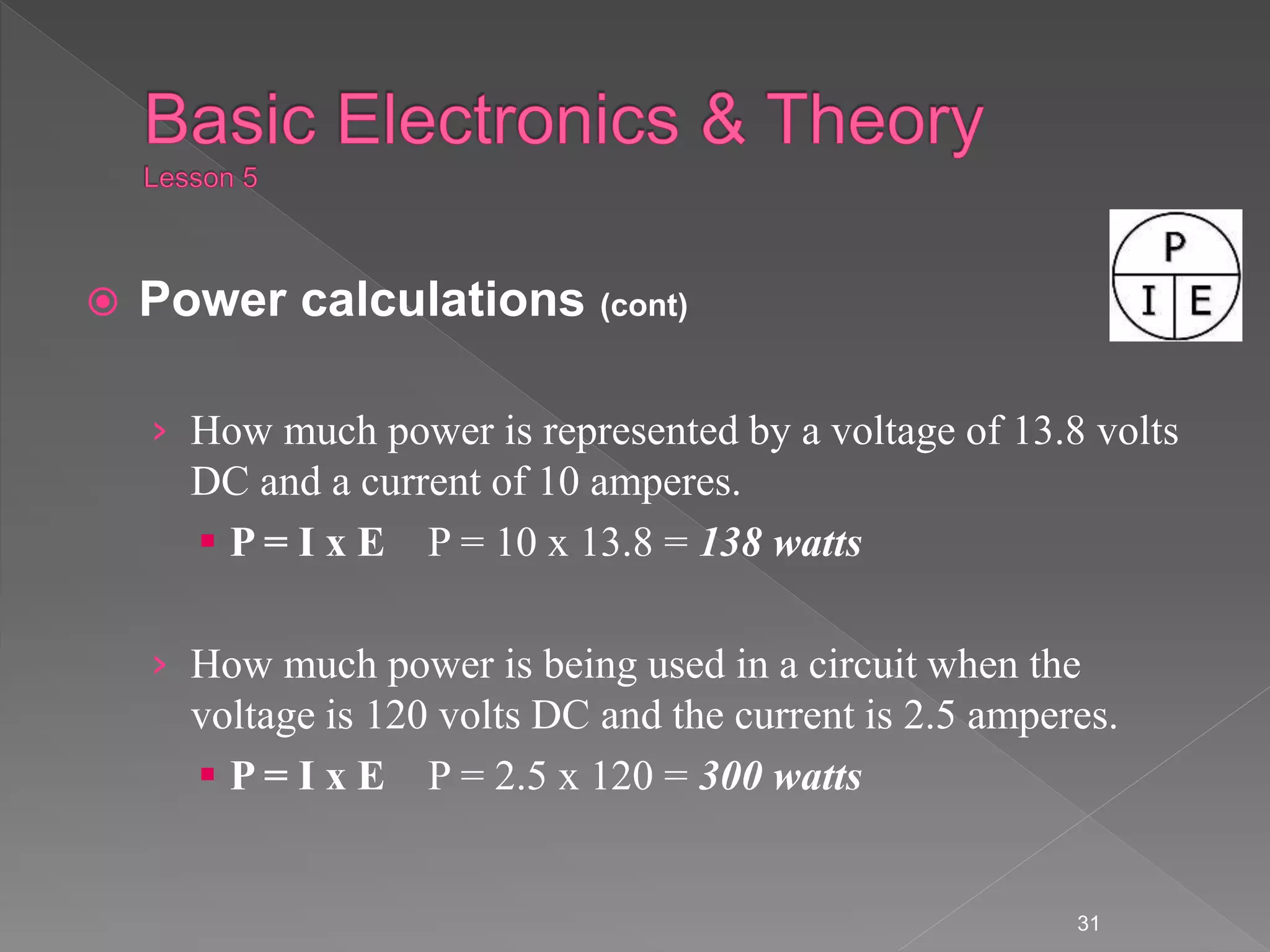
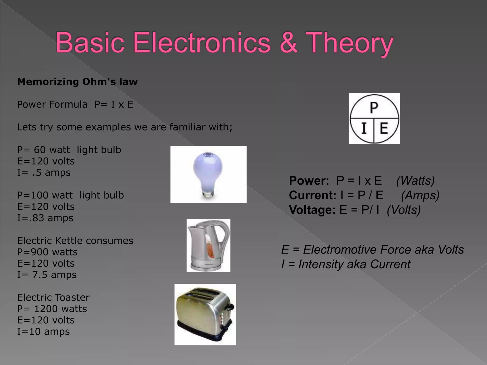
![ Power calculations (cont)
› You can you determine how many watts are being drawn
[consumed] by your transceiver when you are transmitting
by measuring the DC voltage at the transceiver and
multiplying by the current drawn when you transmit.
› How many amperes is flowing in a circuit when the
applied voltage is 120 volts DC and the load is 1200 watts.
I = P/E I = 1200/120 = 10 amperes.
32](https://image.slidesharecdn.com/basicelectricaltheory-221012043009-ce8f70b4/75/Basic-Electrical-Theory-ppt-32-2048.jpg)