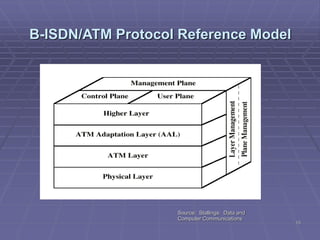
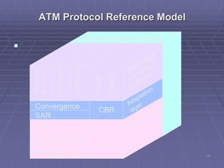
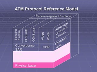
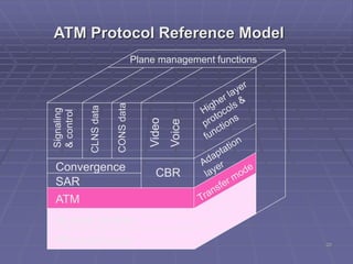
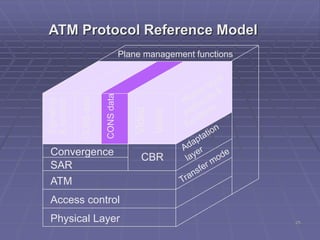
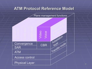
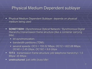
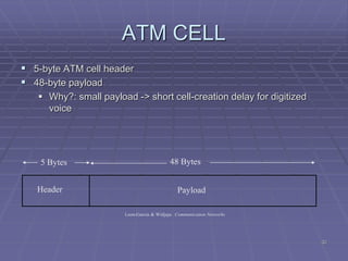
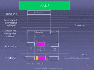
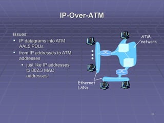
www.oeclib.in
Submitted By:
Odisha Electronics Control Library
Seminar
On
ATM
2
OUTLINE
Introduction to ATM
Principal Characteristics of ATM
Why ATM?
ATM Networks and Interfaces
How Does ATM Work?
ATM Protocol Architecture
Physical Layer
ATM Layer
ATM Adaptation Layer (AAL)
IP OVER ATM
3
WHAT’S ATM?
 ATM is Asynchronous Transfer Mode.
 ATM is a connection-oriented, high-speed, low-
delay switching and transmission technology
that uses short and fixed-size packets, called
cells, to transport information.
 ATM is originally the transfer mode for
implementing Broadband ISDN (B-ISDN) but it is
also implemented in non-ISDN environments where
very high data rates are required
4
BROADBAND AND B-ISDN
 Broadband:
"A service or system requiring transmission channel capable of
supporting rates greater than the primary rate.“
 Broadband-Integrated Service Digital Network (B-ISDN):
A standard for transmitting voice, video and data at the same time
over fiber optic telephone lines
The goal of B-ISDN is to accommodate all existing services along
with those that will come in the future. The services that
BISDN will support include
(1) narrowband services, such as voice, voiceband data, facsimile,
telemetry, videotex, electronic mail,
(2) wideband services such as T1, and
(3) broadband services such as video conference, high speed data,
video on demand. BISDN is also to support point-to-point, point-
to-multipoint and multipoint-to-multipoint connectivities.
5
ATM OVERVIEW
 Used in both WAN and LAN settings
 Signaling (connection setup) Protocol:
 Packets are called cells (53 bytes)
 5-byte header + 48-byte payload
 Commonly transmitted over SONET
 other physical layers possible
 Connections can be switched (SVC), or permanent (PVC).
 ATM operates on a best effort basis.
 ATM guarantees that cells will not be disordered.
 Two types of connections:
 Point-to-point
 Multipoint (Multicast)
 Four Types of Services:
 CBR (Constant Bit Rate)
 VBR (Variable Bit Rate)
 ABR (Available Bit Rate) Flow Control, Rate-based, Credit-
based
 UBR (Unspecific Bit Rate) No Flow control.
6
ATM Characteristics
 No error protection or flow control on a link-by-link basis.
 ATM operates in a connection-oriented mode.
 The header functionality is reduced.
 The information field length is relatively small and fixed.
 All data types are the same
7
Why ATM?
 International standard-based technology (for
interoperability)
 Low network latency (for voice, video, and real-time
applications)
 Low variance of delay (for voice and video transmission)
 Guaranteed quality of service
 High capacity switching (multi-giga bits per second)
 Bandwidth flexibility (dynamically assigned to users)
8
Why ATM? (con’t)
 Scalability (capacity may be increased on demand)
 Medium not shared for ATM LAN (no degradation in performance as
traffic load or number of users increases)
 Supports a wide range of user access speeds
 Appropriate (seamless integration) for LANs, MANs, and WANs
 Supports audio, video, imagery, and data traffic (for integrated
services)
9
ATM NETWORKS
 Public ATM Network:
 Provided by public telecommunications carriers (e.g.,
AT&T, MCI WorldCom, and Sprint)
 Interconnects private ATM networks
 Interconnects remote non-ATM LANs
 Interconnects individual users
 Private ATM Network:
 Owned by private organizations
 Interconnects low speed/shared medium LANs (e.g.,
Ethernet, Token Ring, FDDI) as a backbone network
 Interconnects individual users as the front-end LAN for high
performance or multimedia applications
10
Switches in
the middle
End systems
of ATM
11
Public
ATM Network
Token
Ring
Token
Ring
FDDI
FDDI
Mainframe
Computer
Video
Video
Video
Ethernet
Ethernet
Mainframe
Computer
Edge
Switch
Ethernet
File
Server
Private
ATM
Switch
Edge
Switch
Edge
Switch
Edge
Switch
PBX
PBX
Voice
Voice
Private
ATM
Network
FDDI
12
ATM Interfaces

Private
UNI
Private
ATM LAN
Public
UNI
Public
ATM Network
Public
ATM Network
B-ICI
Private
ATM WAN
P-NNI
13
How ATM Works?
 ATM is connection-oriented -- an end-to-end connection must be
established and routing tables setup prior to cell transmission
 Once a connection is established, the ATM network will provide end-
to-end Quality of Service (QoS) to the end users
 All traffic, whether voice, video, image, or data is divided into 53-
byte cells and routed in sequence across the ATM network
 Routing information is carried in the header of each cell
 Routing decisions and switching are performed by hardware in ATM
switches
 Cells are reassembled into voice, video, image, or data at the
destination
14
ATM Network
H
H
H H H
H
H
H
Voice Video Data
Voice Video Data
BISDN
Services
BISDN
Services
Reassembly
User Applications User Applications
Workstation Workstation
Multiplexing Demultiplexing
H H H H
H H
Segmentation
15
B-ISDN/ATM Protocol Reference Model
Source: Stallings: Data and
Computer Communications
16
ATM Protocol Reference Model

Convergence
SAR
ATM
Access control
Physical Layer
CBR
Signaling
&control
CLNSdata
CONSdata
Video
Voice
Plane management functions
17
ATM Protocol Reference Model
Convergence
SAR
ATM
Access control
Physical Layer
CBR
Signaling
&control
CLNSdata
CONSdata
Video
Voice
Plane management functions
18
ATM Protocol Reference Model
Convergence
SAR
ATM
Access control
Physical Layer
CBR
Signaling
&control
CLNSdata
CONSdata
Video
Voice
Plane management functions
19
ATM Protocol Reference Model
Convergence
SAR
ATM
Access control
Physical Layer
CBR
Signaling
&control
CLNSdata
CONSdata
Video
Voice
Plane management functions
20
ATM Protocol Reference Model
Convergence
SAR
ATM
Access control
Physical Layer
CBR
Signaling
&control
CLNSdata
CONSdata
Video
Voice
Plane management functions
21
ATM Protocol Reference Model
Convergence
SAR
ATM
Access control
Physical Layer
CBR
Signaling
&control
CLNSdata
CONSdata
Video
Voice
Plane management functions
22
ATM Protocol Reference Model
Convergence
SAR
ATM
Access control
Physical Layer
CBR
Signaling
&control
CLNSdata
CONSdata
Video
Voice
Plane management functions
23
ATM Protocol Reference Model
Convergence
SAR
ATM
Access control
Physical Layer
CBR
Signaling
&control
CLNSdata
CONSdata
Video
Voice
Plane management functions
24
ATM Protocol Reference Model
Convergence
SAR
ATM
Access control
Physical Layer
CBR
Signaling
&control
CLNSdata
CONSdata
Video
Voice
Plane management functions
25
ATM Protocol Reference Model
Convergence
SAR
ATM
Access control
Physical Layer
CBR
Signaling
&control
CLNSdata
CONSdata
Video
Voice
Plane management functions
26
ATM Protocol Reference Model
Convergence
SAR
ATM
Access control
Physical Layer
CBR
Signaling
&control
CLNSdata
CONSdata
Video
Voice
Plane management functions
27
ATM Protocol Reference Model
Convergence
SAR
ATM
Access control
Physical Layer
CBR
Signaling
&control
CLNSdata
CONSdata
Video
Voice
Plane management functions
28
ATM Physical Layer
29
TCS
 Transmission Convergence Sublayer (TCS): adapts ATM layer above to
PMD sublayer below
 Header checksum generation: 8 bits CRC
 Cell delineation
 With “unstructured” PMD sublayer, transmission of idle cells
when no data cells to send
30
Physical Medium Dependent sublayer
 Physical Medium Dependent Sublayer: depends on physical
medium being used
 SONET/SDH: (Synchronous Optical Network / Synchronous Digital
Hierarchy) transmission frame structure (like a container carrying
bits);
 bit synchronization;
 bandwidth partitions (TDM);
 several speeds: OC3 = 155.52 Mbps; OC12 = 622.08 Mbps;
OC48 = 2.45 Gbps, OC192 = 9.6 Gbps
 TI/T3: transmission frame structure (old telephone hierarchy): 1.5
Mbps/ 45 Mbps
 unstructured: just cells (busy/idle)
31
ATM LAYER
 The ATM layer provides for the transparent transport of fixed sized
ATM layer service data units between communicating upper layer
entities (e.g., ATM Adaptation Layer).
 An interface between the AAL and the physical layer
32
ATM CELL
 5-byte ATM cell header
 48-byte payload
 Why?: small payload -> short cell-creation delay for digitized
voice
Header Payload
5 Bytes 48 Bytes
Leon-Garcia & Widjaja: Communication Networks
33
ATM CELL HEADER FORMAT (UNI)
GFC: Generic Flow Control
VPI: Virtual Path Identifier
VCI: Virtual Circuit Identifier
PTI: Payload Type Indicator
CLP: Cell Loss Priority
HEC: Header Error Control
34
ATM CELL HEADER FORMAT (NNI)
VPI: Virtual Path Identifier
VCI: Virtual Circuit Identifier
PTI: Payload Type Indicator
CLP: Cell Loss Priority
HEC: Header Error Control
35
ATM SERVICES
Service: transport cells across ATM network
analogous to IP network layer
very different services than IP network layer
Network
Architecture
Internet
ATM
ATM
ATM
ATM
Service
Model
best effort
CBR
VBR
ABR
UBR
Bandwidth
none
constant
rate
guaranteed
rate
guaranteed
minimum
none
Loss
no
yes
yes
no
no
Order
no
yes
yes
yes
yes
Timing
no
yes
yes
no
no
Congestion
feedback
no (inferred
via loss)
no
congestion
no
congestion
yes
no
Guarantees ?
36
ATM VIRTUAL CIRCUITS
 VC transport: cells carried on VC from source to destination
 call setup, teardown for each call before data can flow
 each packet carries VC identifier (not destination ID)
 every switch on source-dest path maintain “state” for each
passing connection
 link,switch resources (bandwidth, buffers) may be allocated to
VC: to get circuit-like perf.
 Permanent VCs (PVCs)
 long lasting connections
 typically: “permanent” route between to IP routers
 Switched VCs (SVC):
 dynamically set up on per-call basis
37
Virtual Channels
 The virtual channel (VC) is the fundamental unit of
transport in a B-ISDN. Each ATM cell contains an explicit
label in its header to identify the virtual channel.
 a Virtual Channel Identifier (VCI)
 a Virtual Path Identifier (VPI)
 A virtual channel (VC) is a communication channel that
provides for the transport of ATM cells between two or
more endpoints for information transfer.
 A Virtual Channel Identifier (VCI) identifies a particular
VC within a particular VP over a UNI or NNI.
 A specific value of VCI has no end-to-end meaning.
38
Virtual Paths
 A Virtual Path (VP) is a group of Virtual Channels that are carried on
the same physical facility and share the same Virtual Path Identifier
(VPI) value.
 The VP boundaries are delimited by Virtual Path Terminators (VPT).
 AT VPTs, both VPI and VCI are processed.
 Between VPTs associated with the same VP, only the VPI values
are processed (and translated) at ATM network elements.
 The VCI values are processed only at VPTs, and are not translated
at intermediate ATM network elements.
39
Physical Link
Virtual Paths
Virtual Channels
Copyright ©2000 The McGraw Hill Companies
ATM Virtual Connections
40
ATM Layer Functions
 Cell multiplexing and switching
 Cell rate decoupling
 Cell discrimination based on pre-defined VPI/VCI
 Quality of Service (QoS)
 Payload type characterization
 Generic flow control
 Loss priority indication and Selective cell discarding
 Traffic shaping
41
ATM ADAPTATION LAYER (AAL)
 “adapts” upper layers (IP or native ATM applications) to
ATM layer below
 AAL exists only in end systems, not in switches
 AAL layer segment (header/trailer fields, data)
fragmented across multiple ATM cells
 AAL Services
 Handle transmission errors
 Segmentation/reassembly (SAR)
 Handle lost and misinserted cell conditions
 Flow control and timing control
42
AAL
ATM
User
information
User
information
AAL
ATM
PHYPHY
ATM
PHY
ATM
PHY
…
End system End systemNetwork
Copyright ©2000 The McGraw Hill Companies
43
AAL SUBLAYERS
 AAL layer has 2 sublayers:
 Convergence Sublayer (CS)
 Supports specific applications using AAL
 manages the flow of data to and
from SAR sublayer
Timing and cell loss recovery
 Segmentation and Reassembly Layer (SAR)
 Packages data from CS into cells and
unpacks at other end
44
ATM ADAPTATION LAYER (AAL)
SERVICE CLASSES AND AAL TYPES
45
AAL 1 (Constant Bit Rate) Functions
 Constant-bit-rate source
 SAR simply packs bits into cells and unpacks them at destination
 Emulation of DS1 and DS3 Circuits
 Distribution with forward error correction
 Handle cell delay for constant bit rate
 Transfer timing information between source and destination
 Transfer structure information (structure pointer)
 Provide indication of unrecoverable lost or errored information
Header SN SNP 47 Octets Payload
SAR PDU
CSI Seq
Count
EPCRC
1 3 3 1
46
AAL 2 Protocol Data Unit (PDU)
Header SN IT 47 Octets Payload LI CRC
SAR PDU
ATM PDU
 SN: Sequence number
 IT: Information Type:BOM,COM,EOM,SSM
 Length Indicator
BOM: beginning of message
COM: continuation of message
EOM end of message
47
AAL 3/4
 Convergence Sublayer Protocol Data Unit (CS-PDU)
 CPI: commerce part indicator (version field)
 Btag/Etag:beginning and ending tag
 BAsize: hint on amount of buffer space to allocate
 Length: size of whole PDU
CPI Btag BASize Pad 0 Etag Len
8 16 0– 24 8 8 16< 64 KB8
User data
48
Cell Format
 Type
 BOM: beginning of message
 COM: continuation of message
 EOM end of message
 SEQ: sequence of number
 MID: message id
 Length: number of bytes of PDU in this cell
ATM header Length CRC-10
40 2 4
SEQ MIDTy pe Pay load
352 (44 by tes)10 6 10
49
Higher layer
Common part
convergence
sublayer
SAR sublayer
ATM layer
Service specific
convergence
sublayer
Information
Assume null
TPAD
User message
Pad message to multiple
of 4 bytes. Add header
and trailer.
Each SAR-PDU consists
of 2-byte header, 2-byte
trailer, and 44-byte
payload.
H
4 4
2 44 2 2 44 2 2 44 2
…
…
Information
AAL 3/4
Copyright ©2000 The McGraw Hill Companies
50
AAL 5 PDU Structure
 is used to transport IP datagrams over ATM networks.
 The Simple and Efficient Adaptation Layer (SEAL),
attempts to reduce the complexity and overhead of AAL
3/4.
 It eliminates most of the overhead of AAL 3/4.
 AAL 5 comprises a convergence sublayer and a SAR
sublayer, although the SAR is essentially null.
 Streamlined transport for connection oriented protocols
 Reduce protocol processing overhead
 Reduce transmission overhead
 Ensure adaptability to existing transport protocols
51
AAL5
 CS-PDU Format
 pad so trailer always falls at end of ATM cell
 Length: size of PDU (data only)
 CRC-32 (detects missing or misordered cells)
 Cell Format
 end-of-PDU bit in Type field of ATM header
CRC-32
< 64 KB 0– 47 by tes 16 16
Reserv edPad Len
32
Data
52
Higher layer
Common part
convergence
sublayer
SAR sublayer
ATM layer
PTI = 0
Service specific
convergence
sublayer Assume null
48
(1)
Information
TPAD
…
…
Information
48
(0)
48
(0)
PTI = 0
PTI = 1
Figure 9.18
AAL 5
Leon-Garcia & Widjaja: Communication Networks
Copyright ©2000 The McGraw Hill Companies
53
IP-Over-ATM
Issues:
 IP datagrams into ATM
AAL5 PDUs
 from IP addresses to ATM
addresses
 just like IP addresses
to 802.3 MAC
addresses!
ATM
network
Ethernet
LANs
54
Datagram Journey in IP-over-ATM Network
 at Source Host:
 IP layer maps between IP, ATM dest address (using ARP)
 passes datagram to AAL5
 AAL5 encapsulates data, segments data into cells, passes to ATM
layer
 ATM network: moves cell along VC to destination
 at Destination Host:
 AAL5 reassembles cells into original datagram
 if CRC OK, datagram is passed to IP
Reference
 www.google.com
 www.wikipedia.org
 www.oeclib.in
Thanks

Atm ppt

  • 1.
    www.oeclib.in Submitted By: Odisha ElectronicsControl Library Seminar On ATM
  • 2.
    2 OUTLINE Introduction to ATM PrincipalCharacteristics of ATM Why ATM? ATM Networks and Interfaces How Does ATM Work? ATM Protocol Architecture Physical Layer ATM Layer ATM Adaptation Layer (AAL) IP OVER ATM
  • 3.
    3 WHAT’S ATM?  ATMis Asynchronous Transfer Mode.  ATM is a connection-oriented, high-speed, low- delay switching and transmission technology that uses short and fixed-size packets, called cells, to transport information.  ATM is originally the transfer mode for implementing Broadband ISDN (B-ISDN) but it is also implemented in non-ISDN environments where very high data rates are required
  • 4.
    4 BROADBAND AND B-ISDN Broadband: "A service or system requiring transmission channel capable of supporting rates greater than the primary rate.“  Broadband-Integrated Service Digital Network (B-ISDN): A standard for transmitting voice, video and data at the same time over fiber optic telephone lines The goal of B-ISDN is to accommodate all existing services along with those that will come in the future. The services that BISDN will support include (1) narrowband services, such as voice, voiceband data, facsimile, telemetry, videotex, electronic mail, (2) wideband services such as T1, and (3) broadband services such as video conference, high speed data, video on demand. BISDN is also to support point-to-point, point- to-multipoint and multipoint-to-multipoint connectivities.
  • 5.
    5 ATM OVERVIEW  Usedin both WAN and LAN settings  Signaling (connection setup) Protocol:  Packets are called cells (53 bytes)  5-byte header + 48-byte payload  Commonly transmitted over SONET  other physical layers possible  Connections can be switched (SVC), or permanent (PVC).  ATM operates on a best effort basis.  ATM guarantees that cells will not be disordered.  Two types of connections:  Point-to-point  Multipoint (Multicast)  Four Types of Services:  CBR (Constant Bit Rate)  VBR (Variable Bit Rate)  ABR (Available Bit Rate) Flow Control, Rate-based, Credit- based  UBR (Unspecific Bit Rate) No Flow control.
  • 6.
    6 ATM Characteristics  Noerror protection or flow control on a link-by-link basis.  ATM operates in a connection-oriented mode.  The header functionality is reduced.  The information field length is relatively small and fixed.  All data types are the same
  • 7.
    7 Why ATM?  Internationalstandard-based technology (for interoperability)  Low network latency (for voice, video, and real-time applications)  Low variance of delay (for voice and video transmission)  Guaranteed quality of service  High capacity switching (multi-giga bits per second)  Bandwidth flexibility (dynamically assigned to users)
  • 8.
    8 Why ATM? (con’t) Scalability (capacity may be increased on demand)  Medium not shared for ATM LAN (no degradation in performance as traffic load or number of users increases)  Supports a wide range of user access speeds  Appropriate (seamless integration) for LANs, MANs, and WANs  Supports audio, video, imagery, and data traffic (for integrated services)
  • 9.
    9 ATM NETWORKS  PublicATM Network:  Provided by public telecommunications carriers (e.g., AT&T, MCI WorldCom, and Sprint)  Interconnects private ATM networks  Interconnects remote non-ATM LANs  Interconnects individual users  Private ATM Network:  Owned by private organizations  Interconnects low speed/shared medium LANs (e.g., Ethernet, Token Ring, FDDI) as a backbone network  Interconnects individual users as the front-end LAN for high performance or multimedia applications
  • 10.
  • 11.
  • 12.
    12 ATM Interfaces  Private UNI Private ATM LAN Public UNI Public ATMNetwork Public ATM Network B-ICI Private ATM WAN P-NNI
  • 13.
    13 How ATM Works? ATM is connection-oriented -- an end-to-end connection must be established and routing tables setup prior to cell transmission  Once a connection is established, the ATM network will provide end- to-end Quality of Service (QoS) to the end users  All traffic, whether voice, video, image, or data is divided into 53- byte cells and routed in sequence across the ATM network  Routing information is carried in the header of each cell  Routing decisions and switching are performed by hardware in ATM switches  Cells are reassembled into voice, video, image, or data at the destination
  • 14.
    14 ATM Network H H H HH H H H Voice Video Data Voice Video Data BISDN Services BISDN Services Reassembly User Applications User Applications Workstation Workstation Multiplexing Demultiplexing H H H H H H Segmentation
  • 15.
    15 B-ISDN/ATM Protocol ReferenceModel Source: Stallings: Data and Computer Communications
  • 16.
    16 ATM Protocol ReferenceModel  Convergence SAR ATM Access control Physical Layer CBR Signaling &control CLNSdata CONSdata Video Voice Plane management functions
  • 17.
    17 ATM Protocol ReferenceModel Convergence SAR ATM Access control Physical Layer CBR Signaling &control CLNSdata CONSdata Video Voice Plane management functions
  • 18.
    18 ATM Protocol ReferenceModel Convergence SAR ATM Access control Physical Layer CBR Signaling &control CLNSdata CONSdata Video Voice Plane management functions
  • 19.
    19 ATM Protocol ReferenceModel Convergence SAR ATM Access control Physical Layer CBR Signaling &control CLNSdata CONSdata Video Voice Plane management functions
  • 20.
    20 ATM Protocol ReferenceModel Convergence SAR ATM Access control Physical Layer CBR Signaling &control CLNSdata CONSdata Video Voice Plane management functions
  • 21.
    21 ATM Protocol ReferenceModel Convergence SAR ATM Access control Physical Layer CBR Signaling &control CLNSdata CONSdata Video Voice Plane management functions
  • 22.
    22 ATM Protocol ReferenceModel Convergence SAR ATM Access control Physical Layer CBR Signaling &control CLNSdata CONSdata Video Voice Plane management functions
  • 23.
    23 ATM Protocol ReferenceModel Convergence SAR ATM Access control Physical Layer CBR Signaling &control CLNSdata CONSdata Video Voice Plane management functions
  • 24.
    24 ATM Protocol ReferenceModel Convergence SAR ATM Access control Physical Layer CBR Signaling &control CLNSdata CONSdata Video Voice Plane management functions
  • 25.
    25 ATM Protocol ReferenceModel Convergence SAR ATM Access control Physical Layer CBR Signaling &control CLNSdata CONSdata Video Voice Plane management functions
  • 26.
    26 ATM Protocol ReferenceModel Convergence SAR ATM Access control Physical Layer CBR Signaling &control CLNSdata CONSdata Video Voice Plane management functions
  • 27.
    27 ATM Protocol ReferenceModel Convergence SAR ATM Access control Physical Layer CBR Signaling &control CLNSdata CONSdata Video Voice Plane management functions
  • 28.
  • 29.
    29 TCS  Transmission ConvergenceSublayer (TCS): adapts ATM layer above to PMD sublayer below  Header checksum generation: 8 bits CRC  Cell delineation  With “unstructured” PMD sublayer, transmission of idle cells when no data cells to send
  • 30.
    30 Physical Medium Dependentsublayer  Physical Medium Dependent Sublayer: depends on physical medium being used  SONET/SDH: (Synchronous Optical Network / Synchronous Digital Hierarchy) transmission frame structure (like a container carrying bits);  bit synchronization;  bandwidth partitions (TDM);  several speeds: OC3 = 155.52 Mbps; OC12 = 622.08 Mbps; OC48 = 2.45 Gbps, OC192 = 9.6 Gbps  TI/T3: transmission frame structure (old telephone hierarchy): 1.5 Mbps/ 45 Mbps  unstructured: just cells (busy/idle)
  • 31.
    31 ATM LAYER  TheATM layer provides for the transparent transport of fixed sized ATM layer service data units between communicating upper layer entities (e.g., ATM Adaptation Layer).  An interface between the AAL and the physical layer
  • 32.
    32 ATM CELL  5-byteATM cell header  48-byte payload  Why?: small payload -> short cell-creation delay for digitized voice Header Payload 5 Bytes 48 Bytes Leon-Garcia & Widjaja: Communication Networks
  • 33.
    33 ATM CELL HEADERFORMAT (UNI) GFC: Generic Flow Control VPI: Virtual Path Identifier VCI: Virtual Circuit Identifier PTI: Payload Type Indicator CLP: Cell Loss Priority HEC: Header Error Control
  • 34.
    34 ATM CELL HEADERFORMAT (NNI) VPI: Virtual Path Identifier VCI: Virtual Circuit Identifier PTI: Payload Type Indicator CLP: Cell Loss Priority HEC: Header Error Control
  • 35.
    35 ATM SERVICES Service: transportcells across ATM network analogous to IP network layer very different services than IP network layer Network Architecture Internet ATM ATM ATM ATM Service Model best effort CBR VBR ABR UBR Bandwidth none constant rate guaranteed rate guaranteed minimum none Loss no yes yes no no Order no yes yes yes yes Timing no yes yes no no Congestion feedback no (inferred via loss) no congestion no congestion yes no Guarantees ?
  • 36.
    36 ATM VIRTUAL CIRCUITS VC transport: cells carried on VC from source to destination  call setup, teardown for each call before data can flow  each packet carries VC identifier (not destination ID)  every switch on source-dest path maintain “state” for each passing connection  link,switch resources (bandwidth, buffers) may be allocated to VC: to get circuit-like perf.  Permanent VCs (PVCs)  long lasting connections  typically: “permanent” route between to IP routers  Switched VCs (SVC):  dynamically set up on per-call basis
  • 37.
    37 Virtual Channels  Thevirtual channel (VC) is the fundamental unit of transport in a B-ISDN. Each ATM cell contains an explicit label in its header to identify the virtual channel.  a Virtual Channel Identifier (VCI)  a Virtual Path Identifier (VPI)  A virtual channel (VC) is a communication channel that provides for the transport of ATM cells between two or more endpoints for information transfer.  A Virtual Channel Identifier (VCI) identifies a particular VC within a particular VP over a UNI or NNI.  A specific value of VCI has no end-to-end meaning.
  • 38.
    38 Virtual Paths  AVirtual Path (VP) is a group of Virtual Channels that are carried on the same physical facility and share the same Virtual Path Identifier (VPI) value.  The VP boundaries are delimited by Virtual Path Terminators (VPT).  AT VPTs, both VPI and VCI are processed.  Between VPTs associated with the same VP, only the VPI values are processed (and translated) at ATM network elements.  The VCI values are processed only at VPTs, and are not translated at intermediate ATM network elements.
  • 39.
    39 Physical Link Virtual Paths VirtualChannels Copyright ©2000 The McGraw Hill Companies ATM Virtual Connections
  • 40.
    40 ATM Layer Functions Cell multiplexing and switching  Cell rate decoupling  Cell discrimination based on pre-defined VPI/VCI  Quality of Service (QoS)  Payload type characterization  Generic flow control  Loss priority indication and Selective cell discarding  Traffic shaping
  • 41.
    41 ATM ADAPTATION LAYER(AAL)  “adapts” upper layers (IP or native ATM applications) to ATM layer below  AAL exists only in end systems, not in switches  AAL layer segment (header/trailer fields, data) fragmented across multiple ATM cells  AAL Services  Handle transmission errors  Segmentation/reassembly (SAR)  Handle lost and misinserted cell conditions  Flow control and timing control
  • 42.
  • 43.
    43 AAL SUBLAYERS  AALlayer has 2 sublayers:  Convergence Sublayer (CS)  Supports specific applications using AAL  manages the flow of data to and from SAR sublayer Timing and cell loss recovery  Segmentation and Reassembly Layer (SAR)  Packages data from CS into cells and unpacks at other end
  • 44.
    44 ATM ADAPTATION LAYER(AAL) SERVICE CLASSES AND AAL TYPES
  • 45.
    45 AAL 1 (ConstantBit Rate) Functions  Constant-bit-rate source  SAR simply packs bits into cells and unpacks them at destination  Emulation of DS1 and DS3 Circuits  Distribution with forward error correction  Handle cell delay for constant bit rate  Transfer timing information between source and destination  Transfer structure information (structure pointer)  Provide indication of unrecoverable lost or errored information Header SN SNP 47 Octets Payload SAR PDU CSI Seq Count EPCRC 1 3 3 1
  • 46.
    46 AAL 2 ProtocolData Unit (PDU) Header SN IT 47 Octets Payload LI CRC SAR PDU ATM PDU  SN: Sequence number  IT: Information Type:BOM,COM,EOM,SSM  Length Indicator BOM: beginning of message COM: continuation of message EOM end of message
  • 47.
    47 AAL 3/4  ConvergenceSublayer Protocol Data Unit (CS-PDU)  CPI: commerce part indicator (version field)  Btag/Etag:beginning and ending tag  BAsize: hint on amount of buffer space to allocate  Length: size of whole PDU CPI Btag BASize Pad 0 Etag Len 8 16 0– 24 8 8 16< 64 KB8 User data
  • 48.
    48 Cell Format  Type BOM: beginning of message  COM: continuation of message  EOM end of message  SEQ: sequence of number  MID: message id  Length: number of bytes of PDU in this cell ATM header Length CRC-10 40 2 4 SEQ MIDTy pe Pay load 352 (44 by tes)10 6 10
  • 49.
    49 Higher layer Common part convergence sublayer SARsublayer ATM layer Service specific convergence sublayer Information Assume null TPAD User message Pad message to multiple of 4 bytes. Add header and trailer. Each SAR-PDU consists of 2-byte header, 2-byte trailer, and 44-byte payload. H 4 4 2 44 2 2 44 2 2 44 2 … … Information AAL 3/4 Copyright ©2000 The McGraw Hill Companies
  • 50.
    50 AAL 5 PDUStructure  is used to transport IP datagrams over ATM networks.  The Simple and Efficient Adaptation Layer (SEAL), attempts to reduce the complexity and overhead of AAL 3/4.  It eliminates most of the overhead of AAL 3/4.  AAL 5 comprises a convergence sublayer and a SAR sublayer, although the SAR is essentially null.  Streamlined transport for connection oriented protocols  Reduce protocol processing overhead  Reduce transmission overhead  Ensure adaptability to existing transport protocols
  • 51.
    51 AAL5  CS-PDU Format pad so trailer always falls at end of ATM cell  Length: size of PDU (data only)  CRC-32 (detects missing or misordered cells)  Cell Format  end-of-PDU bit in Type field of ATM header CRC-32 < 64 KB 0– 47 by tes 16 16 Reserv edPad Len 32 Data
  • 52.
    52 Higher layer Common part convergence sublayer SARsublayer ATM layer PTI = 0 Service specific convergence sublayer Assume null 48 (1) Information TPAD … … Information 48 (0) 48 (0) PTI = 0 PTI = 1 Figure 9.18 AAL 5 Leon-Garcia & Widjaja: Communication Networks Copyright ©2000 The McGraw Hill Companies
  • 53.
    53 IP-Over-ATM Issues:  IP datagramsinto ATM AAL5 PDUs  from IP addresses to ATM addresses  just like IP addresses to 802.3 MAC addresses! ATM network Ethernet LANs
  • 54.
    54 Datagram Journey inIP-over-ATM Network  at Source Host:  IP layer maps between IP, ATM dest address (using ARP)  passes datagram to AAL5  AAL5 encapsulates data, segments data into cells, passes to ATM layer  ATM network: moves cell along VC to destination  at Destination Host:  AAL5 reassembles cells into original datagram  if CRC OK, datagram is passed to IP
  • 55.
  • 56.