More Related Content

PDF
Asynchronous Transfer Mode ATM 
PPT

PPTX
Asynchronous Transfer ModeATM is originally the transfer mode for implementin... 
PPTX
ASYNCHRONOUS TRANSFER MODE (ATM) 
PPTX

PDF
Asynchronous transfer mode (atm) in computer network 
PPT
Asychronous transfer mode(atm) 
PPT
Similar to ATM Working principle in computer networks

PPTX

PPTX
Aysnchronous Transfer Mode ppt 
PPT
high speed network notes for both cse and ece students 
PPT

PPTX

PDF
Asynchronous Transfer Mode (ATM) 
PPT

DOCX

PPTX
Asynchronous Transfer Mode Introductory Presentation 
PPTX

PDF

PPTX

PPTX

PPT
lecture 5_.ppt, Asynchronous Transfer Mode 
PPT

PPT

PPT
ATM_Computer _networks ppt .ppt 
PPT

PPT
Atm 090904084052-phpapp02 
PPTX
Atm presentation M.TECH ( PPT FILE ) Recently uploaded

PDF
MoD_2.pptx solid rockets of the rocket.pdf 
PDF
Unit-I Process Management 1.9 Scheduling Criteria, Scheduling Algorithms 
PPTX
Optimizing the ELBO Objective: A Comparative Study of RNN, LSTM, and GRU Arch... 
PDF
Role of Training and Development in Enhancing Safety Performance in Opencast ... 
PDF
Basics of Electronics Task by Vivaan Jo Varghese.pdf 
PPTX
Why Most SAP PM Implementations Fail — And How High-Reliability Plants Fix It 
PPTX
ME3592 - Metrology and Measurements - Unit - 1 - Lecture Notes 
PPTX
Why TPM Succeeds in Some Plants and Struggles in Others | MaintWiz 
PDF
Shear Strength of Soil (Direct shear test).pdf 
PPTX
traffic safety section seven (Traffic Control and Management) of Act 
PPTX
Batch-1(End Semester) Student Of Shree Durga Tech. PPT.pptx 
PDF
Unit Weight in Term of Volumetric Water Content.pdf 
PPTX
unit v awp IN ANTENNA AND WAVE PROP IN JNTUH 
PDF
Industrial Tools Manufacturers In India : Torso Tools 
PPTX
The Hidden Cost of Bad Spare Parts Planning (And How AI CMMS Fixes It) 
PDF
PROBLEM SLOVING AND PYTHON PROGRAMMING UNIT 3.pdf 
PPTX
Every Plant Has a Weak Link: How AI CMMS Exposes Hidden Reliability Risks 
PPTX
Fuel Injection Pump Test Bench – Precision Testing & Calibration for Diesel E... 
PDF
AWS Re:Invent 2025 Recap by FivexL - Guilherme, Vladimir, Andrey 
PDF
engineering management chapter 5 ppt presentation ATM Working principle in computer networks
- 1.
- 2.
© Jörg Liebeherr,1998-2003
Topics
Introduction
ATM Architecture Overview
ATM Cell
ATM Connections
Addressing and Signaling
ATM Layer Services
IP over ATM
- 3.
- 4.
© Jörg Liebeherr,1998-2003
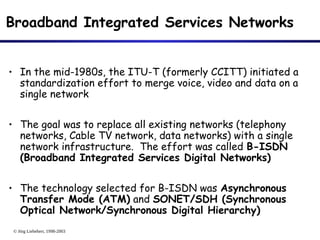
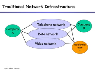
Broadband Integrated Services Networks
• In the mid-1980s, the ITU-T (formerly CCITT) initiated a
standardization effort to merge voice, video and data on a
single network
• The goal was to replace all existing networks (telephony
networks, Cable TV network, data networks) with a single
network infrastructure. The effort was called B-ISDN
(Broadband Integrated Services Digital Networks)
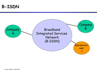
• The technology selected for B-ISDN was Asynchronous
Transfer Mode (ATM) and SONET/SDH (Synchronous
Optical Network/Synchronous Digital Hierarchy)
- 5.
© Jörg Liebeherr,1998-2003
Traditional Network Infrastructure
Company
A
Company
B
Telephone network
Data network
Residential
user
x
Video network
- 6.
© Jörg Liebeherr,1998-2003
B-ISDN
Company
A
Company
B
Residential
user
x
Broadband
Integrated Services
Network
(B-ISDN)
- 7.
© Jörg Liebeherr,1998-2003
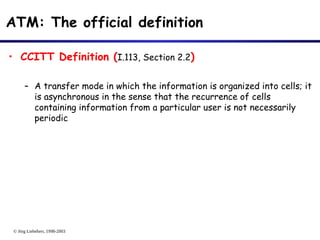
ATM: The official definition
• CCITT Definition (I.113, Section 2.2)
– A transfer mode in which the information is organized into cells; it
is asynchronous in the sense that the recurrence of cells
containing information from a particular user is not necessarily
periodic
- 8.
© Jörg Liebeherr,1998-2003
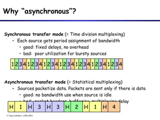
Why “asynchronous”?
Synchronous transfer mode (= Time division multiplexing)
– Each source gets period assignment of bandwidth
• good: fixed delays, no overhead
• bad: poor utilization for bursty sources
Asynchronous transfer mode (= Statistical multiplexing)
– Sources packetize data. Packets are sent only if there is data
• good: no bandwidth use when source is idle
• bad: packet headers, buffering, multiplexing delay
1 234 1 234 1 234 1 234 1 234 1 234 1 234
1
H 3
H 3
H 2
H 1
H 4
H
- 9.
© Jörg Liebeherr,1998-2003
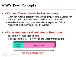
ATM’s Key Concepts
• ATM uses Virtual-Circuit Packet Switching
– ATM can reserve capacity for a virtual circuit. This is useful for
voice and video, which require a minimum level of service
– Overhead for setting up a connection is expensive if data
transmission is short (e.g., web browsing)
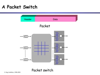
• ATM packets are small and have a fixed sized
– Packets in ATM are called cells
– Small packets are good for voice and video transmissions
Header
(5 byte)
Data (48 byte)
Cell is 53 byte long
- 10.
© Jörg Liebeherr,1998-2003
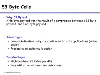
53 Byte Cells
• Why 53 Bytes?
A 48 byte payload was the result of a compromise between a 32 byte
payload and a 64 byte payload
• Advantages
– Low packetization delay for continuous bit rate applications (video,
audio)
– Processing at switches is easier
• Disadvantages
– High overhead (5 Bytes per 48)
– Poor utilization at lower line rates links
- 11.
© Jörg Liebeherr,1998-2003
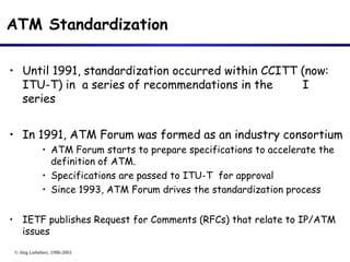
ATM Standardization
• Until 1991, standardization occurred within CCITT (now:
ITU-T) in a series of recommendations in the I
series
• In 1991, ATM Forum was formed as an industry consortium
• ATM Forum starts to prepare specifications to accelerate the
definition of ATM.
• Specifications are passed to ITU-T for approval
• Since 1993, ATM Forum drives the standardization process
• IETF publishes Request for Comments (RFCs) that relate to IP/ATM
issues
- 12.
© Jörg Liebeherr,1998-2003
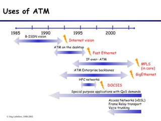
Uses of ATM
1985 1990 1995 2000
B-ISDN vision
ATM on the desktop
IP-over- ATM
ATM Enterprise backbones
Fast Ethernet
MPLS
(in core)
Internet vision
GigEthernet
Special purpose applications with QoS demands
Access Networks (xDSL)
Frame Relay transport
Voice trunking
DOCSIS
HFC networks
- 13.
- 14.
© Jörg Liebeherr,1998-2003
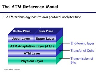
The ATM Reference Model
• ATM technology has its own protocol architecture
Physical Layer
ATM Layer
ATM Adaptation Layer (AAL)
Upper Layer Upper Layer
Control Plane User Plane
Transmission of
Bits
Transfer of Cells
End-to-end layer
- 15.
© Jörg Liebeherr,1998-2003
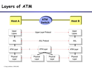
Layers of ATM
AAL
ATM Layer
Physical
Layer
Physical
Layer
Physical
Layer
ATM Layer
AAL
ATM Layer
Physical
Layer
AAL Protocol
l
Upper
Layers
Upper
Layers
Upper Layer Protocol
Host A
ATM
Switch
Host B
- 16.
© Jörg Liebeherr,1998-2003
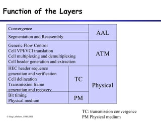
Function of the Layers
Convergence
AAL
Segmentation and Reassembly
Generic Flow Control
Cell VPI/VCI translation
Cell multiplexing and demultiplexing
Cell header generation and extraction
ATM
HEC header sequence
generation and verification
Cell delineation
Transmission frame
generation and recovery
Bit timing
Physical medium
TC
PM
Physical
TC: transmission convergence
PM Physical medium
- 17.
© Jörg Liebeherr,1998-2003
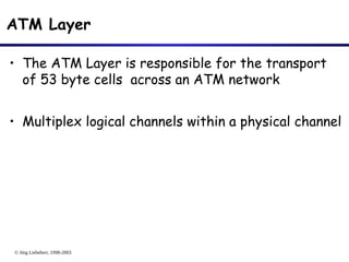
ATM Layer
• The ATM Layer is responsible for the transport
of 53 byte cells across an ATM network
• Multiplex logical channels within a physical channel
- 18.
© Jörg Liebeherr,1998-2003
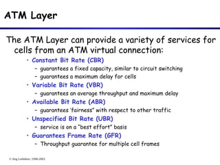
ATM Layer
The ATM Layer can provide a variety of services for
cells from an ATM virtual connection:
• Constant Bit Rate (CBR)
– guarantees a fixed capacity, similar to circuit switching
– guarantees a maximum delay for cells
• Variable Bit Rate (VBR)
– guarantees an average throughput and maximum delay
• Available Bit Rate (ABR)
– guarantees ‘fairness” with respect to other traffic
• Unspecified Bit Rate (UBR)
– service is on a “best effort” basis
• Guarantees Frame Rate (GFR)
– Throughput guarantee for multiple cell frames
- 19.
© Jörg Liebeherr,1998-2003
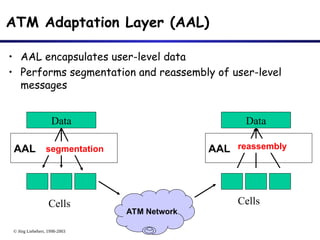
ATM Adaptation Layer (AAL)
• AAL encapsulates user-level data
• Performs segmentation and reassembly of user-level
messages
Data
AAL
Data
AAL
Cells Cells
ATM Network
segmentation reassembly
- 20.
- 21.
© Jörg Liebeherr,1998-2003
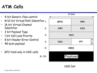
ATM Cells
• 4-bit Generic flow control
• 8/12 bit Virtual Path Identifier
• 16 bit Virtual Channel
Identifier
• 3 bit Payload Type
• 1 bit Cell Loss Priority
• 8 bit Header Error Control
• 48 byte payload
• GFC field only in UNI cells
VCI
8 bits
GFC VPI
VPI VCI
VCI PT
C
L
P
HEC
1
2
3
4
5
Payload
6- 53
UNI Cell
- 22.
© Jörg Liebeherr,1998-2003
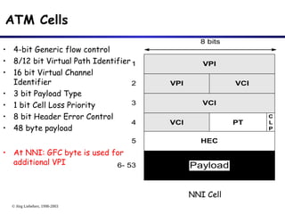
ATM Cells
• 4-bit Generic flow control
• 8/12 bit Virtual Path Identifier
• 16 bit Virtual Channel
Identifier
• 3 bit Payload Type
• 1 bit Cell Loss Priority
• 8 bit Header Error Control
• 48 byte payload
• At NNI: GFC byte is used for
additional VPI
VCI
8 bits
VPI VCI
VCI PT
C
L
P
HEC
1
2
3
4
5
Payload
6- 53
VPI
NNI Cell
- 23.
- 24.
- 25.
© Jörg Liebeherr,1998-2003
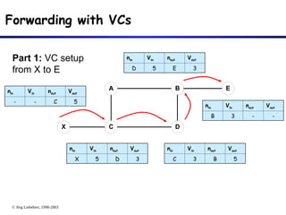
Forwarding with VCs
X
E
A
C
B
D
nin Vin nout Vout
- - C 5
nin Vin nout Vout
X 5 D 3
nin Vin nout Vout
C 3 B 5
nin Vin nout Vout
D 5 E 3
nin Vin nout Vout
B 3 - -
Part 1: VC setup
from X to E
- 26.
© Jörg Liebeherr,1998-2003
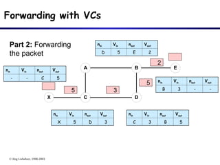
Forwarding with VCs
X
E
A
C
B
D
nin Vin nout Vout
- - C 5
nin Vin nout Vout
X 5 D 3
nin Vin nout Vout
C 3 B 5
nin Vin nout Vout
D 5 E 2
nin Vin nout Vout
B 3 - -
5
5
3
2
Part 2: Forwarding
the packet
- 27.
© Jörg Liebeherr,1998-2003
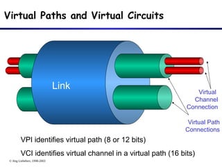
Virtual Paths and Virtual Circuits
Virtual Path
Connections
Virtual
Channel
Connection
VPI identifies virtual path (8 or 12 bits)
VCI identifies virtual channel in a virtual path (16 bits)
Link
- 28.
© Jörg Liebeherr,1998-2003
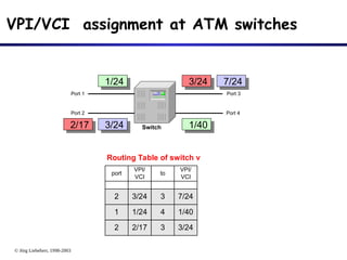
3/24
3
2/17
2
7/24
3
3/24
2
1/40
4
1/24
1
Routing Table of switch v
port
VPI/
VCI
to
VPI/
VCI
Port 1
Port 2
Port 3
Port 4
Switch
VPI/VCI assignment at ATM switches
1/24 7/24
3/24 1/40
3/24
2/17
- 29.
- 30.
© Jörg Liebeherr,1998-2003
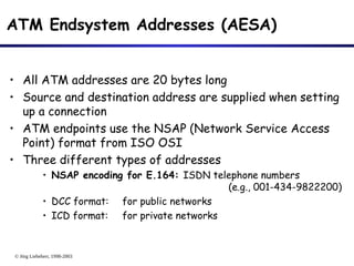
ATM Endsystem Addresses (AESA)
• All ATM addresses are 20 bytes long
• Source and destination address are supplied when setting
up a connection
• ATM endpoints use the NSAP (Network Service Access
Point) format from ISO OSI
• Three different types of addresses
• NSAP encoding for E.164: ISDN telephone numbers
(e.g., 001-434-9822200)
• DCC format: for public networks
• ICD format: for private networks
- 31.
© Jörg Liebeherr,1998-2003
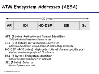
ATM Endsystem Addresses (AESA)
AFI (1 byte): Authority and Format Identifier
Tells which addressing scheme to use
IDI (2-8 bytes): Initial Domain Identifier
Identifies a domain within scope of addressing authority
HO-DSP (4-10 bytes): High-order bits of domain specific part
similar to network prefix of IP address
ESI (6 bytes): Endsystem identifier
similar to host number of IP address
SEL (1 byte): Selector
for endsystem use only
AFI
20 bytes
IDI HO-DSP ESI Sel
- 32.
© Jörg Liebeherr,1998-2003
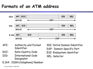
Formats of an ATM address
AFI: Authority and Format
Identifier
DCC: Data Country Code
ICD: International Code
Designator
E.164: ISDN (telephone) Number
DSP
AFI DCC ESI SEL
DCC
AFI=39
DSP
AFI ICD ESI SEL
ICD
AFI=47
DSP
AFI ICD ESI SEL
E.164
AFI=45
IDI: Initial Domain Identifier
DSP: Domain Specific Part
ESI: Endsystem identifier
SEL: Selector
- 33.
© Jörg Liebeherr,1998-2003
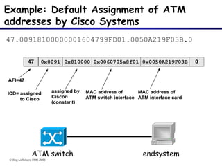
Example: Default Assignment of ATM
addresses by Cisco Systems
47.00918100000001604799FD01.0050A219F03B.0
47 0x0091 0x810000
AFI=47
ICD= assigned
to Cisco
assigned by
Ciscon
(constant)
0x0060705a8f01 0x0050A219F03B
MAC address of
ATM switch interface
MAC address of
ATM interface card
0
ATM switch endsystem
- 34.
© Jörg Liebeherr,1998-2003
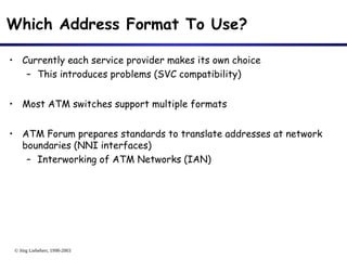
Which Address Format To Use?
• Currently each service provider makes its own choice
– This introduces problems (SVC compatibility)
• Most ATM switches support multiple formats
• ATM Forum prepares standards to translate addresses at network
boundaries (NNI interfaces)
– Interworking of ATM Networks (IAN)
- 35.
© Jörg Liebeherr,1998-2003
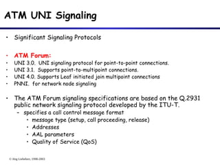
ATM UNI Signaling
• Significant Signaling Protocols
• ATM Forum:
• UNI 3.0. UNI signaling protocol for point-to-point connections.
• UNI 3.1. Supports point-to-multipoint connections.
• UNI 4.0. Supports Leaf initiated join multipoint connections
• PNNI. for network node signaling
• The ATM Forum signaling specifications are based on the Q.2931
public network signaling protocol developed by the ITU-T.
– specifies a call control message format
• message type (setup, call proceeding, release)
• Addresses
• AAL parameters
• Quality of Service (QoS)
- 36.
© Jörg Liebeherr,1998-2003
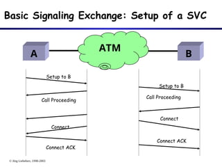
Basic Signaling Exchange: Setup of a SVC
A
Setup to B
Call Proceeding
Setup to B
Connect
Connect
Connect ACK
Connect ACK
B
ATM
Call Proceeding
- 37.
© Jörg Liebeherr,1998-2003
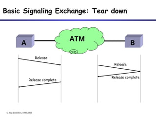
Release
Release
Release complete
Release complete
Basic Signaling Exchange: Tear down
A B
ATM
- 38.
- 39.
© Jörg Liebeherr,1998-2003
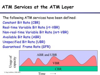
ATM Services at the ATM Layer
The following ATM services have been defined:
Constant Bit Rate (CBR)
Real-time Variable Bit Rate (rt-VBR)
Non-real-time Variable Bit Rate (nrt-VBR)
Available Bit Rate (ABR)
Unspecified Bit Rate (UBR)
Guaranteed Frame Rate (GFR)
Time
Usa
ge
of
cap
acit
y
CBR
VBR
ABR and UBR
- 40.
© Jörg Liebeherr,1998-2003
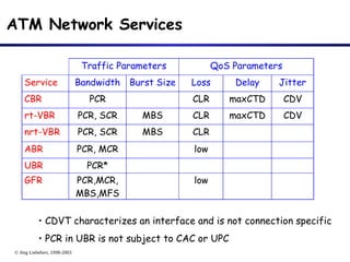
ATM Network Services
Traffic Parameters QoS Parameters
Service Bandwidth Burst Size Loss Delay Jitter
CBR PCR CLR maxCTD CDV
rt-VBR PCR, SCR MBS CLR maxCTD CDV
nrt-VBR PCR, SCR MBS CLR
ABR PCR, MCR low
UBR PCR*
GFR PCR,MCR,
MBS,MFS
low
• CDVT characterizes an interface and is not connection specific
• PCR in UBR is not subject to CAC or UPC
- 41.
© Jörg Liebeherr,1998-2003
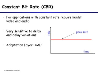
Constant Bit Rate (CBR)
• For applications with constant rate requirements:
video and audio
• Very sensitive to delay
and delay variations
• Adaptation Layer: AAL1
time
rate
peak rate
- 42.
© Jörg Liebeherr,1998-2003
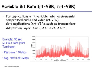
Variable Bit Rate (rt-VBR, nrt-VBR)
• For applications with variable rate requirements:
compressed audio and video (rt-VBR)
data applications (nrt-VBR), such as transactions
• Adaptation Layer: AAL2, AAL 3 /4, AAL5
0
2000
4000
6000
8000
10000
12000
14000
16000
0 100 200 300 400 500 600 700 800 900 1000
Frame number
T
r
a
f
f
i
c
Example: 30 sec
MPEG-1 trace (from
Terminator)
• Peak rate: 1.9 Mbps
• Avg. rate: 0.261 Mbps
- 43.
© Jörg Liebeherr,1998-2003
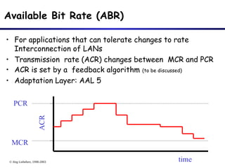
Available Bit Rate (ABR)
• For applications that can tolerate changes to rate
Interconnection of LANs
• Transmission rate (ACR) changes between MCR and PCR
• ACR is set by a feedback algorithm (to be discussed)
• Adaptation Layer: AAL 5
MCR
PCR
time
ACR
- 44.
© Jörg Liebeherr,1998-2003
Unspecified Bit Rate (UBR)
• “Best effort service”
– No bandwidth, loss, or delay guarantees
– UBR gets the bandwidth that is not used by CBR, VBR,
ABR
• No UPC and no feedback
• Applications: Non-critical data applications (file transfer,
web access, etc.)
• Adaptation Layer: AAL5
- 45.
© Jörg Liebeherr,1998-2003
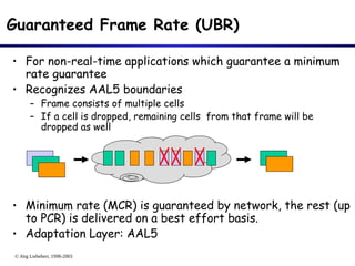
Guaranteed Frame Rate (UBR)
• For non-real-time applications which guarantee a minimum
rate guarantee
• Recognizes AAL5 boundaries
– Frame consists of multiple cells
– If a cell is dropped, remaining cells from that frame will be
dropped as well
• Minimum rate (MCR) is guaranteed by network, the rest (up
to PCR) is delivered on a best effort basis.
• Adaptation Layer: AAL5
- 46.
- 47.
© Jörg Liebeherr,1998-2003
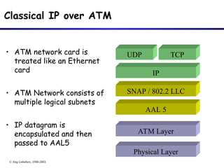
Classical IP over ATM
• ATM network card is
treated like an Ethernet
card
• ATM Network consists of
multiple logical subnets
• IP datagram is
encapsulated and then
passed to AAL5
AAL 5
ATM Layer
Physical Layer
IP
SNAP / 802.2 LLC
UDP TCP
- 48.
© Jörg Liebeherr,1998-2003
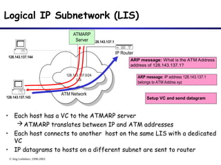
Logical IP Subnetwork (LIS)
• Each host has a VC to the ATMARP server
ATMARP translates between IP and ATM addresses
• Each host connects to another host on the same LIS with a dedicated
VC
• IP datagrams to hosts on a different subnet are sent to router
ATM Network
IP Router
128.143.137.1
128.143.137.144
128.143.137.143
ATMARP
Server
128.143.137.0/24
LIS
ARP message: What is the ATM Address
address of 128.143.137.1?
ARP message: IP address 128.143.137.1
belongs to ATM Addrss xyz
Setup VC and send datagram
- 49.
© Jörg Liebeherr,1998-2003
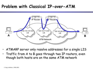
Problem with Classical IP-over-ATM
• ATMARP server only resolve addresses for a single LIS
• Traffic from A to B goes through two IP routers, even
though both hosts are on the same ATM network
ATM Network
IP Router
A
128.143.137.0/24
LIS
128.143.71.0/24
LIS
B
128.143.28.0/24
LIS
IP Router