The document discusses electric and magnetic fields, including:
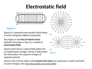
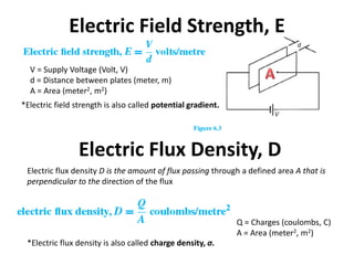
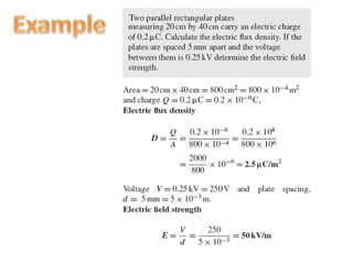
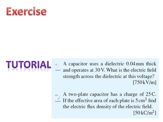
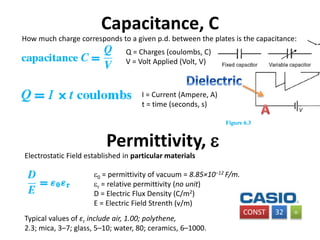
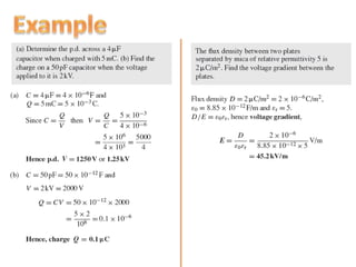
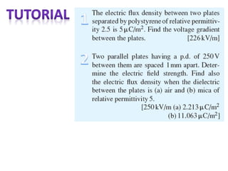
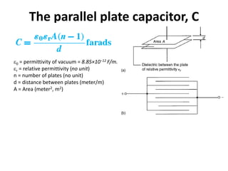
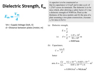
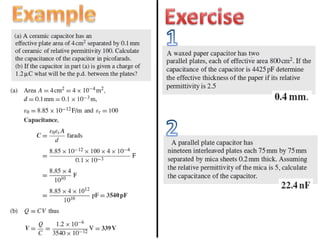
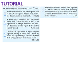
- An electric field is established between two parallel metal plates charged to different potentials.
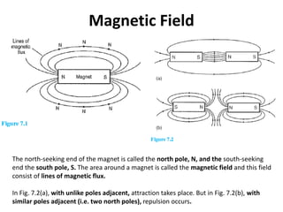
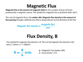
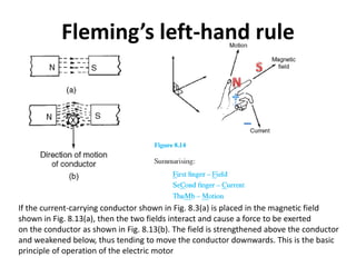
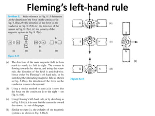
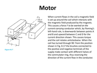
- Magnetic field lines originate and terminate on magnetic poles. Unlike poles attract while like poles repel.
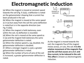
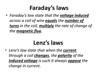
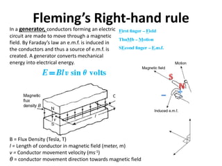
- Electromagnetic induction occurs when a changing magnetic field induces an electric current in a conductor. The direction of the induced current opposes the change according to Lenz's law.