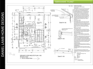
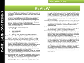
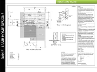
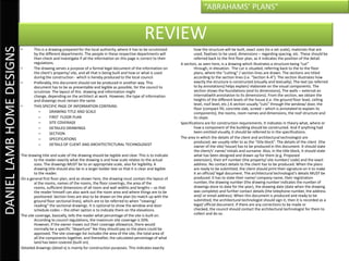
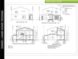
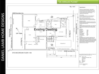
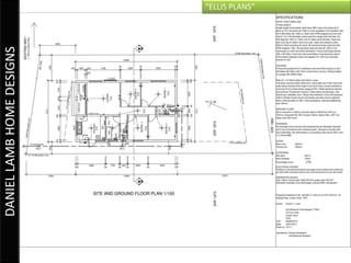
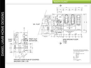
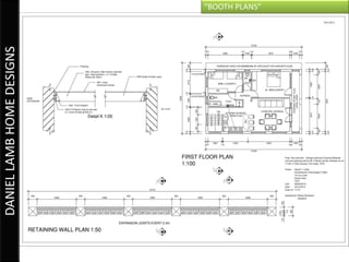
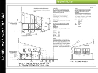
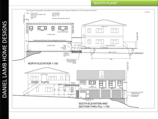
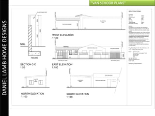
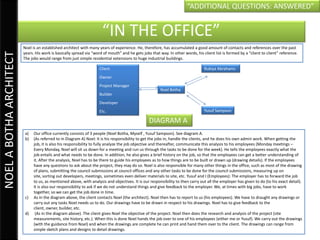
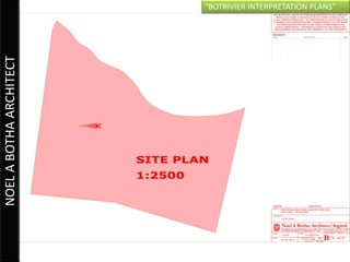
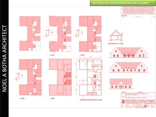
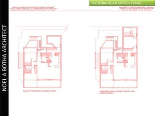
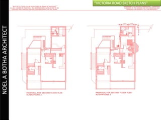
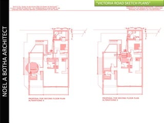
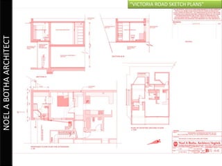
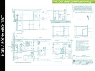
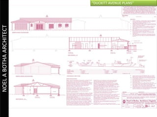
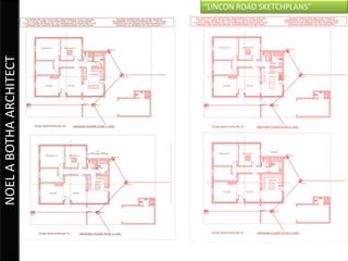
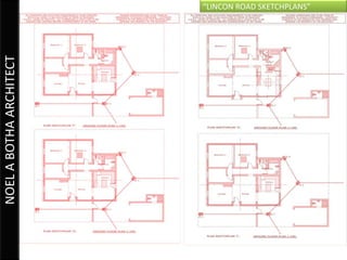
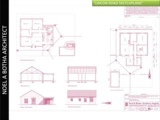
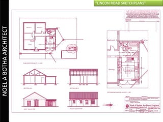
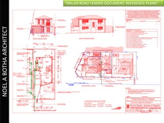
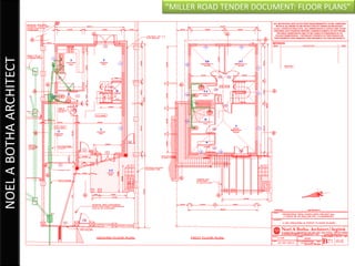
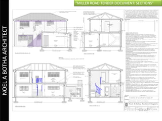
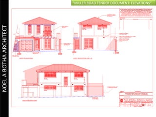
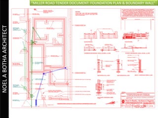
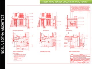
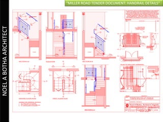
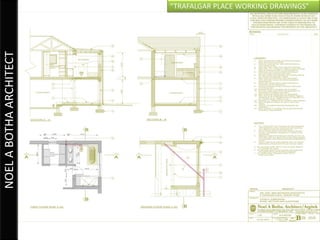
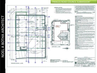
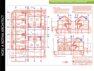
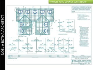
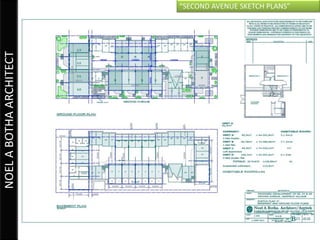
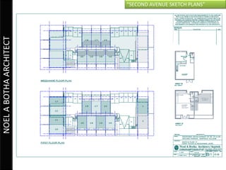
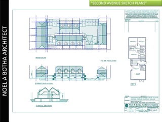
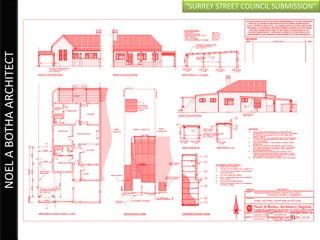
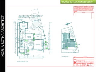
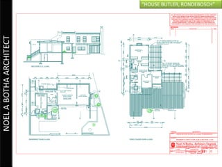
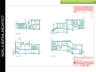
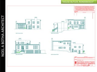
“PORTFOLIO”


                            LETTERS TO EMPLOYERS
RUKIYA ABRAHAMS 210032502
DANIEL LAMB HOME DESIGNS   “SUMMARY OF DRAWINGS”
“ADDITIONAL QUESTIONS: ANSWERED”


                                                           “IN THE OFFICE”
DANIEL LAMB HOME DESIGNS


                           DRAWING REFERENCE SYSTEM
                                                 EXTERNAL                    PROJECT FOLDER:
                                                 HARDRIVE:                   Eg. “Van Schoor            THE AUTOCAD
                                                 We store all our            Plans” (Folders            FILE:
                                                 projects on an              named according            Eg. “Van Schoor
                                                 external                    to client’s                Plans.dwg” file
                                                 hardrive.                   surnames


                           The company doesn’t have any form of media advertisement, however, it is advertised via ‘word-of-mouth’, via
                           business cards, or referrals by clients. Most of the work we source is from around the area he lives.

                           a) Currently it’s only Mr Lamb and I in this company. Originally he had worked alone for many years. I was the first
                              student to work under him. He was my high school Civil Technology educator. When I finished my first year of
                              studies I started working for him (as he also had his own practice as an architectural technologist)
                           b) Mr Lamb generally sources all of the work. He also does his own admin work and handles the clients. He also does
                              the draught work of projects. My job is basically to assist and draught up projects. In some cases I assist with the
                              designing and admin work.
                           c) Clients report to Mr Lamb and he then briefs the project to me. We would either work together on one
                              project, where discussion would happen throughout the whole project, or he would send me home with a project
                              to finish and he would tweak it after.
                           d) In general, Mr Lamb is responsible for handling the clients. He briefs me on what the client wants. Then we work on
                              the draughting together. In certain cases he will involve me with the admin work such as council submission forms.
DANIEL LAMB HOME DESIGNS   “ABRAHAMS’ PLANS”
“ABRAHAMS’ PLANS”


                                                                                                       REVIEW
DANIEL LAMB HOME DESIGNS

                           •       This is a drawing prepared for the local authority, where it has to be scrutinized           area and where things are to be positioned. Section lines are also to be drawn
                                   by the different departments. The people in these respective departments will                on the plan, which are to be referred to when “viewing/ reading” the sectional
                                   then check and investigate if all the information on this page is correct to their           drawings. Dotted lines are to indicate any demolished work and a different set
                                   regulations.                                                                                 of dotted or dashed lines are to indicate lintels. All existing components of the
                           •       The drawing serves a purpose of a formal legal document of the information                   house, when printed, are indicated by colouring them in black. It is optional to
                                   on the client’s property/ site, and all that is being built and how or what is               show the window and door schedule codes – the other option is to indicate
                                   used during the construction - which is hereby produced to the local council.                them on the elevations.
                           •       Preferably, this document should not be produced in another way. This                Detailed drawings (details W, R, D) are mainly for construction purposes. This indicates
                                   document has to be as presentable and legible as possible, for the council to                exactly how the structure will be built, exact sizes (to a set scale), materials
                                   scrutinize. The layout of this drawing and information might                                 that are used, fixatives to be used, dimensions – regarding timber spacing, etc.
                                   change, depending on the architect at work. However, the type of information                 These should be referred back to the ground floor plan, as it indicates the
                                   and drawings must remain the same.                                                           position of the detail.
                           •       THIS SPECIFIC PAGE OF INFORMATION CONTAINS:                                          Specifications are for construction requirements. It indicates in theory what, where or
                                      –       SITE PLAN                                                                         how a component of the building should be constructed. And if anything had
                                                                                                                                been omitted visually, it should be referred to in the specifications.
                                      –       GROUND FLOOR PLAN
                                                                                                                        The area in which the details of the client and architectural technologist are
                                      –       DETAILED DRAWINGS                                                                 produced, we usually refer to as the “title block”. The details of the client (the
                                      –       SPECIFICATIONS                                                                    owner of the site/ house) has to be produced in this document. It should state
                                      –       DETAILS OF CLIENT AND ARCHITECTECTURAL TECHNOLOGIST                               the client/s’ name/ initials and surname. Also, in the title block, it should state
                           The site plan and ground floor plan had been merged. However in some cases it is                     what has been designed and drawn up for them (e.g. Proposed
                                   separated. In this case it had been merged to save space and the overall                     extension), their erf number (the property/ site number/ code) and the exact
                                   amount of pages used. This information had been prepared on an A3 page.                      address. No contact details to the client has to be produced. When the plans
                           Generally, the information on the site plan MUST contain – as seen here – a north                    are ready to be submitted, the client should print their signature on it to make
                                   point (shows where and how the house is orientated), boundary lines(and its                  it an official/ legal document. The architectural technologist’s details MUST be
                                   dimensions), building lines (and its dimensions – these dimensions are to                    produced. It has to state their name/ company name, their registration
                                   indicate to council exactly what land, in relation to the surrounding                        number, the drawing number (the drawing number indicates the number of
                                   properties, belongs to the owner and where there are restrictions for them to                drawings done to date for the year), the drawing date (date when the drawing
                                   build), it should show buildings or components already exist on the site.                    was complete) and further contact details (the telephone number, the address
                                   However it is shown by colour – when the plan is printed – (i.e. existing                    and/ or email address). When this document is produced and ready to be
                                   components on the common drawn site plan is not coloured in). Information                    submitted, the architectural technologist should sign it, then it is recorded as a
                                   also to be included on the drawing is the drawing title, erf                                 legal/ official document. If there are any corrections to be made or
                                   number, address, distance to nearest crossing (road), drainage plan, boundary                checked, the council should contact the architectural technologist for them to
                                   walls, distance of offset from the house to the boundary, carriage-way-crossing              collect and do so.
                                   indicated, the position of the building.
                           The ground floor plan was drawn with the site plan to save paper space. On a general
                                   ground floor plan, and as shown here, the drawing must contain the layout of
                                   al the rooms, names of the rooms, the floor coverings, the area of the
                                   rooms, sufficient dimensions of all room and wall (including boundary walls)
                                   widths and lengths – so that the reader himself can also work out the room
DANIEL LAMB HOME DESIGNS   “ABRAHAMS’ PLANS”
“ABRAHAMS’ PLANS”


                                                                                                        REVIEW
DANIEL LAMB HOME DESIGNS

                           •       This is a drawing prepared for the local authority, where it has to be scrutinized             how the structure will be built, exact sizes (to a set scale), materials that are
                                   by the different departments. The people in these respective departments will                  used, fixatives to be used, dimensions – regarding spacing, etc. These should be
                                   then check and investigate if all the information on this page is correct to their             referred back to the first floor plan, as it indicates the position of the detail.
                                   regulations.                                                                           A section, as seen here, is a drawing which illustrates a structure being “cut”
                           •       The drawing serves a purpose of a formal legal document of the information on                  through, in elevation. The cut is situated, referring back to the to the floor
                                   the client’s property/ site, and all that is being built and how or what is used               plans, where the “cutting” / section lines are drawn. The sections are titled
                                   during the construction - which is hereby produced to the local council.                       according to the section lines (i.e. “Section A-A”). The section illustrates how
                           •       Preferably, this document should not be produced in another way. This                          exactly the structure is constructed (visually and textually). The text (as referred
                                   document has to be as presentable and legible as possible, for the council to                  to by annotations) helps explain/ elaborate on the visual components. The
                                   scrutinize. The layout of this drawing and information might                                   section shows the foundations (and its dimensions), The walls – external an
                                   change, depending on the architect at work. However, the type of information                   internal(with annotation to its dimensions). From the section, we obtain the
                                   and drawings must remain the same.                                                             heights of the different levels of the house (i.e. the ground floor level, ceiling
                           •       THIS SPECIFIC PAGE OF INFORMATION CONTAINS:                                                    level, roof level, etc.) A section usually “cuts” through the window/ door, the
                                                                                                                                  floor (compact fill, concrete slab, screed – which is annotated to explain its
                                      –       DRAWING TITLE AND SCALE                                                             components), the rooms, room names and dimensions, the roof structure and
                                      –       FIRST FLOOR PLAN                                                                    its slope.
                                      –       SITE COVERAGE                                                               Specifications are for construction requirements. It indicates in theory what, where or
                                      –       DETAILED DRAWINGS                                                                   how a component of the building should be constructed. And if anything had
                                      –       SECTIION                                                                            been omitted visually, it should be referred to in the specifications.
                                      –       SPECIFICATIONS                                                              The area in which the details of the client and architectural technologist are
                                                                                                                                  produced, we usually refer to as the “title block”. The details of the client (the
                                      –       DETAILS OF CLIENT AND ARCHITECTECTURAL TECHNOLOGIST                                 owner of the site/ house) has to be produced in this document. It should state
                                                                                                                                  the client/s’ name/ initials and surname. Also, in the title block, it should state
                           The drawing title and scale of the drawing should be legible and clear. This is to indicate            what has been designed and drawn up for them (e.g. Proposed
                                   to the reader exactly what the drawing is and how scale relates to the actual                  extension), their erf number (the property/ site number/ code) and the exact
                                   sizes. The drawings MUST be to an appropriate scale, also for legibility. A                    address. No contact details to the client has to be produced. When the plans
                                   drawing title should also be in a larger bolder text so that it is clear and legible           are ready to be submitted, the client should print their signature on it to make
                                   to the reader.                                                                                 it an official/ legal document. The architectural technologist’s details MUST be
                           On a general first floor plan, and as shown here, the drawing must contain the layout of               produced. It has to state their name/ company name, their registration
                                   al the rooms, names of the rooms, the floor coverings, the area of the                         number, the drawing number (the drawing number indicates the number of
                                   rooms, sufficient dimensions of all room and wall widths and lengths – so that                 drawings done to date for the year), the drawing date (date when the drawing
                                   the reader himself can also work out the room area and where things are to be                  was complete) and further contact details (the telephone number, the address
                                   positioned. Section lines are also to be drawn on the plan (to match up with the               and/ or email address). When this document is produced and ready to be
                                   ground floor sectional lines), which are to be referred to when “viewing/                      submitted, the architectural technologist should sign it, then it is recorded as a
                                   reading” the sectional drawings. It is optional to show the window and door                    legal/ official document. If there are any corrections to be made or
                                   schedule codes – the other option is to indicate them on the elevations.                       checked, the council should contact the architectural technologist for them to
                           The site coverage, basically, tells the reader what percentage of the site is built on.                collect and do so.
                                   According to council regulations, the maximum site coverage is 50%.
                                   However, if the owner maxes out their coverage allowance, there would
                                   normally be a specific “departure” fee they should pay so the plans could be
                                   approved. The site coverage list includes the area of the site, the total area of
                                   all the components together, and thereafter, the calculated percentage of what
                                   land has been covered (built on).
                           Detailed drawings (detail x) is mainly for construction purposes. This indicates exactly
DANIEL LAMB HOME DESIGNS   “ABRAHAMS’ PLANS”
“ABRAHAMS’ PLANS”


                                                                                                      REVIEW
DANIEL LAMB HOME DESIGNS

                           •      This is a drawing prepared for the local authority, where it has to be                      depends on the orientation of the house (e.g. East elevation – means it’s
                                  scrutinized by the different departments. The people in these respective                    facing the east direction). The elevation should contain the position of the
                                  departments will then check and investigate if all the information on this page             NGL (natural ground level), the position of the ground floor level (indicated on
                                  is correct to their regulations.                                                            the drawing by “GFL”), the first floor level (indicated on the drawing by
                           •      The drawing serves a purpose of a formal legal document of the information                  “FFL”), the position of the roof (since it is a parapet roof – in the drawing – the
                                  on the client’s property/ site, and all that is being built and how or what is              roof position is indicated by a dashed line), it should indicate the wall finish
                                  used during the construction - which is hereby produced to the local council.               (e.g. plastered & painted or face-brick, etc.). The elevation is usually produced
                           •      Preferably, this document should not be produced in another way. This                       from the sections and plan to obtain the heights and positions of components
                                  document has to be as presentable and legible as possible, for the council to               (e.g. such as window positions, or floor levels).
                                  scrutinize. The layout of this drawing and information might                        Specifications are for construction requirements. It indicates in theory what, where or
                                  change, depending on the architect at work. However, the type of information                how a component of the building should be constructed. And if anything had
                                  and drawings must remain the same.                                                          been omitted visually, it should be referred to in the specifications.
                           •      THIS SPECIFIC PAGE OF INFORMATION CONTAINS:                                         The area in which the details of the client and architectural technologist are
                                      –      DRAWING TITLES AND SCALES                                                        produced, we usually refer to as the “title block”. The details of the client (the
                                                                                                                              owner of the site/ house) has to be produced in this document. It should state
                                      –      SECTIION                                                                         the client/s’ name/ initials and surname. Also, in the title block, it should state
                                      –      ELEVATIONS                                                                       what has been designed and drawn up for them (e.g. Proposed
                                      –      SPECIFICATIONS                                                                   extension), their erf number (the property/ site number/ code) and the exact
                                      –      DETAILS OF CLIENT AND ARCHITECTECTURAL TECHNOLOGIST                              address. No contact details to the client has to be produced. When the plans
                                                                                                                              are ready to be submitted, the client should print their signature on it to make
                                                                                                                              it an official/ legal document. The architectural technologist’s details MUST be
                           The drawing title and scale of the drawing should be legible and clear. This is to                 produced. It has to state their name/ company name, their registration
                                   indicate to the reader exactly what the drawing is and how scale relates to the            number, the drawing number (the drawing number indicates the number of
                                   actual sizes. The drawings MUST be to an appropriate scale, also for legibility.           drawings done to date for the year), the drawing date (date when the drawing
                                   A drawing title should also be in a larger bolder text so that it is clear and             was complete) and further contact details (the telephone number, the
                                   legible to the reader.                                                                     address and/ or email address). When this document is produced and ready
                           A section, as seen here, is a drawing which illustrates a structure being “cut”                    to be submitted, the architectural technologist should sign it, then it is
                                   through, in elevation. The cut is situated, referring back to the to the floor             recorded as a legal/ official document. If there are any corrections to be made
                                   plans, where the “cutting” / section lines are drawn. The sections are titled              or checked, the council should contact the architectural technologist for them
                                   according to the section lines (i.e. “Section A-A”). The section illustrates how           to collect and do so.
                                   exactly the structure is constructed (visually and textually). The text (as
                                   referred to by annotations) helps explain/ elaborate on the visual
                                   components. The section shows the foundations (and its dimensions), The
                                   walls – external an internal(with annotation to its dimensions). From the
                                   section, we obtain the heights of the different levels of the house (i.e. the
                                   ground floor level, ceiling level, roof level, etc.) A section usually “cuts”
                                   through the window/ door, the floor (compact fill, concrete slab, screed –
                                   which is annotated to explain its components), the rooms, room names and
                                   dimensions, the roof structure and its slope.
                           An elevation is a view of the house from its exterior. The title of the elevation
DANIEL LAMB HOME DESIGNS   “ABRAHAMS’ PLANS”
“ABRAHAMS’ PLANS”


                                                                                                       7
                                                                                                     REVIEW
DANIEL LAMB HOME DESIGNS

                           •      This is a drawing prepared for the local authority, where it has to be                    “FFL”), the position of the roof (since it is a parapet roof – in the drawing – the
                                  scrutinized by the different departments. The people in these respective                  roof position is indicated by a dashed line), it should indicate the wall finish
                                  departments will then check and investigate if all the information on this page           (e.g. plastered & painted or face-brick, etc.). The elevation is usually produced
                                  is correct to their regulations.                                                          from the sections and plan to obtain the heights and positions of components
                           •      The drawing serves a purpose of a formal legal document of the information                (e.g. such as window positions, or floor levels).
                                  on the client’s property/ site, and all that is being built and how or what is     The area in which the details of the client and architectural technologist are
                                  used during the construction - which is hereby produced to the local council.             produced, we usually refer to as the “title block”. The details of the client (the
                           •      Preferably, this document should not be produced in another way. This                     owner of the site/ house) has to be produced in this document. It should state
                                  document has to be as presentable and legible as possible, for the council to             the client/s’ name/ initials and surname. Also, in the title block, it should state
                                  scrutinize. The layout of this drawing and information might                              what has been designed and drawn up for them (e.g. Proposed
                                  change, depending on the architect at work. However, the type of information              extension), their erf number (the property/ site number/ code) and the exact
                                  and drawings must remain the same.                                                        address. No contact details to the client has to be produced. When the plans
                           •      THIS SPECIFIC PAGE OF INFORMATION CONTAINS:                                               are ready to be submitted, the client should print their signature on it to make
                                                                                                                            it an official/ legal document. The architectural technologist’s details MUST be
                                      –      DRAWING TITLES AND SCALES                                                      produced. It has to state their name/ company name, their registration
                                      –      DRAINAGE SECTIION                                                              number, the drawing number (the drawing number indicates the number of
                                      –      ELEVATIONS                                                                     drawings done to date for the year), the drawing date (date when the drawing
                                      –      DETAILS OF CLIENT AND ARCHITECTECTURAL TECHNOLOGIST                            was complete) and further contact details (the telephone number, the
                                                                                                                            address and/ or email address). When this document is produced and ready
                                                                                                                            to be submitted, the architectural technologist should sign it, then it is
                           The drawing title and scale of the drawing should be legible and clear. This is to               recorded as a legal/ official document. If there are any corrections to be made
                                  indicate to the reader exactly what the drawing is and how scale relates to the           or checked, the council should contact the architectural technologist for them
                                  actual sizes. The drawings MUST be to an appropriate scale, also for legibility.          to collect and do so.
                                  A drawing title should also be in a larger bolder text so that it is clear and
                                  legible to the reader.
                           The drainage section is a drawing which explains how all the drainage connections
                                  work in the building and how it runs out of the building – to a main
                                  (municipal) connection. The section is always taken from the plan to plot out
                                  distances and positions of connections. Here you will calculate exactly how far
                                  rodding eyes (RE), inspection chambers (IC), manholes (MH) are apart from
                                  each other, how deep they are, it states the slope the underground pipe is
                                  running at and the diameter and the material its made from. The calculations
                                  are mainly to obtain the depths and invert levels. Distances are measured on
                                  site and plotted on plan, and thereafter, plotted to the section.
                           An elevation is a view of the house from its exterior. The title of the elevation
                                  depends on the orientation of the house (e.g. East elevation – means it’s
                                  facing the east direction). The elevation should contain the position of the
                                  NGL (natural ground level), the position of the ground floor level (indicated on
                                  the drawing by “GFL”), the first floor level (indicated on the drawing by
DANIEL LAMB HOME DESIGNS   “DE ARAUJO PLANS”
“DE ARAUJO PLANS”


                                                                                                      REVIEW
DANIEL LAMB HOME DESIGNS

                           •       This is a drawing prepared for the local authority, where it has to be                     al the rooms, names of the rooms, the floor coverings, the area of the
                                   scrutinized by the different departments. The people in these respective                   rooms, sufficient dimensions of all room and wall (including boundary walls)
                                   departments will then check and investigate if all the information on this page            widths and lengths – so that the reader himself can also work out the room
                                   is correct to their regulations.                                                           area and where things are to be positioned. Section lines are also to be drawn
                           •       The drawing serves a purpose of a formal legal document of the information                 on the plan, which are to be referred to when “viewing/ reading” the
                                   on the client’s property/ site, and all that is being built and how or what is             sectional drawings. Dotted lines are to indicate any demolished work and a
                                   used during the construction - which is hereby produced to the local council.              different set of dotted or dashed lines are to indicate lintels. All existing
                           •       Preferably, this document should not be produced in another way. This                      components of the house, when printed, are indicated by colouring them in
                                   document has to be as presentable and legible as possible, for the council to              black. It is optional to show the window and door schedule codes – the other
                                   scrutinize. The layout of this             drawing and information might                   option is to indicate them on the elevations.
                                   change, depending on the architect at work. However, the type of information       Specifications are for construction requirements. It indicates in theory what, where or
                                   and drawings must remain the same.                                                         how a component of the building should be constructed. And if anything had
                           •       THIS SPECIFIC PAGE OF INFORMATION CONTAINS:                                                been omitted visually, it should be referred to in the specifications.
                                       –     DRAWING TITLES AND SCALES                                                The site coverage, basically, tells the reader what percentage of the site is built on.
                                                                                                                              According to council regulations, the maximum site coverage is 50%.
                                       –     SITE PLAN                                                                        However, if the owner maxes out their coverage allowance, there would
                                       –     GROUND FLOOR PLAN                                                                normally be a specific “departure” fee they should pay so the plans could be
                                       –     SPECIFICATIONS                                                                   approved. The site coverage list includes the area of the site, the total area of
                                       –     SITE COVERAGE                                                                    all the components together, and thereafter, the calculated percentage of
                                                                                                                              what land has been covered (built on).
                                       –     DETAILS OF CLIENT AND ARCHITECTECTURAL TECHNOLOGIST
                                                                                                                      The area in which the details of the client and architectural technologist are
                           The drawing title and scale of the drawing should be legible and clear. This is to                 produced, we usually refer to as the “title block”. The details of the client (the
                                   indicate to the reader exactly what the drawing is and how scale relates to the            owner of the site/ house) has to be produced in this document. It should state
                                   actual sizes. The drawings MUST be to an appropriate scale, also for legibility.           the client/s’ name/ initials and surname. Also, in the title block, it should state
                                   A drawing title should also be in a larger bolder text so that it is clear and             what has been designed and drawn up for them (e.g. Proposed
                                   legible to the reader.                                                                     extension), their erf number (the property/ site number/ code) and the exact
                           The site plan and ground floor plan had been merged. However in some cases it is                   address. No contact details to the client has to be produced. When the plans
                                   separated. In this case it had been merged to save space and the overall                   are ready to be submitted, the client should print their signature on it to make
                                   amount of pages used. This information had been prepared on an A3 page.                    it an official/ legal document. The architectural technologist’s details MUST be
                           Generally, the information on the site plan MUST contain – as seen here – a north                  produced. It has to state their name/ company name, their registration
                                   point (shows where and how the house is orientated), boundary lines(and its                number, the drawing number (the drawing number indicates the number of
                                   dimensions), building lines (and its dimensions – these dimensions are to                  drawings done to date for the year), the drawing date (date when the drawing
                                   indicate to council exactly what land, in relation to the surrounding                      was complete) and further contact details (the telephone number, the
                                   properties, belongs to the owner and where there are restrictions for them to              address and/ or email address). When this document is produced and ready
                                   build), it should show buildings or components already exist on the site.                  to be submitted, the architectural technologist should sign it, then it is
                                   However it is shown by colour – when the plan is printed – (i.e. existing                  recorded as a legal/ official document. If there are any corrections to be made
                                   components on the common drawn site plan is not coloured in). Information                  or checked, the council should contact the architectural technologist for them
                                   also to be included on the drawing is the drawing title, erf                               to collect and do so.
                                   number, address, distance to nearest crossing (road), drainage plan, boundary
                                   walls, distance of offset from the house to the boundary, carriage-way-
                                   crossing indicated, the position of the building.
                           The ground floor plan was drawn with the site plan to save paper space. On a general
                                   ground floor plan, and as shown here, the drawing must contain the layout of
DANIEL LAMB HOME DESIGNS   “DE ARAUJO PLANS”
“DE ARAUJO PLANS”


                                                                                                        REVIEW
DANIEL LAMB HOME DESIGNS

                           •       This is a drawing prepared for the local authority, where it has to be                        exactly the structure is constructed (visually and textually). The text (as
                                   scrutinized by the different departments. The people in these respective                      referred to by annotations) helps explain/ elaborate on the visual
                                   departments will then check and investigate if all the information on this page               components. The section shows the foundations (and its dimensions), The
                                   is correct to their regulations.                                                              walls – external an internal(with annotation to its dimensions). From the
                           •       The drawing serves a purpose of a formal legal document of the information                    section, we obtain the heights of the different levels of the house (i.e. the
                                   on the client’s property/ site, and all that is being built and how or what is                ground floor level, ceiling level, roof level, etc.) A section usually “cuts”
                                   used during the construction - which is hereby produced to the local council.                 through the window/ door, the floor (compact fill, concrete slab, screed –
                           •       Preferably, this document should not be produced in another way. This                         which is annotated to explain its components), the rooms, room names and
                                   document has to be as presentable and legible as possible, for the council to                 dimensions, the roof structure and its slope.
                                   scrutinize. The layout of this drawing and information might                          Detailed drawings (detail R, D, W) is mainly for construction purposes. This indicates
                                   change, depending on the architect at work. However, the type of information                  exactly how the structure will be built, exact sizes (to a set scale), materials
                                   and drawings must remain the same.                                                            that are used, fixatives to be used, dimensions – regarding spacing, etc. These
                           •       THIS SPECIFIC PAGE OF INFORMATION CONTAINS:                                                   should be referred back to the first floor plan, as it indicates the position of
                                                                                                                                 the detail.
                                       –      DRAWING TITLES AND SCALES
                                                                                                                         The area in which the details of the client and architectural technologist are
                                       –      ELEVATIONS                                                                         produced, we usually refer to as the “title block”. The details of the client (the
                                       –      SECTIONS                                                                           owner of the site/ house) has to be produced in this document. It should state
                                       –      DETAILED DRAWINGS                                                                  the client/s’ name/ initials and surname. Also, in the title block, it should state
                                       –      DETAILS OF CLIENT AND ARCHITECTECTURAL TECHNOLOGIST                                what has been designed and drawn up for them (e.g. Proposed
                           The drawing title and scale of the drawing should be legible and clear. This is to                    extension), their erf number (the property/ site number/ code) and the exact
                                   indicate to the reader exactly what the drawing is and how scale relates to the               address. No contact details to the client has to be produced. When the plans
                                   actual sizes. The drawings MUST be to an appropriate scale, also for legibility.              are ready to be submitted, the client should print their signature on it to make
                                   A drawing title should also be in a larger bolder text so that it is clear and                it an official/ legal document. The architectural technologist’s details MUST be
                                   legible to the reader.                                                                        produced. It has to state their name/ company name, their registration
                                                                                                                                 number, the drawing number (the drawing number indicates the number of
                           An elevation is a view of the house from its exterior. The title of the elevation                     drawings done to date for the year), the drawing date (date when the drawing
                                   depends on the orientation of the house (e.g. East elevation – means it’s                     was complete) and further contact details (the telephone number, the
                                   facing the east direction). The elevation should contain the position of the                  address and/ or email address). When this document is produced and ready
                                   NGL (natural ground level), the position of the ground floor level (indicated on              to be submitted, the architectural technologist should sign it, then it is
                                   the drawing by “GFL”), the first floor level (indicated on the drawing by                     recorded as a legal/ official document. If there are any corrections to be made
                                   “FFL”), the position of the roof (since it is a parapet roof – in the drawing – the           or checked, the council should contact the architectural technologist for them
                                   roof position is indicated by a dashed line), it should indicate the wall finish              to collect and do so.
                                   (e.g. plastered & painted or face-brick, etc.). The elevation is usually produced
                                   from the sections and plan to obtain the heights and positions of components
                                   (e.g. such as window positions, or floor levels).
                           A section, as seen here, is a drawing which illustrates a structure being “cut”
                                   through, in elevation. The cut is situated, referring back to the to the floor
                                   plans, where the “cutting” / section lines are drawn. The sections are titled
                                   according to the section lines (i.e. “Section A-A”). The section illustrates how
DANIEL LAMB HOME DESIGNS   “ELLIS PLANS”
“ELLIS PLANS”


                                                                                                     REVIEW
DANIEL LAMB HOME DESIGNS

                           •      This is a drawing prepared for the local authority, where it has to be                      al the rooms, names of the rooms, the floor coverings, the area of the
                                  scrutinized by the different departments. The people in these respective                    rooms, sufficient dimensions of all room and wall (including boundary walls)
                                  departments will then check and investigate if all the information on this page             widths and lengths – so that the reader himself can also work out the room
                                  is correct to their regulations.                                                            area and where things are to be positioned. Section lines are also to be drawn
                           •      The drawing serves a purpose of a formal legal document of the information                  on the plan, which are to be referred to when “viewing/ reading” the sectional
                                  on the client’s property/ site, and all that is being built and how or what is              drawings. Dotted lines are to indicate any demolished work and a different set
                                  used during the construction - which is hereby produced to the local council.               of dotted or dashed lines are to indicate lintels. All existing components of the
                           •      Preferably, this document should not be produced in another way. This                       house, when printed, are indicated by colouring them in black. It is optional to
                                  document has to be as presentable and legible as possible, for the council to               show the window and door schedule codes – the other option is to indicate
                                  scrutinize. The layout of this drawing and information might                                them on the elevations.
                                  change, depending on the architect at work. However, the type of information        Specifications are for construction requirements. It indicates in theory what, where or
                                  and drawings must remain the same.                                                          how a component of the building should be constructed. And if anything had
                           •      THIS SPECIFIC PAGE OF INFORMATION CONTAINS:                                                 been omitted visually, it should be referred to in the specifications.
                                      –      DRAWING TITLES AND SCALES                                                The site coverage, basically, tells the reader what percentage of the site is built on.
                                                                                                                              According to council regulations, the maximum site coverage is 50%.
                                      –      SITE PLAN                                                                        However, if the owner maxes out their coverage allowance, there would
                                      –      GROUND FLOOR PLAN                                                                normally be a specific “departure” fee they should pay so the plans could be
                                      –      SPECIFICATIONS                                                                   approved. The site coverage list includes the area of the site, the total area of
                                      –      SITE COVERAGE                                                                    all the components together, and thereafter, the calculated percentage of
                                                                                                                              what land has been covered (built on).
                                      –      DETAILS OF CLIENT AND ARCHITECTECTURAL TECHNOLOGIST
                                                                                                                      The area in which the details of the client and architectural technologist are
                                                                                                                              produced, we usually refer to as the “title block”. The details of the client (the
                           The drawing title and scale of the drawing should be legible and clear. This is to                 owner of the site/ house) has to be produced in this document. It should state
                                   indicate to the reader exactly what the drawing is and how scale relates to the            the client/s’ name/ initials and surname. Also, in the title block, it should state
                                   actual sizes. The drawings MUST be to an appropriate scale, also for legibility.           what has been designed and drawn up for them (e.g. Proposed
                                   A drawing title should also be in a larger bolder text so that it is clear and             extension), their erf number (the property/ site number/ code) and the exact
                                   legible to the reader.                                                                     address. No contact details to the client has to be produced. When the plans
                           The site plan and ground floor plan had been merged. However in some cases it is                   are ready to be submitted, the client should print their signature on it to make
                                   separated. In this case it had been merged to save space and the overall                   it an official/ legal document. The architectural technologist’s details MUST be
                                   amount of pages used. This information had been prepared on an A3 page.                    produced. It has to state their name/ company name, their registration
                           Generally, the information on the site plan MUST contain – as seen here – a north                  number, the drawing number (the drawing number indicates the number of
                                   point (shows where and how the house is orientated), boundary lines(and its                drawings done to date for the year), the drawing date (date when the drawing
                                   dimensions), building lines (and its dimensions – these dimensions are to                  was complete) and further contact details (the telephone number, the address
                                   indicate to council exactly what land, in relation to the surrounding                      and/ or email address). When this document is produced and ready to be
                                   properties, belongs to the owner and where there are restrictions for them to              submitted, the architectural technologist should sign it, then it is recorded as a
                                   build), it should show buildings or components already exist on the site.                  legal/ official document. If there are any corrections to be made or
                                   However it is shown by colour – when the plan is printed – (i.e. existing                  checked, the council should contact the architectural technologist for them to
                                   components on the common drawn site plan is not coloured in). Information                  collect and do so.
                                   also to be included on the drawing is the drawing title, erf
                                   number, address, distance to nearest crossing (road), drainage plan, boundary
                                   walls, distance of offset from the house to the boundary, carriage-way-crossing
                                   indicated, the position of the building.
                           The ground floor plan was drawn with the site plan to save paper space. On a general
                                   ground floor plan, and as shown here, the drawing must contain the layout of
DANIEL LAMB HOME DESIGNS   “ELLIS PLANS”
“ELLIS PLANS”


                                                                                                     REVIEW
DANIEL LAMB HOME DESIGNS

                           •      This is a drawing prepared for the local authority, where it has to be                     “FFL”), the position of the roof (since it is a parapet roof – in the drawing – the
                                  scrutinized by the different departments. The people in these respective                   roof position is indicated by a dashed line), it should indicate the wall finish
                                  departments will then check and investigate if all the information on this page            (e.g. plastered & painted or face-brick, etc.). The elevation is usually produced
                                  is correct to their regulations.                                                           from the sections and plan to obtain the heights and positions of components
                           •      The drawing serves a purpose of a formal legal document of the information                 (e.g. such as window positions, or floor levels).
                                  on the client’s property/ site, and all that is being built and how or what is     A section, as seen here, is a drawing which illustrates a structure being “cut”
                                  used during the construction - which is hereby produced to the local council.              through, in elevation. The cut is situated, referring back to the to the floor
                           •      Preferably, this document should not be produced in another way. This                      plans, where the “cutting” / section lines are drawn. The sections are titled
                                  document has to be as presentable and legible as possible, for the council to              according to the section lines (i.e. “Section A-A”). The section illustrates how
                                  scrutinize. The layout of this drawing and information might                               exactly the structure is constructed (visually and textually). The text (as
                                  change, depending on the architect at work. However, the type of information               referred to by annotations) helps explain/ elaborate on the visual
                                  and drawings must remain the same.                                                         components. The section shows the foundations (and its dimensions), The
                           •      THIS SPECIFIC PAGE OF INFORMATION CONTAINS:                                                walls – external an internal(with annotation to its dimensions). From the
                                                                                                                             section, we obtain the heights of the different levels of the house (i.e. the
                                      –      DRAWING TITLES AND SCALES                                                       ground floor level, ceiling level, roof level, etc.) A section usually “cuts”
                                      –      DRAINAGE SECTIION                                                               through the window/ door, the floor (compact fill, concrete slab, screed –
                                      –      ELEVATIONS                                                                      which is annotated to explain its components), the rooms, room names and
                                      –      SECTION                                                                         dimensions, the roof structure and its slope.
                                      –      SPECIFICATIONS                                                          Specifications are for construction requirements. It indicates in theory what, where or
                                      –      DETAILS OF CLIENT AND ARCHITECTECTURAL TECHNOLOGIST                             how a component of the building should be constructed. And if anything had
                                                                                                                             been omitted visually, it should be referred to in the specifications.
                           The drawing title and scale of the drawing should be legible and clear. This is to
                                  indicate to the reader exactly what the drawing is and how scale relates to the    The area in which the details of the client and architectural technologist are
                                  actual sizes. The drawings MUST be to an appropriate scale, also for legibility.           produced, we usually refer to as the “title block”. The details of the client (the
                                  A drawing title should also be in a larger bolder text so that it is clear and             owner of the site/ house) has to be produced in this document. It should state
                                  legible to the reader.                                                                     the client/s’ name/ initials and surname. Also, in the title block, it should state
                                                                                                                             what has been designed and drawn up for them (e.g. Proposed
                           The drainage section is a drawing which explains how all the drainage connections                 extension), their erf number (the property/ site number/ code) and the exact
                                  work in the building and how it runs out of the building – to a main                       address. No contact details to the client has to be produced. When the plans
                                  (municipal) connection. The section is always taken from the plan to plot out              are ready to be submitted, the client should print their signature on it to make
                                  distances and positions of connections. Here you will calculate exactly how far            it an official/ legal document. The architectural technologist’s details MUST be
                                  rodding eyes (RE), inspection chambers (IC), manholes (MH) are apart from                  produced. It has to state their name/ company name, their registration
                                  each other, how deep they are, it states the slope the underground pipe is                 number, the drawing number (the drawing number indicates the number of
                                  running at and the diameter and the material its made from. The calculations               drawings done to date for the year), the drawing date (date when the drawing
                                  are mainly to obtain the depths and invert levels. Distances are measured on               was complete) and further contact details (the telephone number, the
                                  site and plotted on plan, and thereafter, plotted to the section.                          address and/ or email address). When this document is produced and ready
                           An elevation is a view of the house from its exterior. The title of the elevation                 to be submitted, the architectural technologist should sign it, then it is
                                  depends on the orientation of the house (e.g. East elevation – means it’s                  recorded as a legal/ official document. If there are any corrections to be made
                                  facing the east direction). The elevation should contain the position of the               or checked, the council should contact the architectural technologist for them
                                  NGL (natural ground level), the position of the ground floor level (indicated on           to collect and do so.
                                  the drawing by “GFL”), the first floor level (indicated on the drawing by
DANIEL LAMB HOME DESIGNS   “LAMB PLANS”
“LAMB PLANS”


                                                                                                     REVIEW
DANIEL LAMB HOME DESIGNS

                           •      This is a drawing prepared for the local authority, where it has to be                     the rooms, sufficient dimensions of all room and wall (including boundary
                                  scrutinized by the different departments. The people in these respective                   walls) widths and lengths – so that the reader himself can also work out the
                                  departments will then check and investigate if all the information on this page            room area and where things are to be positioned. Section lines are also to be
                                  is correct to their regulations.                                                           drawn on the plan, which are to be referred to when “viewing/ reading” the
                           •      The drawing serves a purpose of a formal legal document of the information                 sectional drawings. Dotted lines are to indicate any demolished work and a
                                  on the client’s property/ site, and all that is being built and how or what is             different set of dotted or dashed lines are to indicate lintels. All existing
                                  used during the construction - which is hereby produced to the local council.              components of the house, when printed, are indicated by colouring them in
                           •      Preferably, this document should not be produced in another way. This                      black. It is optional to show the window and door schedule codes – the other
                                  document has to be as presentable and legible as possible, for the council to              option is to indicate them on the elevations.
                                  scrutinize. The layout of this drawing and information might                       Specifications are for construction requirements. It indicates in theory what, where or
                                  change, depending on the architect at work. However, the type of information               how a component of the building should be constructed. And if anything had
                                  and drawings must remain the same.                                                         been omitted visually, it should be referred to in the specifications.
                           •      THIS SPECIFIC PAGE OF INFORMATION CONTAINS:                                        The area in which the details of the client and architectural technologist are
                                      –      DRAWING TITLES AND SCALES                                                       produced, we usually refer to as the “title block”. The details of the client (the
                                                                                                                             owner of the site/ house) has to be produced in this document. It should state
                                      –      SITE PLAN                                                                       the client/s’ name/ initials and surname. Also, in the title block, it should state
                                      –      GROUND FLOOR PLAN                                                               what has been designed and drawn up for them (e.g. Proposed
                                      –      SPECIFICATIONS                                                                  extension), their erf number (the property/ site number/ code) and the exact
                                      –      DETAILS OF CLIENT AND ARCHITECTECTURAL TECHNOLOGIST                             address. No contact details to the client has to be produced. When the plans
                           The drawing title and scale of the drawing should be legible and clear. This is to                are ready to be submitted, the client should print their signature on it to make
                                  indicate to the reader exactly what the drawing is and how scale relates to the            it an official/ legal document. The architectural technologist’s details MUST be
                                  actual sizes. The drawings MUST be to an appropriate scale, also for legibility.           produced. It has to state their name/ company name, their registration
                                  A drawing title should also be in a larger bolder text so that it is clear and             number, the drawing number (the drawing number indicates the number of
                                  legible to the reader.                                                                     drawings done to date for the year), the drawing date (date when the drawing
                                                                                                                             was complete) and further contact details (the telephone number, the
                           Generally, the information on the site plan MUST contain – as seen here – a north                 address and/ or email address). When this document is produced and ready
                                  point (shows where and how the house is orientated), boundary lines(and its                to be submitted, the architectural technologist should sign it, then it is
                                  dimensions), building lines (and its dimensions – these dimensions are to                  recorded as a legal/ official document. If there are any corrections to be made
                                  indicate to council exactly what land, in relation to the surrounding                      or checked, the council should contact the architectural technologist for them
                                  properties, belongs to the owner and where there are restrictions for them to              to collect and do so.
                                  build), it should show buildings or components already exist on the site.
                                  However it is shown by colour – when the plan is printed – (i.e. existing
                                  components on the common drawn site plan is not coloured in). Information
                                  also to be included on the drawing is the drawing title, erf
                                  number, address, distance to nearest crossing (road), drainage plan, boundary
                                  walls, distance of offset from the house to the boundary, carriage-way-
                                  crossing indicated, the position of the building.
                           On a general ground floor plan, and as shown here, the drawing must contain the
                                  layout of al the rooms, names of the rooms, the floor coverings, the area of
DANIEL LAMB HOME DESIGNS   “LAMB PLANS”
“LAMB PLANS”


                                                                                                        REVIEW
DANIEL LAMB HOME DESIGNS

                           •       This is a drawing prepared for the local authority, where it has to be scrutinized             level, roof level, etc.) A section usually “cuts” through the window/ door, the
                                   by the different departments. The people in these respective departments will                  floor (compact fill, concrete slab, screed – which is annotated to explain its
                                   then check and investigate if all the information on this page is correct to their             components), the rooms, room names and dimensions, the roof structure and
                                   regulations.                                                                                   its slope.
                           •       The drawing serves a purpose of a formal legal document of the information on          Specifications are for construction requirements. It indicates in theory what, where or
                                   the client’s property/ site, and all that is being built and how or what is used               how a component of the building should be constructed. And if anything had
                                   during the construction - which is hereby produced to the local council.                       been omitted visually, it should be referred to in the specifications.
                           •       Preferably, this document should not be produced in another way. This                  The site coverage, basically, tells the reader what percentage of the site is built on.
                                   document has to be as presentable and legible as possible, for the council to                  According to council regulations, the maximum site coverage is 50%.
                                   scrutinize. The layout of this drawing and information might                                   However, if the owner maxes out their coverage allowance, there would
                                   change, depending on the architect at work. However, the type of information                   normally be a specific “departure” fee they should pay so the plans could be
                                   and drawings must remain the same.                                                             approved. The site coverage list includes the area of the site, the total area of
                           •       THIS SPECIFIC PAGE OF INFORMATION CONTAINS:                                                    all the components together, and thereafter, the calculated percentage of what
                                      –       DRAWING TITLES AND SCALES                                                           land has been covered (built on).
                                      –       ELEVATIONS                                                                  The area in which the details of the client and architectural technologist are
                                                                                                                                  produced, we usually refer to as the “title block”. The details of the client (the
                                      –       SECTIONS                                                                            owner of the site/ house) has to be produced in this document. It should state
                                      –       SPECIFICATIONS                                                                      the client/s’ name/ initials and surname. Also, in the title block, it should state
                                      –       SITE COVERAGE                                                                       what has been designed and drawn up for them (e.g. Proposed
                                      –       DETAILS OF CLIENT AND ARCHITECTECTURAL TECHNOLOGIST                                 extension), their erf number (the property/ site number/ code) and the exact
                                                                                                                                  address. No contact details to the client has to be produced. When the plans
                           The drawing title and scale of the drawing should be legible and clear. This is to indicate            are ready to be submitted, the client should print their signature on it to make
                                   to the reader exactly what the drawing is and how scale relates to the actual                  it an official/ legal document. The architectural technologist’s details MUST be
                                   sizes. The drawings MUST be to an appropriate scale, also for legibility. A                    produced. It has to state their name/ company name, their registration
                                   drawing title should also be in a larger bolder text so that it is clear and legible           number, the drawing number (the drawing number indicates the number of
                                   to the reader.                                                                                 drawings done to date for the year), the drawing date (date when the drawing
                           An elevation is a view of the house from its exterior. The title of the elevation depends              was complete) and further contact details (the telephone number, the address
                                   on the orientation of the house (e.g. East elevation – means it’s facing the east              and/ or email address). When this document is produced and ready to be
                                   direction). The elevation should contain the position of the NGL (natural ground               submitted, the architectural technologist should sign it, then it is recorded as a
                                   level), the position of the ground floor level (indicated on the drawing by                    legal/ official document. If there are any corrections to be made or
                                   “GFL”), the first floor level (indicated on the drawing by “FFL”), the position of             checked, the council should contact the architectural technologist for them to
                                   the roof (since it is a parapet roof – in the drawing – the roof position is                   collect and do so.
                                   indicated by a dashed line), it should indicate the wall finish (e.g. plastered &
                                   painted or face-brick, etc.). The elevation is usually produced from the sections
                                   and plan to obtain the heights and positions of components (e.g. such as
                                   window positions, or floor levels).
                           A section, as seen here, is a drawing which illustrates a structure being “cut”
                                   through, in elevation. The cut is situated, referring back to the to the floor
                                   plans, where the “cutting” / section lines are drawn. The sections are titled
                                   according to the section lines (i.e. “Section A-A”). The section illustrates how
                                   exactly the structure is constructed (visually and textually). The text (as referred
                                   to by annotations) helps explain/ elaborate on the visual components. The
                                   section shows the foundations (and its dimensions), The walls – external an
                                   internal(with annotation to its dimensions). From the section, we obtain the
                                   heights of the different levels of the house (i.e. the ground floor level, ceiling
DANIEL LAMB HOME DESIGNS   “BOOTH PLANS”
“BOOTH PLANS”


                                                                                                      REVIEW
DANIEL LAMB HOME DESIGNS

                           •      This is a drawing prepared for the local authority, where it has to be              The area in which the details of the client and architectural technologist are
                                  scrutinized by the different departments. The people in these respective                   produced, we usually refer to as the “title block”. The details of the client (the
                                  departments will then check and investigate if all the information on this page            owner of the site/ house) has to be produced in this document. It should state
                                  is correct to their regulations.                                                           the client/s’ name/ initials and surname. Also, in the title block, it should state
                           •      The drawing serves a purpose of a formal legal document of the information                 what has been designed and drawn up for them (e.g. Proposed
                                  on the client’s property/ site, and all that is being built and how or what is             extension), their erf number (the property/ site number/ code) and the exact
                                  used during the construction - which is hereby produced to the local council.              address. No contact details to the client has to be produced. When the plans
                           •      Preferably, this document should not be produced in another way. This                      are ready to be submitted, the client should print their signature on it to make
                                  document has to be as presentable and legible as possible, for the council to              it an official/ legal document. The architectural technologist’s details MUST be
                                  scrutinize. The layout of this drawing and information might                               produced. It has to state their name/ company name, their registration
                                  change, depending on the architect at work. However, the type of information               number, the drawing number (the drawing number indicates the number of
                                  and drawings must remain the same.                                                         drawings done to date for the year), the drawing date (date when the drawing
                                                                                                                             was complete) and further contact details (the telephone number, the
                           •      THIS SPECIFIC PAGE OF INFORMATION CONTAINS:                                                address and/ or email address). When this document is produced and ready
                                      –      DRAWING TITLES AND SCALES                                                       to be submitted, the architectural technologist should sign it, then it is
                                      –      SITE PLAN                                                                       recorded as a legal/ official document. If there are any corrections to be made
                                      –      SPECIFICATIONS                                                                  or checked, the council should contact the architectural technologist for them
                                      –      DETAILS OF CLIENT AND ARCHITECTECTURAL TECHNOLOGIST                             to collect and do so.


                           The drawing title and scale of the drawing should be legible and clear. This is to
                                   indicate to the reader exactly what the drawing is and how scale relates to the
                                   actual sizes. The drawings MUST be to an appropriate scale, also for legibility.
                                   A drawing title should also be in a larger bolder text so that it is clear and
                                   legible to the reader.
                           Generally, the information on the site plan MUST contain – as seen here – a north
                                   point (shows where and how the house is orientated), boundary lines(and its
                                   dimensions), building lines (and its dimensions – these dimensions are to
                                   indicate to council exactly what land, in relation to the surrounding
                                   properties, belongs to the owner and where there are restrictions for them to
                                   build), it should show buildings or components already exist on the site.
                                   However it is shown by colour – when the plan is printed – (i.e. existing
                                   components on the common drawn site plan is not coloured in). Information
                                   also to be included on the drawing is the drawing title, erf
                                   number, address, distance to nearest crossing (road), drainage plan, boundary
                                   walls, distance of offset from the house to the boundary, carriage-way-
                                   crossing indicated, the position of the building.
                           Specifications are for construction requirements. It indicates in theory what, where or
                                   how a component of the building should be constructed. And if anything had
                                   been omitted visually, it should be referred to in the specifications.
DANIEL LAMB HOME DESIGNS   “BOOTH PLANS”
“BOOTH PLANS”


                                                                                                       REVIEW
DANIEL LAMB HOME DESIGNS

                           •       This is a drawing prepared for the local authority, where it has to be               extension), their erf number (the property/ site number/ code) and the exact
                                   scrutinized by the different departments. The people in these respective             address. No contact details to the client has to be produced. When the plans
                                   departments will then check and investigate if all the information on this page      are ready to be submitted, the client should print their signature on it to make
                                   is correct to their regulations.                                                     it an official/ legal document. The architectural technologist’s details MUST be
                           •       The drawing serves a purpose of a formal legal document of the information           produced. It has to state their name/ company name, their registration
                                   on the client’s property/ site, and all that is being built and how or what is       number, the drawing number (the drawing number indicates the number of
                                   used during the construction - which is hereby produced to the local council.        drawings done to date for the year), the drawing date (date when the drawing
                           •       Preferably, this document should not be produced in another way. This                was complete) and further contact details (the telephone number, the
                                   document has to be as presentable and legible as possible, for the council to        address and/ or email address). When this document is produced and ready
                                   scrutinize. The layout of this drawing and information might                         to be submitted, the architectural technologist should sign it, then it is
                                   change, depending on the architect at work. However, the type of information         recorded as a legal/ official document. If there are any corrections to be made
                                   and drawings must remain the same.                                                   or checked, the council should contact the architectural technologist for them
                                                                                                                        to collect and do so.
                           •       THIS SPECIFIC PAGE OF INFORMATION CONTAINS:
                                       –      DRAWING TITLES AND SCALES
                                       –      GROUND FLOOR PLAN
                                       –      DETAILS OF CLIENT AND ARCHITECTECTURAL TECHNOLOGIST

                           The drawing title and scale of the drawing should be legible and clear. This is to
                                  indicate to the reader exactly what the drawing is and how scale relates to the
                                  actual sizes. The drawings MUST be to an appropriate scale, also for legibility.
                                  A drawing title should also be in a larger bolder text so that it is clear and
                                  legible to the reader.
                           On a general ground floor plan, and as shown here, the drawing must contain the
                                  layout of al the rooms, names of the rooms, the floor coverings, the area of
                                  the rooms, sufficient dimensions of all room and wall (including boundary
                                  walls) widths and lengths – so that the reader himself can also work out the
                                  room area and where things are to be positioned. Section lines are also to be
                                  drawn on the plan, which are to be referred to when “viewing/ reading” the
                                  sectional drawings. Dotted lines are to indicate any demolished work and a
                                  different set of dotted or dashed lines are to indicate lintels. All existing
                                  components of the house, when printed, are indicated by colouring them in
                                  black. It is optional to show the window and door schedule codes – the other
                                  option is to indicate them on the elevations.
                           The area in which the details of the client and architectural technologist are
                                  produced, we usually refer to as the “title block”. The details of the client (the
                                  owner of the site/ house) has to be produced in this document. It should state
                                  the client/s’ name/ initials and surname. Also, in the title block, it should state
                                  what has been designed and drawn up for them (e.g. Proposed
DANIEL LAMB HOME DESIGNS   “BOOTH PLANS”
“BOOTH PLANS”


                                                                                                       REVIEW
DANIEL LAMB HOME DESIGNS

                           •       This is a drawing prepared for the local authority, where it has to be                      be referred back to the first floor plan, as it indicates the position of the
                                   scrutinized by the different departments. The people in these respective                    detail.
                                   departments will then check and investigate if all the information on this page     The retaining wall plan is drawn to a scale of 1:50 (i.e. every millimeter is equal to
                                   is correct to their regulations.                                                            50mm). The plan shows how the retaining wall is built – a skin of brickwork, a
                           •       The drawing serves a purpose of a formal legal document of the information                  skin of concrete and a skin of face-brick. It also gives dimensions to the pier
                                   on the client’s property/ site, and all that is being built and how or what is              sizes and the spaces between them. It also shows where a section of the
                                   used during the construction - which is hereby produced to the local council.               retaining wall is “cut” through (which should be referred to the sections B-B
                           •       Preferably, this document should not be produced in another way. This                       and C-C on page 6 of the booth plans).
                                   document has to be as presentable and legible as possible, for the council to       The area in which the details of the client and architectural technologist are
                                   scrutinize. The layout of this drawing and information might                                produced, we usually refer to as the “title block”. The details of the client (the
                                   change, depending on the architect at work. However, the type of information                owner of the site/ house) has to be produced in this document. It should state
                                   and drawings must remain the same.                                                          the client/s’ name/ initials and surname. Also, in the title block, it should state
                           •       THIS SPECIFIC PAGE OF INFORMATION CONTAINS:                                                 what has been designed and drawn up for them (e.g. Proposed
                                       –      DRAWING TITLES AND SCALES                                                        extension), their erf number (the property/ site number/ code) and the exact
                                                                                                                               address. No contact details to the client has to be produced. When the plans
                                       –      FIRST FLOOR PLAN                                                                 are ready to be submitted, the client should print their signature on it to make
                                       –      DETAILED DRAWINGS                                                                it an official/ legal document. The architectural technologist’s details MUST be
                                       –      RETAINING WALL PLAN                                                              produced. It has to state their name/ company name, their registration
                                       –      DETAILS OF CLIENT AND ARCHITECTECTURAL TECHNOLOGIST                              number, the drawing number (the drawing number indicates the number of
                                                                                                                               drawings done to date for the year), the drawing date (date when the drawing
                                                                                                                               was complete) and further contact details (the telephone number, the
                           The drawing title and scale of the drawing should be legible and clear. This is to                  address and/ or email address). When this document is produced and ready
                                   indicate to the reader exactly what the drawing is and how scale relates to the             to be submitted, the architectural technologist should sign it, then it is
                                   actual sizes. The drawings MUST be to an appropriate scale, also for legibility.            recorded as a legal/ official document. If there are any corrections to be made
                                   A drawing title should also be in a larger bolder text so that it is clear and              or checked, the council should contact the architectural technologist for them
                                   legible to the reader.                                                                      to collect and do so.
                           On a general first floor plan, and as shown here, the drawing must contain the layout
                                   of al the rooms, names of the rooms, the floor coverings, the area of the
                                   rooms, sufficient dimensions of all room and wall widths and lengths – so that
                                   the reader himself can also work out the room area and where things are to
                                   be positioned. Section lines are also to be drawn on the plan (to match up
                                   with the ground floor sectional lines), which are to be referred to when
                                   “viewing/ reading” the sectional drawings. It is optional to show the window
                                   and door schedule codes – the other option is to indicate them on the
                                   elevations.
                           Detailed drawings (detail K) is mainly for construction purposes. This indicates exactly
                                   how the structure will be built, exact sizes (to a set scale), materials that are
                                   used, fixatives to be used, dimensions – regarding spacing, etc. These should
DANIEL LAMB HOME DESIGNS   “BOOTH PLANS”
“BOOTH PLANS”


                                                                                                        REVIEW
DANIEL LAMB HOME DESIGNS

                           •       This is a drawing prepared for the local authority, where it has to be                        exactly the structure is constructed (visually and textually). The text (as
                                   scrutinized by the different departments. The people in these respective                      referred to by annotations) helps explain/ elaborate on the visual
                                   departments will then check and investigate if all the information on this page               components. The section shows the foundations (and its dimensions), The
                                   is correct to their regulations.                                                              walls – external an internal(with annotation to its dimensions). From the
                           •       The drawing serves a purpose of a formal legal document of the information                    section, we obtain the heights of the different levels of the house (i.e. the
                                   on the client’s property/ site, and all that is being built and how or what is                ground floor level, ceiling level, roof level, etc.) A section usually “cuts”
                                   used during the construction - which is hereby produced to the local council.                 through the window/ door, the floor (compact fill, concrete slab, screed –
                           •       Preferably, this document should not be produced in another way. This                         which is annotated to explain its components), the rooms, room names and
                                   document has to be as presentable and legible as possible, for the council to                 dimensions, the roof structure and its slope.
                                   scrutinize. The layout of this drawing and information might                          Specifications are for construction requirements. It indicates in theory what, where or
                                   change, depending on the architect at work. However, the type of information                  how a component of the building should be constructed. And if anything had
                                   and drawings must remain the same.                                                            been omitted visually, it should be referred to in the specifications.
                           •       THIS SPECIFIC PAGE OF INFORMATION CONTAINS:                                           The site coverage, basically, tells the reader what percentage of the site is built on.
                                       –      DRAWING TITLES AND SCALES                                                          According to council regulations, the maximum site coverage is 50%.
                                                                                                                                 However, if the owner maxes out their coverage allowance, there would
                                       –      ELEVATION                                                                          normally be a specific “departure” fee they should pay so the plans could be
                                       –      SECTIONS                                                                           approved. The site coverage list includes the area of the site, the total area of
                                       –      SPECIFICATIONS                                                                     all the components together, and thereafter, the calculated percentage of
                                       –      SITE COVERAGE                                                                      what land has been covered (built on).
                                       –      DETAILS OF CLIENT AND ARCHITECTECTURAL TECHNOLOGIST                        The area in which the details of the client and architectural technologist are
                           The drawing title and scale of the drawing should be legible and clear. This is to                    produced, we usually refer to as the “title block”. The details of the client (the
                                   indicate to the reader exactly what the drawing is and how scale relates to the               owner of the site/ house) has to be produced in this document. It should state
                                   actual sizes. The drawings MUST be to an appropriate scale, also for legibility.              the client/s’ name/ initials and surname. Also, in the title block, it should state
                                   A drawing title should also be in a larger bolder text so that it is clear and                what has been designed and drawn up for them (e.g. Proposed
                                   legible to the reader.                                                                        extension), their erf number (the property/ site number/ code) and the exact
                                                                                                                                 address. No contact details to the client has to be produced. When the plans
                           An elevation is a view of the house from its exterior. The title of the elevation                     are ready to be submitted, the client should print their signature on it to make
                                   depends on the orientation of the house (e.g. East elevation – means it’s                     it an official/ legal document. The architectural technologist’s details MUST be
                                   facing the east direction). The elevation should contain the position of the                  produced. It has to state their name/ company name, their registration
                                   NGL (natural ground level), the position of the ground floor level (indicated on              number, the drawing number (the drawing number indicates the number of
                                   the drawing by “GFL”), the first floor level (indicated on the drawing by                     drawings done to date for the year), the drawing date (date when the drawing
                                   “FFL”), the position of the roof (since it is a parapet roof – in the drawing – the           was complete) and further contact details (the telephone number, the
                                   roof position is indicated by a dashed line), it should indicate the wall finish              address and/ or email address). When this document is produced and ready
                                   (e.g. plastered & painted or face-brick, etc.). The elevation is usually produced             to be submitted, the architectural technologist should sign it, then it is
                                   from the sections and plan to obtain the heights and positions of components                  recorded as a legal/ official document. If there are any corrections to be made
                                   (e.g. such as window positions, or floor levels).                                             or checked, the council should contact the architectural technologist for them
                           A section, as seen here, is a drawing which illustrates a structure being “cut”                       to collect and do so.
                                   through, in elevation. The cut is situated, referring back to the to the floor
                                   plans, where the “cutting” / section lines are drawn. The sections are titled
                                   according to the section lines (i.e. “Section A-A”). The section illustrates how
DANIEL LAMB HOME DESIGNS   “BOOTH PLANS”
“BOOTH PLANS”


                                                                                                       REVIEW
DANIEL LAMB HOME DESIGNS

                           •       This is a drawing prepared for the local authority, where it has to be               extension), their erf number (the property/ site number/ code) and the exact
                                   scrutinized by the different departments. The people in these respective             address. No contact details to the client has to be produced. When the plans
                                   departments will then check and investigate if all the information on this page      are ready to be submitted, the client should print their signature on it to make
                                   is correct to their regulations.                                                     it an official/ legal document. The architectural technologist’s details MUST be
                           •       The drawing serves a purpose of a formal legal document of the information           produced. It has to state their name/ company name, their registration
                                   on the client’s property/ site, and all that is being built and how or what is       number, the drawing number (the drawing number indicates the number of
                                   used during the construction - which is hereby produced to the local council.        drawings done to date for the year), the drawing date (date when the drawing
                           •       Preferably, this document should not be produced in another way. This                was complete) and further contact details (the telephone number, the
                                   document has to be as presentable and legible as possible, for the council to        address and/ or email address). When this document is produced and ready
                                   scrutinize. The layout of this drawing and information might                         to be submitted, the architectural technologist should sign it, then it is
                                   change, depending on the architect at work. However, the type of information         recorded as a legal/ official document. If there are any corrections to be made
                                   and drawings must remain the same.                                                   or checked, the council should contact the architectural technologist for them
                                                                                                                        to collect and do so.
                           •       THIS SPECIFIC PAGE OF INFORMATION CONTAINS:
                                       –      DRAWING TITLES AND SCALES
                                       –      ELEVATIONS
                                       –      DETAILS OF CLIENT AND ARCHITECTECTURAL TECHNOLOGIST

                           The drawing title and scale of the drawing should be legible and clear. This is to
                                  indicate to the reader exactly what the drawing is and how scale relates to the
                                  actual sizes. The drawings MUST be to an appropriate scale, also for legibility.
                                  A drawing title should also be in a larger bolder text so that it is clear and
                                  legible to the reader.
                           An elevation is a view of the house from its exterior. The title of the elevation
                                  depends on the orientation of the house (e.g. East elevation – means it’s
                                  facing the east direction). The elevation should contain the position of the
                                  NGL (natural ground level), the position of the ground floor level (indicated on
                                  the drawing by “GFL”), the first floor level (indicated on the drawing by
                                  “FFL”), the position of the roof (since it is a parapet roof – in the drawing – the
                                  roof position is indicated by a dashed line), it should indicate the wall finish
                                  (e.g. plastered & painted or face-brick, etc.). The elevation is usually produced
                                  from the sections and plan to obtain the heights and positions of components
                                  (e.g. such as window positions, or floor levels).
                           The area in which the details of the client and architectural technologist are
                                  produced, we usually refer to as the “title block”. The details of the client (the
                                  owner of the site/ house) has to be produced in this document. It should state
                                  the client/s’ name/ initials and surname. Also, in the title block, it should state
                                  what has been designed and drawn up for them (e.g. Proposed
DANIEL LAMB HOME DESIGNS   “BOOTH PLANS”
“BOOTH PLANS”


                                                                                                     REVIEW
DANIEL LAMB HOME DESIGNS

                           •      This is a drawing prepared for the local authority, where it has to be                      structure is constructed (visually and textually). The text (as referred to by
                                  scrutinized by the different departments. The people in these respective                    annotations) helps explain/ elaborate on the visual components. The section
                                  departments will then check and investigate if all the information on this page             shows the foundations (and its dimensions), The walls – external an
                                  is correct to their regulations.                                                            internal(with annotation to its dimensions). From the section, we obtain the
                           •      The drawing serves a purpose of a formal legal document of the information                  heights of the different levels of the retaining wall (i.e. the natural ground
                                  on the client’s property/ site, and all that is being built and how or what is              level, the height of the wall, etc.)
                                  used during the construction - which is hereby produced to the local council.       The retaining wall elevation is just a street view thereof. The heights and lengths were
                           •      Preferably, this document should not be produced in another way. This                       taken from the retaining wall’s section and plan. The elevation should contain
                                  document has to be as presentable and legible as possible, for the council to               the position of the NGL (natural ground level), the position of the piers, etc.
                                  scrutinize. The layout of this drawing and information might                        The details of the client and architectural technologist are produced, we usually refer
                                  change, depending on the architect at work. However, the type of information                to as the “title block”. The details of the client (the owner of the site/ house)
                                  and drawings must remain the same.                                                          has to be produced in this document. It should state the client/s’ name/ initials
                           •      THIS SPECIFIC PAGE OF INFORMATION CONTAINS:                                                 and surname. Also, in the title block, it should state what has been designed
                                      –      DRAWING TITLES AND SCALES                                                        and drawn up for them (e.g. Proposed extension), their erf number (the
                                                                                                                              property/ site number/ code) and the exact address. No contact details to the
                                      –      DRAINAGE SECTION                                                                 client has to be produced. When the plans are ready to be submitted, the
                                      –      RETAINING WALL ELEVATION                                                         client should print their signature on it to make it an official/ legal document.
                                      –      RETAINING WALL SECTIONS                                                          The architectural technologist’s details MUST be produced. It has to state their
                                      –      DETAILS OF CLIENT AND ARCHITECTECTURAL TECHNOLOGIST                              name/ company name, their registration number, the drawing number (the
                                                                                                                              drawing number indicates the number of drawings done to date for the
                                                                                                                              year), the drawing date (date when the drawing was complete) and further
                           The drawing title and scale of the drawing should be legible and clear. This is to                 contact details (the telephone number, the address and/ or email address).
                                   indicate to the reader exactly what the drawing is and how scale relates to the            When this document is produced and ready to be submitted, the architectural
                                   actual sizes. The drawings MUST be to an appropriate scale, also for legibility.           technologist should sign it, then it is recorded as a legal/ official document. If
                                   A drawing title should also be in a larger bolder text so that it is clear and             there are any corrections to be made or checked, the council should contact
                                   legible to the reader.                                                                     the architectural technologist for them to collect and do so.
                           The drainage section is a drawing which explains how all the drainage connections
                                   work in the building and how it runs out of the building – to a main (municipal)
                                   connection. The section is always taken from the plan to plot out distances
                                   and positions of connections. Here you will calculate exactly how far rodding
                                   eyes (RE), inspection chambers (IC), manholes (MH) are apart from each
                                   other, how deep they are, it states the slope the underground pipe is running
                                   at and the diameter and the material its made from. The calculations are
                                   mainly to obtain the depths and invert levels. Distances are measured on site
                                   and plotted on plan, and thereafter, plotted to the section.
                           Section B-B is a section through the retaining wall. A section, as seen here, is a
                                   drawing which illustrates a structure being “cut” through, in elevation. The cut
                                   is situated, referring back to the to the retaining wall plan, where the
                                   “cutting”/ section lines are drawn. The sections are titled according to the
                                   section lines (i.e. “Section B-B”). The section illustrates how exactly the
DANIEL LAMB HOME DESIGNS   “VAN SCHOOR PLANS”
“VAN SCHOOR PLANS”


                                                                                                             REVIEW
DANIEL LAMB HOME DESIGNS

                           •       This is a drawing prepared for the local authority, where it has to be scrutinized by the             boundary wall plan is drawn to a scale of 1:100 (i.e. every millimeter is equal to
                                   different departments. The people in these respective departments will then check                     100mm). The plan shows how the boundary wall is built. It also gives dimensions to
                                   and investigate if all the information on this page is correct to their regulations.                  the pier sizes and the spaces between them. It also shows where a section of the
                           •       The drawing serves a purpose of a formal legal document of the information on the                     boundary wall is “cut” through (which should be referred to the section C-C on page 2
                                   client’s property/ site, and all that is being built and how or what is used during the               of the “van schoor” plans).
                                   construction - which is hereby produced to the local council.                                A section, as seen here, is a drawing which illustrates a structure being “cut” through, in
                           •       Preferably, this document should not be produced in another way. This document has                    elevation. The cut is situated, referring back to the to the floor plans, where the
                                   to be as presentable and legible as possible, for the council to scrutinize. The layout of            “cutting” / section lines are drawn. The sections are titled according to the section
                                   this drawing and information might change, depending on the architect at work.                        lines (i.e. “Section A-A”). The section illustrates how exactly the structure is
                                   However, the type of information and drawings must remain the same.                                   constructed (visually and textually). The text (as referred to by annotations) helps
                           •       THIS SPECIFIC PAGE OF INFORMATION CONTAINS:                                                           explain/ elaborate on the visual components. The section shows the foundations (and
                                                                                                                                         its dimensions), The walls – external an internal(with annotation to its dimensions).
                                       –      DRAWING TITLES AND SCALES                                                                  From the section, we obtain the heights of the different levels of the house (i.e. the
                                       –      SITE PLAN                                                                                  ground floor level, ceiling level, roof level, etc.) A section usually “cuts” through the
                                       –      GROUND FLOOR PLAN                                                                          window/ door, the floor (compact fill, concrete slab, screed – which is annotated to
                                       –      BOUNDARY WALL PLAN                                                                         explain its components), the rooms, room names and dimensions, the roof structure
                                                                                                                                         and its slope.
                                       –      SECTIONS
                                                                                                                                Detailed drawings (detail X) is mainly for construction purposes. This indicates exactly how the
                                       –      DETAILED DRAWING                                                                           structure will be built, exact sizes (to a set scale), materials that are
                                       –      SPECIFICATIONS                                                                             used, dimensions, etc. These should be referred back to the first floor plan, as it
                                       –      DETAILS OF CLIENT AND ARCHITECTECTURAL TECHNOLOGIST                                        indicates the position of the detail.
                                                                                                                                Specifications are for construction requirements. It indicates in theory what, where or how a
                           The drawing title and scale of the drawing should be legible and clear. This is to indicate to the            component of the building should be constructed. And if anything had been omitted
                                   reader exactly what the drawing is and how scale relates to the actual sizes. The                     visually, it should be referred to in the specifications.
                                   drawings MUST be to an appropriate scale, also for legibility. A drawing title should        The area in which the details of the client and architectural technologist are produced, we
                                   also be in a larger bolder text so that it is clear and legible to the reader.                        usually refer to as the “title block”. The details of the client (the owner of the site/
                           Generally, the information on the site plan MUST contain – as seen here – a north point (shows                house) has to be produced in this document. It should state the client/s’ name/ initials
                                   where and how the house is orientated), boundary lines(and its dimensions), building                  and surname. Also, in the title block, it should state what has been designed and
                                   lines (and its dimensions – these dimensions are to indicate to council exactly what                  drawn up for them (e.g. Proposed extension), their erf number (the property/ site
                                   land, in relation to the surrounding properties, belongs to the owner and where there                 number/ code) and the exact address. No contact details to the client has to be
                                   are restrictions for them to build), it should show buildings or components already                   produced. When the plans are ready to be submitted, the client should print their
                                   exist on the site. However it is shown by colour – when the plan is printed – (i.e.                   signature on it to make it an official/ legal document. The architectural technologist’s
                                   existing components on the common drawn site plan is not coloured in). Information                    details MUST be produced. It has to state their name/ company name, their
                                   also to be included on the drawing is the drawing title, erf number, address, distance                registration number, the drawing number (the drawing number indicates the number
                                   to nearest crossing (road), drainage plan, boundary walls, distance of offset from the                of drawings done to date for the year), the drawing date (date when the drawing was
                                   house to the boundary, carriage-way-crossing indicated, the position of the building.                 complete) and further contact details (the telephone number, the address and/ or
                           On a general ground floor plan, and as shown here, the drawing must contain the layout of al                  email address). When this document is produced and ready to be submitted, the
                                   the rooms, names of the rooms, the floor coverings, the area of the rooms, sufficient                 architectural technologist should sign it, then it is recorded as a legal/ official
                                   dimensions of all room and wall (including boundary walls) widths and lengths – so                    document. If there are any corrections to be made or checked, the council should
                                   that the reader himself can also work out the room area and where things are to be                    contact the architectural technologist for them to collect and do so.
                                   positioned. Section lines are also to be drawn on the plan, which are to be referred to
                                   when “viewing/ reading” the sectional drawings. Dotted lines are to indicate any
                                   demolished work and a different set of dotted or dashed lines are to indicate lintels.
                                   All existing components of the house, when printed, are indicated by colouring them in
                                   black. It is optional to show the window and door schedule codes – the other option is
                                   to indicate them on the elevations.
                           The boundary wall plan is similar to the retaining wall plan (as seen on the “Booth” plans). The
DANIEL LAMB HOME DESIGNS   “VAN SCHOOR PLANS”
“VAN SCHOOR PLANS”


                                                                                                       REVIEW
DANIEL LAMB HOME DESIGNS

                           •      This is a drawing prepared for the local authority, where it has to be                        textually). The text (as referred to by annotations) helps explain/ elaborate on
                                  scrutinized by the different departments. The people in these respective                      the visual components. The section shows the foundations (and its
                                  departments will then check and investigate if all the information on this page               dimensions), the walls – external (with annotation to its dimensions). From
                                  is correct to their regulations.                                                              the section, we obtain the heights of the different levels of the boundary wall
                           •      The drawing serves a purpose of a formal legal document of the information                    (i.e. the natural ground level, the height of the wall, etc.)
                                  on the client’s property/ site, and all that is being built and how or what is        Specifications are for construction requirements. It indicates in theory what, where or
                                  used during the construction - which is hereby produced to the local council.                 how a component of the building should be constructed. And if anything had
                           •      Preferably, this document should not be produced in another way. This                         been omitted visually, it should be referred to in the specifications.
                                  document has to be as presentable and legible as possible, for the council to         The site coverage, basically, tells the reader what percentage of the site is built on.
                                  scrutinize. The layout of this drawing and information might                                  According to council regulations, the maximum site coverage is 50%.
                                  change, depending on the architect at work. However, the type of information                  However, if the owner maxes out their coverage allowance, there would
                                  and drawings must remain the same.                                                            normally be a specific “departure” fee they should pay so the plans could be
                           •      THIS SPECIFIC PAGE OF INFORMATION CONTAINS:                                                   approved. The site coverage list includes the area of the site, the total area of
                                      –      DRAWING TITLES AND SCALES                                                          all the components together, and thereafter, the calculated percentage of
                                                                                                                                what land has been covered (built on).
                                      –      ELEVATIONS
                                                                                                                        The area in which the details of the client and architectural technologist are
                                      –      BOUNDARY WALL SECTION                                                              produced, we usually refer to as the “title block”. The details of the client (the
                                      –      SPECIFICATIONS                                                                     owner of the site/ house) has to be produced in this document. It should state
                                      –      SITE COVERAGE                                                                      the client/s’ name/ initials and surname. Also, in the title block, it should state
                                      –      DETAILS OF CLIENT AND ARCHITECTECTURAL TECHNOLOGIST                                what has been designed and drawn up for them (e.g. Proposed
                                                                                                                                extension), their erf number (the property/ site number/ code) and the exact
                           The drawing title and scale of the drawing should be legible and clear. This is to                   address. No contact details to the client has to be produced. When the plans
                                  indicate to the reader exactly what the drawing is and how scale relates to the               are ready to be submitted, the client should print their signature on it to make
                                  actual sizes. The drawings MUST be to an appropriate scale, also for legibility.              it an official/ legal document. The architectural technologist’s details MUST be
                                  A drawing title should also be in a larger bolder text so that it is clear and                produced. It has to state their name/ company name, their registration
                                  legible to the reader.                                                                        number, the drawing number (the drawing number indicates the number of
                           An elevation is a view of the house from its exterior. The title of the elevation                    drawings done to date for the year), the drawing date (date when the drawing
                                  depends on the orientation of the house (e.g. East elevation – means it’s                     was complete) and further contact details (the telephone number, the
                                  facing the east direction). The elevation should contain the position of the                  address and/ or email address). When this document is produced and ready
                                  NGL (natural ground level), the position of the ground floor level (indicated on              to be submitted, the architectural technologist should sign it, then it is
                                  the drawing by “GFL”), the first floor level (indicated on the drawing by                     recorded as a legal/ official document. If there are any corrections to be made
                                  “FFL”), the position of the roof (since it is a parapet roof – in the drawing – the           or checked, the council should contact the architectural technologist for them
                                  roof position is indicated by a dashed line), it should indicate the wall finish              to collect and do so.
                                  (e.g. plastered & painted or face-brick, etc.). The elevation is usually produced
                                  from the sections and plan to obtain the heights and positions of components
                                  (e.g. such as window positions, or floor levels).
                           The boundary wall section is similar to the retaining wall section (as seen on the
                                  “Booth” plans. Section C-C is a section through the boundary wall. A
                                  section, as seen here, is a drawing which illustrates a structure being “cut”
                                  through, in elevation. The cut is situated, referring back to the to the
                                  boundary wall plan, where the “cutting”/ section lines are drawn. The
                                  sections are titled according to the section lines (i.e. “Section C-C”). The
                                  section illustrates how exactly the structure is constructed (visually and
“VAN SCHOOR SITE VISIT”
DANIEL LAMB HOME DESIGNS


                           CLICK PICTURE TO PLAY
NOEL A BOTHA ARCHITECT   “SUMMARY OF DRAWINGS”
“ADDITIONAL QUESTIONS: ANSWERED”


                                                                       “IN THE OFFICE”
                           DRAWING REFERENCE SYSTEM
NOEL A BOTHA ARCHITECT


                                                                                                                                                File specifically
                                                          All the projects are numbered in a                                                    for the Clifton
                                                          certain order, i.e. B372 (B – Botha;                                                  project.
                         This is a folder                 372 – the project to date)
                         we keep on the
                         desktop as a
                         reference folder
                         to all our
                         projects.


                                                                                                 B372 – project
                                                                                                 number; -03 –
                                                                                                 phase number; -02
                                                                                                 – number of the
                                                                                                 drawing in the
                                                                                                 phase, i.e. the 2nd
                                                                                                 drawing in the 3rd
                                                                                                 phase – the 3rd
                                                                                                 phase in this case
                                                                                                 is detail
                                                                                                 drawings, whereas
                                                                                                 1st phase would
                                  This is where the drawing gets done and                        refer more to the
                                  thereafter it is just saved to the specific                    sketchplans, it       In this folder the MicroGDS files are ordered
                                  file name.                                                     depends on what       in a specific manner, i.e. B372-03-02
                                                                                                 needs to be done
                                                                                                 on the project)
“ADDITIONAL QUESTIONS: ANSWERED”


                                                                      “IN THE OFFICE”
                         Noel is an established architect with many years of experience. He, therefore, has accumulated a good amount of contacts and references over the past
NOEL A BOTHA ARCHITECT


                         years. His work is basically spread via “word of mouth” and he gets jobs that way. In other words, his client list is formed by a “client to client” reference.
                         The jobs would range from just simple residential extensions to huge industrial buildings.

                                                                     Client                                                      Rukiya Abrahams
                                                                     Owner
                                                                     Project Manager
                                                                                                        Noel Botha
                                                                     Builder
                                                                     Developer
                                                                     Etc.                                                        Yusuf Sampson

                                                                                                 DIAGRAM A
                          a)   Our office currently consists of 3 people (Noel Botha, Myself , Yusuf Sampson). See diagram A.
                          b)   (As referred to in Diagram A) Noel: It is his responsibility to get the jobs in, handle the clients, and he does his own admin work. When getting the
                               job, it is also his responsibility to fully analyze the job objective and thereafter, communicate this analysis to his employees (Monday meetings –
                               Every Monday, Noel will sit us down for a meeting and run us through the tasks to be done for the week). He tells the employees exactly what the
                               job entails and what needs to be done. In addition, he also gives a brief history on the job, so that the employees can get a better understanding of
                               it. After the analysis, Noel has to be there to guide his employees as to how things are to be built or drawn up (drawing details). If the employees
                               have any questions to ask about the project, they may do so. Noel is also responsible for many other things in the office, such as most of the drawing
                               of plans, submitting the council submissions at council offices and any other tasks to be done for the council submissions, measuring up on
                               site, sorting out developers, meetings, sometimes even deliver materials to site, etc. Yusuf and I (Employees): The employer has to forward the job
                               to us, as mentioned above, with analysis and objectives. It is our responsibility to then carry out all the employer has given to do (to his exact detail).
                               It is also our responsibility to ask if we do not understand things and give feedback to the employer. We, at times with big jobs, have to work
                               together, so we can get the job done in time.
                          c)   As in the diagram above, the client contacts Noel (the architect). Noel then has to report to us (his employees). We have to draught any drawings or
                               carry out any tasks Noel needs us to do. Our drawings have to be drawn in respect to his drawings. Noel has to give feedback to the
                               client, owner, builder, etc.
                          d)    (As in the diagram above). The client gives Noel the objective of the project. Noel then does the research and analysis of the project (site
                               measurements, site history, etc.). When this is done Noel hands the job over to one of his employees (either me or Yusuf). We carry out the drawings
                               (with the guidance from Noel) and when the drawings are complete he can print and hand them over to the client. The drawings can range from
                               simple sketch plans and designs to detail drawings.
“BOTRIVIER INTERPRETATION PLANS”
NOEL A BOTHA ARCHITECT
“BOTRIVIER INTERPRETATION PLANS”
NOEL A BOTHA ARCHITECT
“VICTORIA ROAD SKETCH PLANS”
NOEL A BOTHA ARCHITECT
“VICTORIA ROAD SKETCH PLANS”
NOEL A BOTHA ARCHITECT
“VICTORIA ROAD SKETCH PLANS”
NOEL A BOTHA ARCHITECT
“VICTORIA ROAD SKETCH PLANS”
NOEL A BOTHA ARCHITECT
“VICTORIA ROAD WORKING DRAWINGS”
NOEL A BOTHA ARCHITECT
“VICTORIA ROAD NEW BATHROOM LAYOUTS”
NOEL A BOTHA ARCHITECT
“VICTORIA ROAD EXISTING BATHROOMS: ALTERATION”
NOEL A BOTHA ARCHITECT
“VICTORIA ROAD SITE VISIT”
NOEL A BOTHA ARCHITECT


                         CLICK PICTURE TO PLAY
“DUCKITT AVENUE PLANS”
NOEL A BOTHA ARCHITECT
“DUCKITT AVENUE PLANS”
NOEL A BOTHA ARCHITECT
“DUCKITT AVENUE PLANS”
NOEL A BOTHA ARCHITECT
“LINCON ROAD SITE VISIT”
NOEL A BOTHA ARCHITECT


                         CLICK PICTURE TO PLAY
“LINCON ROAD SKETCHES”
NOEL A BOTHA ARCHITECT


                         CLICK PICTURE TO PLAY
“LINCON ROAD SKETCHPLANS”
NOEL A BOTHA ARCHITECT
“LINCON ROAD SKETCHPLANS”
NOEL A BOTHA ARCHITECT
“LINCON ROAD SKETCHPLANS”
NOEL A BOTHA ARCHITECT
“LINCON ROAD SKETCHPLANS”
NOEL A BOTHA ARCHITECT
“MILLER ROAD TENDER DOCUMENT: REFERENCE PLANS”
NOEL A BOTHA ARCHITECT
“MILLER ROAD TENDER DOCUMENT: FLOOR PLANS”
NOEL A BOTHA ARCHITECT
“MILLER ROAD TENDER DOCUMENT: SECTIONS”
NOEL A BOTHA ARCHITECT
“MILLER ROAD TENDER DOCUMENT: ELEVATIONS”
NOEL A BOTHA ARCHITECT
“MILLER ROAD TENDER DOCUMENT: FOUNDATION PLAN & BOUNDARY WALL”
NOEL A BOTHA ARCHITECT
“MILLER ROAD TENDER DOCUMENT: PATIO PLANS”
NOEL A BOTHA ARCHITECT
“MILLER ROAD TENDER DOCUMENT: HANDRAIL DETAILS”
NOEL A BOTHA ARCHITECT
“SUSSEX STREET ANALYSIS SKETCHES”
NOEL A BOTHA ARCHITECT
“TRAFALGAR PLACE WORKING DRAWINGS”
NOEL A BOTHA ARCHITECT
“TRAFALGAR PLACE SKETCHES”
NOEL A BOTHA ARCHITECT
“TRAFALGAR PLACE PROGRESS SITE VISIT”
NOEL A BOTHA ARCHITECT


                         CLICK PICTURE TO PLAY
“PRINCES ROAD COUNCIL SUBMISSION”
NOEL A BOTHA ARCHITECT
“PRINCES ROAD COUNCIL SUBMISSION”
NOEL A BOTHA ARCHITECT
“PRINCES ROAD COUNCIL SUBMISSION”
NOEL A BOTHA ARCHITECT
“SECOND AVENUE SKETCH PLANS”
NOEL A BOTHA ARCHITECT
“SECOND AVENUE SKETCH PLANS”
NOEL A BOTHA ARCHITECT
“SECOND AVENUE SKETCH PLANS”
NOEL A BOTHA ARCHITECT
“SURREY STREET COUNCIL SUBMISSION”
NOEL A BOTHA ARCHITECT
“HOUSE BUTLER, RONDEBOSCH”
NOEL A BOTHA ARCHITECT
“HOUSE BUTLER, RONDEBOSCH”
NOEL A BOTHA ARCHITECT
“HOUSE BUTLER, RONDEBOSCH”
NOEL A BOTHA ARCHITECT
“HOUSE BUTLER, RONDEBOSCH”
NOEL A BOTHA ARCHITECT

Online portfolio

  • 2.
    “PORTFOLIO” LETTERS TO EMPLOYERS RUKIYA ABRAHAMS 210032502
  • 3.
    DANIEL LAMB HOMEDESIGNS “SUMMARY OF DRAWINGS”
  • 4.
    “ADDITIONAL QUESTIONS: ANSWERED” “IN THE OFFICE” DANIEL LAMB HOME DESIGNS DRAWING REFERENCE SYSTEM EXTERNAL PROJECT FOLDER: HARDRIVE: Eg. “Van Schoor THE AUTOCAD We store all our Plans” (Folders FILE: projects on an named according Eg. “Van Schoor external to client’s Plans.dwg” file hardrive. surnames The company doesn’t have any form of media advertisement, however, it is advertised via ‘word-of-mouth’, via business cards, or referrals by clients. Most of the work we source is from around the area he lives. a) Currently it’s only Mr Lamb and I in this company. Originally he had worked alone for many years. I was the first student to work under him. He was my high school Civil Technology educator. When I finished my first year of studies I started working for him (as he also had his own practice as an architectural technologist) b) Mr Lamb generally sources all of the work. He also does his own admin work and handles the clients. He also does the draught work of projects. My job is basically to assist and draught up projects. In some cases I assist with the designing and admin work. c) Clients report to Mr Lamb and he then briefs the project to me. We would either work together on one project, where discussion would happen throughout the whole project, or he would send me home with a project to finish and he would tweak it after. d) In general, Mr Lamb is responsible for handling the clients. He briefs me on what the client wants. Then we work on the draughting together. In certain cases he will involve me with the admin work such as council submission forms.
  • 5.
    DANIEL LAMB HOMEDESIGNS “ABRAHAMS’ PLANS”
  • 6.
    “ABRAHAMS’ PLANS” REVIEW DANIEL LAMB HOME DESIGNS • This is a drawing prepared for the local authority, where it has to be scrutinized area and where things are to be positioned. Section lines are also to be drawn by the different departments. The people in these respective departments will on the plan, which are to be referred to when “viewing/ reading” the sectional then check and investigate if all the information on this page is correct to their drawings. Dotted lines are to indicate any demolished work and a different set regulations. of dotted or dashed lines are to indicate lintels. All existing components of the • The drawing serves a purpose of a formal legal document of the information house, when printed, are indicated by colouring them in black. It is optional to on the client’s property/ site, and all that is being built and how or what is show the window and door schedule codes – the other option is to indicate used during the construction - which is hereby produced to the local council. them on the elevations. • Preferably, this document should not be produced in another way. This Detailed drawings (details W, R, D) are mainly for construction purposes. This indicates document has to be as presentable and legible as possible, for the council to exactly how the structure will be built, exact sizes (to a set scale), materials scrutinize. The layout of this drawing and information might that are used, fixatives to be used, dimensions – regarding timber spacing, etc. change, depending on the architect at work. However, the type of information These should be referred back to the ground floor plan, as it indicates the and drawings must remain the same. position of the detail. • THIS SPECIFIC PAGE OF INFORMATION CONTAINS: Specifications are for construction requirements. It indicates in theory what, where or – SITE PLAN how a component of the building should be constructed. And if anything had been omitted visually, it should be referred to in the specifications. – GROUND FLOOR PLAN The area in which the details of the client and architectural technologist are – DETAILED DRAWINGS produced, we usually refer to as the “title block”. The details of the client (the – SPECIFICATIONS owner of the site/ house) has to be produced in this document. It should state – DETAILS OF CLIENT AND ARCHITECTECTURAL TECHNOLOGIST the client/s’ name/ initials and surname. Also, in the title block, it should state The site plan and ground floor plan had been merged. However in some cases it is what has been designed and drawn up for them (e.g. Proposed separated. In this case it had been merged to save space and the overall extension), their erf number (the property/ site number/ code) and the exact amount of pages used. This information had been prepared on an A3 page. address. No contact details to the client has to be produced. When the plans Generally, the information on the site plan MUST contain – as seen here – a north are ready to be submitted, the client should print their signature on it to make point (shows where and how the house is orientated), boundary lines(and its it an official/ legal document. The architectural technologist’s details MUST be dimensions), building lines (and its dimensions – these dimensions are to produced. It has to state their name/ company name, their registration indicate to council exactly what land, in relation to the surrounding number, the drawing number (the drawing number indicates the number of properties, belongs to the owner and where there are restrictions for them to drawings done to date for the year), the drawing date (date when the drawing build), it should show buildings or components already exist on the site. was complete) and further contact details (the telephone number, the address However it is shown by colour – when the plan is printed – (i.e. existing and/ or email address). When this document is produced and ready to be components on the common drawn site plan is not coloured in). Information submitted, the architectural technologist should sign it, then it is recorded as a also to be included on the drawing is the drawing title, erf legal/ official document. If there are any corrections to be made or number, address, distance to nearest crossing (road), drainage plan, boundary checked, the council should contact the architectural technologist for them to walls, distance of offset from the house to the boundary, carriage-way-crossing collect and do so. indicated, the position of the building. The ground floor plan was drawn with the site plan to save paper space. On a general ground floor plan, and as shown here, the drawing must contain the layout of al the rooms, names of the rooms, the floor coverings, the area of the rooms, sufficient dimensions of all room and wall (including boundary walls) widths and lengths – so that the reader himself can also work out the room
  • 7.
    DANIEL LAMB HOMEDESIGNS “ABRAHAMS’ PLANS”
  • 8.
    “ABRAHAMS’ PLANS” REVIEW DANIEL LAMB HOME DESIGNS • This is a drawing prepared for the local authority, where it has to be scrutinized how the structure will be built, exact sizes (to a set scale), materials that are by the different departments. The people in these respective departments will used, fixatives to be used, dimensions – regarding spacing, etc. These should be then check and investigate if all the information on this page is correct to their referred back to the first floor plan, as it indicates the position of the detail. regulations. A section, as seen here, is a drawing which illustrates a structure being “cut” • The drawing serves a purpose of a formal legal document of the information on through, in elevation. The cut is situated, referring back to the to the floor the client’s property/ site, and all that is being built and how or what is used plans, where the “cutting” / section lines are drawn. The sections are titled during the construction - which is hereby produced to the local council. according to the section lines (i.e. “Section A-A”). The section illustrates how • Preferably, this document should not be produced in another way. This exactly the structure is constructed (visually and textually). The text (as referred document has to be as presentable and legible as possible, for the council to to by annotations) helps explain/ elaborate on the visual components. The scrutinize. The layout of this drawing and information might section shows the foundations (and its dimensions), The walls – external an change, depending on the architect at work. However, the type of information internal(with annotation to its dimensions). From the section, we obtain the and drawings must remain the same. heights of the different levels of the house (i.e. the ground floor level, ceiling • THIS SPECIFIC PAGE OF INFORMATION CONTAINS: level, roof level, etc.) A section usually “cuts” through the window/ door, the floor (compact fill, concrete slab, screed – which is annotated to explain its – DRAWING TITLE AND SCALE components), the rooms, room names and dimensions, the roof structure and – FIRST FLOOR PLAN its slope. – SITE COVERAGE Specifications are for construction requirements. It indicates in theory what, where or – DETAILED DRAWINGS how a component of the building should be constructed. And if anything had – SECTIION been omitted visually, it should be referred to in the specifications. – SPECIFICATIONS The area in which the details of the client and architectural technologist are produced, we usually refer to as the “title block”. The details of the client (the – DETAILS OF CLIENT AND ARCHITECTECTURAL TECHNOLOGIST owner of the site/ house) has to be produced in this document. It should state the client/s’ name/ initials and surname. Also, in the title block, it should state The drawing title and scale of the drawing should be legible and clear. This is to indicate what has been designed and drawn up for them (e.g. Proposed to the reader exactly what the drawing is and how scale relates to the actual extension), their erf number (the property/ site number/ code) and the exact sizes. The drawings MUST be to an appropriate scale, also for legibility. A address. No contact details to the client has to be produced. When the plans drawing title should also be in a larger bolder text so that it is clear and legible are ready to be submitted, the client should print their signature on it to make to the reader. it an official/ legal document. The architectural technologist’s details MUST be On a general first floor plan, and as shown here, the drawing must contain the layout of produced. It has to state their name/ company name, their registration al the rooms, names of the rooms, the floor coverings, the area of the number, the drawing number (the drawing number indicates the number of rooms, sufficient dimensions of all room and wall widths and lengths – so that drawings done to date for the year), the drawing date (date when the drawing the reader himself can also work out the room area and where things are to be was complete) and further contact details (the telephone number, the address positioned. Section lines are also to be drawn on the plan (to match up with the and/ or email address). When this document is produced and ready to be ground floor sectional lines), which are to be referred to when “viewing/ submitted, the architectural technologist should sign it, then it is recorded as a reading” the sectional drawings. It is optional to show the window and door legal/ official document. If there are any corrections to be made or schedule codes – the other option is to indicate them on the elevations. checked, the council should contact the architectural technologist for them to The site coverage, basically, tells the reader what percentage of the site is built on. collect and do so. According to council regulations, the maximum site coverage is 50%. However, if the owner maxes out their coverage allowance, there would normally be a specific “departure” fee they should pay so the plans could be approved. The site coverage list includes the area of the site, the total area of all the components together, and thereafter, the calculated percentage of what land has been covered (built on). Detailed drawings (detail x) is mainly for construction purposes. This indicates exactly
  • 9.
    DANIEL LAMB HOMEDESIGNS “ABRAHAMS’ PLANS”
  • 10.
    “ABRAHAMS’ PLANS” REVIEW DANIEL LAMB HOME DESIGNS • This is a drawing prepared for the local authority, where it has to be depends on the orientation of the house (e.g. East elevation – means it’s scrutinized by the different departments. The people in these respective facing the east direction). The elevation should contain the position of the departments will then check and investigate if all the information on this page NGL (natural ground level), the position of the ground floor level (indicated on is correct to their regulations. the drawing by “GFL”), the first floor level (indicated on the drawing by • The drawing serves a purpose of a formal legal document of the information “FFL”), the position of the roof (since it is a parapet roof – in the drawing – the on the client’s property/ site, and all that is being built and how or what is roof position is indicated by a dashed line), it should indicate the wall finish used during the construction - which is hereby produced to the local council. (e.g. plastered & painted or face-brick, etc.). The elevation is usually produced • Preferably, this document should not be produced in another way. This from the sections and plan to obtain the heights and positions of components document has to be as presentable and legible as possible, for the council to (e.g. such as window positions, or floor levels). scrutinize. The layout of this drawing and information might Specifications are for construction requirements. It indicates in theory what, where or change, depending on the architect at work. However, the type of information how a component of the building should be constructed. And if anything had and drawings must remain the same. been omitted visually, it should be referred to in the specifications. • THIS SPECIFIC PAGE OF INFORMATION CONTAINS: The area in which the details of the client and architectural technologist are – DRAWING TITLES AND SCALES produced, we usually refer to as the “title block”. The details of the client (the owner of the site/ house) has to be produced in this document. It should state – SECTIION the client/s’ name/ initials and surname. Also, in the title block, it should state – ELEVATIONS what has been designed and drawn up for them (e.g. Proposed – SPECIFICATIONS extension), their erf number (the property/ site number/ code) and the exact – DETAILS OF CLIENT AND ARCHITECTECTURAL TECHNOLOGIST address. No contact details to the client has to be produced. When the plans are ready to be submitted, the client should print their signature on it to make it an official/ legal document. The architectural technologist’s details MUST be The drawing title and scale of the drawing should be legible and clear. This is to produced. It has to state their name/ company name, their registration indicate to the reader exactly what the drawing is and how scale relates to the number, the drawing number (the drawing number indicates the number of actual sizes. The drawings MUST be to an appropriate scale, also for legibility. drawings done to date for the year), the drawing date (date when the drawing A drawing title should also be in a larger bolder text so that it is clear and was complete) and further contact details (the telephone number, the legible to the reader. address and/ or email address). When this document is produced and ready A section, as seen here, is a drawing which illustrates a structure being “cut” to be submitted, the architectural technologist should sign it, then it is through, in elevation. The cut is situated, referring back to the to the floor recorded as a legal/ official document. If there are any corrections to be made plans, where the “cutting” / section lines are drawn. The sections are titled or checked, the council should contact the architectural technologist for them according to the section lines (i.e. “Section A-A”). The section illustrates how to collect and do so. exactly the structure is constructed (visually and textually). The text (as referred to by annotations) helps explain/ elaborate on the visual components. The section shows the foundations (and its dimensions), The walls – external an internal(with annotation to its dimensions). From the section, we obtain the heights of the different levels of the house (i.e. the ground floor level, ceiling level, roof level, etc.) A section usually “cuts” through the window/ door, the floor (compact fill, concrete slab, screed – which is annotated to explain its components), the rooms, room names and dimensions, the roof structure and its slope. An elevation is a view of the house from its exterior. The title of the elevation
  • 11.
    DANIEL LAMB HOMEDESIGNS “ABRAHAMS’ PLANS”
  • 12.
    “ABRAHAMS’ PLANS” 7 REVIEW DANIEL LAMB HOME DESIGNS • This is a drawing prepared for the local authority, where it has to be “FFL”), the position of the roof (since it is a parapet roof – in the drawing – the scrutinized by the different departments. The people in these respective roof position is indicated by a dashed line), it should indicate the wall finish departments will then check and investigate if all the information on this page (e.g. plastered & painted or face-brick, etc.). The elevation is usually produced is correct to their regulations. from the sections and plan to obtain the heights and positions of components • The drawing serves a purpose of a formal legal document of the information (e.g. such as window positions, or floor levels). on the client’s property/ site, and all that is being built and how or what is The area in which the details of the client and architectural technologist are used during the construction - which is hereby produced to the local council. produced, we usually refer to as the “title block”. The details of the client (the • Preferably, this document should not be produced in another way. This owner of the site/ house) has to be produced in this document. It should state document has to be as presentable and legible as possible, for the council to the client/s’ name/ initials and surname. Also, in the title block, it should state scrutinize. The layout of this drawing and information might what has been designed and drawn up for them (e.g. Proposed change, depending on the architect at work. However, the type of information extension), their erf number (the property/ site number/ code) and the exact and drawings must remain the same. address. No contact details to the client has to be produced. When the plans • THIS SPECIFIC PAGE OF INFORMATION CONTAINS: are ready to be submitted, the client should print their signature on it to make it an official/ legal document. The architectural technologist’s details MUST be – DRAWING TITLES AND SCALES produced. It has to state their name/ company name, their registration – DRAINAGE SECTIION number, the drawing number (the drawing number indicates the number of – ELEVATIONS drawings done to date for the year), the drawing date (date when the drawing – DETAILS OF CLIENT AND ARCHITECTECTURAL TECHNOLOGIST was complete) and further contact details (the telephone number, the address and/ or email address). When this document is produced and ready to be submitted, the architectural technologist should sign it, then it is The drawing title and scale of the drawing should be legible and clear. This is to recorded as a legal/ official document. If there are any corrections to be made indicate to the reader exactly what the drawing is and how scale relates to the or checked, the council should contact the architectural technologist for them actual sizes. The drawings MUST be to an appropriate scale, also for legibility. to collect and do so. A drawing title should also be in a larger bolder text so that it is clear and legible to the reader. The drainage section is a drawing which explains how all the drainage connections work in the building and how it runs out of the building – to a main (municipal) connection. The section is always taken from the plan to plot out distances and positions of connections. Here you will calculate exactly how far rodding eyes (RE), inspection chambers (IC), manholes (MH) are apart from each other, how deep they are, it states the slope the underground pipe is running at and the diameter and the material its made from. The calculations are mainly to obtain the depths and invert levels. Distances are measured on site and plotted on plan, and thereafter, plotted to the section. An elevation is a view of the house from its exterior. The title of the elevation depends on the orientation of the house (e.g. East elevation – means it’s facing the east direction). The elevation should contain the position of the NGL (natural ground level), the position of the ground floor level (indicated on the drawing by “GFL”), the first floor level (indicated on the drawing by
  • 13.
    DANIEL LAMB HOMEDESIGNS “DE ARAUJO PLANS”
  • 14.
    “DE ARAUJO PLANS” REVIEW DANIEL LAMB HOME DESIGNS • This is a drawing prepared for the local authority, where it has to be al the rooms, names of the rooms, the floor coverings, the area of the scrutinized by the different departments. The people in these respective rooms, sufficient dimensions of all room and wall (including boundary walls) departments will then check and investigate if all the information on this page widths and lengths – so that the reader himself can also work out the room is correct to their regulations. area and where things are to be positioned. Section lines are also to be drawn • The drawing serves a purpose of a formal legal document of the information on the plan, which are to be referred to when “viewing/ reading” the on the client’s property/ site, and all that is being built and how or what is sectional drawings. Dotted lines are to indicate any demolished work and a used during the construction - which is hereby produced to the local council. different set of dotted or dashed lines are to indicate lintels. All existing • Preferably, this document should not be produced in another way. This components of the house, when printed, are indicated by colouring them in document has to be as presentable and legible as possible, for the council to black. It is optional to show the window and door schedule codes – the other scrutinize. The layout of this drawing and information might option is to indicate them on the elevations. change, depending on the architect at work. However, the type of information Specifications are for construction requirements. It indicates in theory what, where or and drawings must remain the same. how a component of the building should be constructed. And if anything had • THIS SPECIFIC PAGE OF INFORMATION CONTAINS: been omitted visually, it should be referred to in the specifications. – DRAWING TITLES AND SCALES The site coverage, basically, tells the reader what percentage of the site is built on. According to council regulations, the maximum site coverage is 50%. – SITE PLAN However, if the owner maxes out their coverage allowance, there would – GROUND FLOOR PLAN normally be a specific “departure” fee they should pay so the plans could be – SPECIFICATIONS approved. The site coverage list includes the area of the site, the total area of – SITE COVERAGE all the components together, and thereafter, the calculated percentage of what land has been covered (built on). – DETAILS OF CLIENT AND ARCHITECTECTURAL TECHNOLOGIST The area in which the details of the client and architectural technologist are The drawing title and scale of the drawing should be legible and clear. This is to produced, we usually refer to as the “title block”. The details of the client (the indicate to the reader exactly what the drawing is and how scale relates to the owner of the site/ house) has to be produced in this document. It should state actual sizes. The drawings MUST be to an appropriate scale, also for legibility. the client/s’ name/ initials and surname. Also, in the title block, it should state A drawing title should also be in a larger bolder text so that it is clear and what has been designed and drawn up for them (e.g. Proposed legible to the reader. extension), their erf number (the property/ site number/ code) and the exact The site plan and ground floor plan had been merged. However in some cases it is address. No contact details to the client has to be produced. When the plans separated. In this case it had been merged to save space and the overall are ready to be submitted, the client should print their signature on it to make amount of pages used. This information had been prepared on an A3 page. it an official/ legal document. The architectural technologist’s details MUST be Generally, the information on the site plan MUST contain – as seen here – a north produced. It has to state their name/ company name, their registration point (shows where and how the house is orientated), boundary lines(and its number, the drawing number (the drawing number indicates the number of dimensions), building lines (and its dimensions – these dimensions are to drawings done to date for the year), the drawing date (date when the drawing indicate to council exactly what land, in relation to the surrounding was complete) and further contact details (the telephone number, the properties, belongs to the owner and where there are restrictions for them to address and/ or email address). When this document is produced and ready build), it should show buildings or components already exist on the site. to be submitted, the architectural technologist should sign it, then it is However it is shown by colour – when the plan is printed – (i.e. existing recorded as a legal/ official document. If there are any corrections to be made components on the common drawn site plan is not coloured in). Information or checked, the council should contact the architectural technologist for them also to be included on the drawing is the drawing title, erf to collect and do so. number, address, distance to nearest crossing (road), drainage plan, boundary walls, distance of offset from the house to the boundary, carriage-way- crossing indicated, the position of the building. The ground floor plan was drawn with the site plan to save paper space. On a general ground floor plan, and as shown here, the drawing must contain the layout of
  • 15.
    DANIEL LAMB HOMEDESIGNS “DE ARAUJO PLANS”
  • 16.
    “DE ARAUJO PLANS” REVIEW DANIEL LAMB HOME DESIGNS • This is a drawing prepared for the local authority, where it has to be exactly the structure is constructed (visually and textually). The text (as scrutinized by the different departments. The people in these respective referred to by annotations) helps explain/ elaborate on the visual departments will then check and investigate if all the information on this page components. The section shows the foundations (and its dimensions), The is correct to their regulations. walls – external an internal(with annotation to its dimensions). From the • The drawing serves a purpose of a formal legal document of the information section, we obtain the heights of the different levels of the house (i.e. the on the client’s property/ site, and all that is being built and how or what is ground floor level, ceiling level, roof level, etc.) A section usually “cuts” used during the construction - which is hereby produced to the local council. through the window/ door, the floor (compact fill, concrete slab, screed – • Preferably, this document should not be produced in another way. This which is annotated to explain its components), the rooms, room names and document has to be as presentable and legible as possible, for the council to dimensions, the roof structure and its slope. scrutinize. The layout of this drawing and information might Detailed drawings (detail R, D, W) is mainly for construction purposes. This indicates change, depending on the architect at work. However, the type of information exactly how the structure will be built, exact sizes (to a set scale), materials and drawings must remain the same. that are used, fixatives to be used, dimensions – regarding spacing, etc. These • THIS SPECIFIC PAGE OF INFORMATION CONTAINS: should be referred back to the first floor plan, as it indicates the position of the detail. – DRAWING TITLES AND SCALES The area in which the details of the client and architectural technologist are – ELEVATIONS produced, we usually refer to as the “title block”. The details of the client (the – SECTIONS owner of the site/ house) has to be produced in this document. It should state – DETAILED DRAWINGS the client/s’ name/ initials and surname. Also, in the title block, it should state – DETAILS OF CLIENT AND ARCHITECTECTURAL TECHNOLOGIST what has been designed and drawn up for them (e.g. Proposed The drawing title and scale of the drawing should be legible and clear. This is to extension), their erf number (the property/ site number/ code) and the exact indicate to the reader exactly what the drawing is and how scale relates to the address. No contact details to the client has to be produced. When the plans actual sizes. The drawings MUST be to an appropriate scale, also for legibility. are ready to be submitted, the client should print their signature on it to make A drawing title should also be in a larger bolder text so that it is clear and it an official/ legal document. The architectural technologist’s details MUST be legible to the reader. produced. It has to state their name/ company name, their registration number, the drawing number (the drawing number indicates the number of An elevation is a view of the house from its exterior. The title of the elevation drawings done to date for the year), the drawing date (date when the drawing depends on the orientation of the house (e.g. East elevation – means it’s was complete) and further contact details (the telephone number, the facing the east direction). The elevation should contain the position of the address and/ or email address). When this document is produced and ready NGL (natural ground level), the position of the ground floor level (indicated on to be submitted, the architectural technologist should sign it, then it is the drawing by “GFL”), the first floor level (indicated on the drawing by recorded as a legal/ official document. If there are any corrections to be made “FFL”), the position of the roof (since it is a parapet roof – in the drawing – the or checked, the council should contact the architectural technologist for them roof position is indicated by a dashed line), it should indicate the wall finish to collect and do so. (e.g. plastered & painted or face-brick, etc.). The elevation is usually produced from the sections and plan to obtain the heights and positions of components (e.g. such as window positions, or floor levels). A section, as seen here, is a drawing which illustrates a structure being “cut” through, in elevation. The cut is situated, referring back to the to the floor plans, where the “cutting” / section lines are drawn. The sections are titled according to the section lines (i.e. “Section A-A”). The section illustrates how
  • 17.
    DANIEL LAMB HOMEDESIGNS “ELLIS PLANS”
  • 18.
    “ELLIS PLANS” REVIEW DANIEL LAMB HOME DESIGNS • This is a drawing prepared for the local authority, where it has to be al the rooms, names of the rooms, the floor coverings, the area of the scrutinized by the different departments. The people in these respective rooms, sufficient dimensions of all room and wall (including boundary walls) departments will then check and investigate if all the information on this page widths and lengths – so that the reader himself can also work out the room is correct to their regulations. area and where things are to be positioned. Section lines are also to be drawn • The drawing serves a purpose of a formal legal document of the information on the plan, which are to be referred to when “viewing/ reading” the sectional on the client’s property/ site, and all that is being built and how or what is drawings. Dotted lines are to indicate any demolished work and a different set used during the construction - which is hereby produced to the local council. of dotted or dashed lines are to indicate lintels. All existing components of the • Preferably, this document should not be produced in another way. This house, when printed, are indicated by colouring them in black. It is optional to document has to be as presentable and legible as possible, for the council to show the window and door schedule codes – the other option is to indicate scrutinize. The layout of this drawing and information might them on the elevations. change, depending on the architect at work. However, the type of information Specifications are for construction requirements. It indicates in theory what, where or and drawings must remain the same. how a component of the building should be constructed. And if anything had • THIS SPECIFIC PAGE OF INFORMATION CONTAINS: been omitted visually, it should be referred to in the specifications. – DRAWING TITLES AND SCALES The site coverage, basically, tells the reader what percentage of the site is built on. According to council regulations, the maximum site coverage is 50%. – SITE PLAN However, if the owner maxes out their coverage allowance, there would – GROUND FLOOR PLAN normally be a specific “departure” fee they should pay so the plans could be – SPECIFICATIONS approved. The site coverage list includes the area of the site, the total area of – SITE COVERAGE all the components together, and thereafter, the calculated percentage of what land has been covered (built on). – DETAILS OF CLIENT AND ARCHITECTECTURAL TECHNOLOGIST The area in which the details of the client and architectural technologist are produced, we usually refer to as the “title block”. The details of the client (the The drawing title and scale of the drawing should be legible and clear. This is to owner of the site/ house) has to be produced in this document. It should state indicate to the reader exactly what the drawing is and how scale relates to the the client/s’ name/ initials and surname. Also, in the title block, it should state actual sizes. The drawings MUST be to an appropriate scale, also for legibility. what has been designed and drawn up for them (e.g. Proposed A drawing title should also be in a larger bolder text so that it is clear and extension), their erf number (the property/ site number/ code) and the exact legible to the reader. address. No contact details to the client has to be produced. When the plans The site plan and ground floor plan had been merged. However in some cases it is are ready to be submitted, the client should print their signature on it to make separated. In this case it had been merged to save space and the overall it an official/ legal document. The architectural technologist’s details MUST be amount of pages used. This information had been prepared on an A3 page. produced. It has to state their name/ company name, their registration Generally, the information on the site plan MUST contain – as seen here – a north number, the drawing number (the drawing number indicates the number of point (shows where and how the house is orientated), boundary lines(and its drawings done to date for the year), the drawing date (date when the drawing dimensions), building lines (and its dimensions – these dimensions are to was complete) and further contact details (the telephone number, the address indicate to council exactly what land, in relation to the surrounding and/ or email address). When this document is produced and ready to be properties, belongs to the owner and where there are restrictions for them to submitted, the architectural technologist should sign it, then it is recorded as a build), it should show buildings or components already exist on the site. legal/ official document. If there are any corrections to be made or However it is shown by colour – when the plan is printed – (i.e. existing checked, the council should contact the architectural technologist for them to components on the common drawn site plan is not coloured in). Information collect and do so. also to be included on the drawing is the drawing title, erf number, address, distance to nearest crossing (road), drainage plan, boundary walls, distance of offset from the house to the boundary, carriage-way-crossing indicated, the position of the building. The ground floor plan was drawn with the site plan to save paper space. On a general ground floor plan, and as shown here, the drawing must contain the layout of
  • 19.
    DANIEL LAMB HOMEDESIGNS “ELLIS PLANS”
  • 20.
    “ELLIS PLANS” REVIEW DANIEL LAMB HOME DESIGNS • This is a drawing prepared for the local authority, where it has to be “FFL”), the position of the roof (since it is a parapet roof – in the drawing – the scrutinized by the different departments. The people in these respective roof position is indicated by a dashed line), it should indicate the wall finish departments will then check and investigate if all the information on this page (e.g. plastered & painted or face-brick, etc.). The elevation is usually produced is correct to their regulations. from the sections and plan to obtain the heights and positions of components • The drawing serves a purpose of a formal legal document of the information (e.g. such as window positions, or floor levels). on the client’s property/ site, and all that is being built and how or what is A section, as seen here, is a drawing which illustrates a structure being “cut” used during the construction - which is hereby produced to the local council. through, in elevation. The cut is situated, referring back to the to the floor • Preferably, this document should not be produced in another way. This plans, where the “cutting” / section lines are drawn. The sections are titled document has to be as presentable and legible as possible, for the council to according to the section lines (i.e. “Section A-A”). The section illustrates how scrutinize. The layout of this drawing and information might exactly the structure is constructed (visually and textually). The text (as change, depending on the architect at work. However, the type of information referred to by annotations) helps explain/ elaborate on the visual and drawings must remain the same. components. The section shows the foundations (and its dimensions), The • THIS SPECIFIC PAGE OF INFORMATION CONTAINS: walls – external an internal(with annotation to its dimensions). From the section, we obtain the heights of the different levels of the house (i.e. the – DRAWING TITLES AND SCALES ground floor level, ceiling level, roof level, etc.) A section usually “cuts” – DRAINAGE SECTIION through the window/ door, the floor (compact fill, concrete slab, screed – – ELEVATIONS which is annotated to explain its components), the rooms, room names and – SECTION dimensions, the roof structure and its slope. – SPECIFICATIONS Specifications are for construction requirements. It indicates in theory what, where or – DETAILS OF CLIENT AND ARCHITECTECTURAL TECHNOLOGIST how a component of the building should be constructed. And if anything had been omitted visually, it should be referred to in the specifications. The drawing title and scale of the drawing should be legible and clear. This is to indicate to the reader exactly what the drawing is and how scale relates to the The area in which the details of the client and architectural technologist are actual sizes. The drawings MUST be to an appropriate scale, also for legibility. produced, we usually refer to as the “title block”. The details of the client (the A drawing title should also be in a larger bolder text so that it is clear and owner of the site/ house) has to be produced in this document. It should state legible to the reader. the client/s’ name/ initials and surname. Also, in the title block, it should state what has been designed and drawn up for them (e.g. Proposed The drainage section is a drawing which explains how all the drainage connections extension), their erf number (the property/ site number/ code) and the exact work in the building and how it runs out of the building – to a main address. No contact details to the client has to be produced. When the plans (municipal) connection. The section is always taken from the plan to plot out are ready to be submitted, the client should print their signature on it to make distances and positions of connections. Here you will calculate exactly how far it an official/ legal document. The architectural technologist’s details MUST be rodding eyes (RE), inspection chambers (IC), manholes (MH) are apart from produced. It has to state their name/ company name, their registration each other, how deep they are, it states the slope the underground pipe is number, the drawing number (the drawing number indicates the number of running at and the diameter and the material its made from. The calculations drawings done to date for the year), the drawing date (date when the drawing are mainly to obtain the depths and invert levels. Distances are measured on was complete) and further contact details (the telephone number, the site and plotted on plan, and thereafter, plotted to the section. address and/ or email address). When this document is produced and ready An elevation is a view of the house from its exterior. The title of the elevation to be submitted, the architectural technologist should sign it, then it is depends on the orientation of the house (e.g. East elevation – means it’s recorded as a legal/ official document. If there are any corrections to be made facing the east direction). The elevation should contain the position of the or checked, the council should contact the architectural technologist for them NGL (natural ground level), the position of the ground floor level (indicated on to collect and do so. the drawing by “GFL”), the first floor level (indicated on the drawing by
  • 21.
    DANIEL LAMB HOMEDESIGNS “LAMB PLANS”
  • 22.
    “LAMB PLANS” REVIEW DANIEL LAMB HOME DESIGNS • This is a drawing prepared for the local authority, where it has to be the rooms, sufficient dimensions of all room and wall (including boundary scrutinized by the different departments. The people in these respective walls) widths and lengths – so that the reader himself can also work out the departments will then check and investigate if all the information on this page room area and where things are to be positioned. Section lines are also to be is correct to their regulations. drawn on the plan, which are to be referred to when “viewing/ reading” the • The drawing serves a purpose of a formal legal document of the information sectional drawings. Dotted lines are to indicate any demolished work and a on the client’s property/ site, and all that is being built and how or what is different set of dotted or dashed lines are to indicate lintels. All existing used during the construction - which is hereby produced to the local council. components of the house, when printed, are indicated by colouring them in • Preferably, this document should not be produced in another way. This black. It is optional to show the window and door schedule codes – the other document has to be as presentable and legible as possible, for the council to option is to indicate them on the elevations. scrutinize. The layout of this drawing and information might Specifications are for construction requirements. It indicates in theory what, where or change, depending on the architect at work. However, the type of information how a component of the building should be constructed. And if anything had and drawings must remain the same. been omitted visually, it should be referred to in the specifications. • THIS SPECIFIC PAGE OF INFORMATION CONTAINS: The area in which the details of the client and architectural technologist are – DRAWING TITLES AND SCALES produced, we usually refer to as the “title block”. The details of the client (the owner of the site/ house) has to be produced in this document. It should state – SITE PLAN the client/s’ name/ initials and surname. Also, in the title block, it should state – GROUND FLOOR PLAN what has been designed and drawn up for them (e.g. Proposed – SPECIFICATIONS extension), their erf number (the property/ site number/ code) and the exact – DETAILS OF CLIENT AND ARCHITECTECTURAL TECHNOLOGIST address. No contact details to the client has to be produced. When the plans The drawing title and scale of the drawing should be legible and clear. This is to are ready to be submitted, the client should print their signature on it to make indicate to the reader exactly what the drawing is and how scale relates to the it an official/ legal document. The architectural technologist’s details MUST be actual sizes. The drawings MUST be to an appropriate scale, also for legibility. produced. It has to state their name/ company name, their registration A drawing title should also be in a larger bolder text so that it is clear and number, the drawing number (the drawing number indicates the number of legible to the reader. drawings done to date for the year), the drawing date (date when the drawing was complete) and further contact details (the telephone number, the Generally, the information on the site plan MUST contain – as seen here – a north address and/ or email address). When this document is produced and ready point (shows where and how the house is orientated), boundary lines(and its to be submitted, the architectural technologist should sign it, then it is dimensions), building lines (and its dimensions – these dimensions are to recorded as a legal/ official document. If there are any corrections to be made indicate to council exactly what land, in relation to the surrounding or checked, the council should contact the architectural technologist for them properties, belongs to the owner and where there are restrictions for them to to collect and do so. build), it should show buildings or components already exist on the site. However it is shown by colour – when the plan is printed – (i.e. existing components on the common drawn site plan is not coloured in). Information also to be included on the drawing is the drawing title, erf number, address, distance to nearest crossing (road), drainage plan, boundary walls, distance of offset from the house to the boundary, carriage-way- crossing indicated, the position of the building. On a general ground floor plan, and as shown here, the drawing must contain the layout of al the rooms, names of the rooms, the floor coverings, the area of
  • 23.
    DANIEL LAMB HOMEDESIGNS “LAMB PLANS”
  • 24.
    “LAMB PLANS” REVIEW DANIEL LAMB HOME DESIGNS • This is a drawing prepared for the local authority, where it has to be scrutinized level, roof level, etc.) A section usually “cuts” through the window/ door, the by the different departments. The people in these respective departments will floor (compact fill, concrete slab, screed – which is annotated to explain its then check and investigate if all the information on this page is correct to their components), the rooms, room names and dimensions, the roof structure and regulations. its slope. • The drawing serves a purpose of a formal legal document of the information on Specifications are for construction requirements. It indicates in theory what, where or the client’s property/ site, and all that is being built and how or what is used how a component of the building should be constructed. And if anything had during the construction - which is hereby produced to the local council. been omitted visually, it should be referred to in the specifications. • Preferably, this document should not be produced in another way. This The site coverage, basically, tells the reader what percentage of the site is built on. document has to be as presentable and legible as possible, for the council to According to council regulations, the maximum site coverage is 50%. scrutinize. The layout of this drawing and information might However, if the owner maxes out their coverage allowance, there would change, depending on the architect at work. However, the type of information normally be a specific “departure” fee they should pay so the plans could be and drawings must remain the same. approved. The site coverage list includes the area of the site, the total area of • THIS SPECIFIC PAGE OF INFORMATION CONTAINS: all the components together, and thereafter, the calculated percentage of what – DRAWING TITLES AND SCALES land has been covered (built on). – ELEVATIONS The area in which the details of the client and architectural technologist are produced, we usually refer to as the “title block”. The details of the client (the – SECTIONS owner of the site/ house) has to be produced in this document. It should state – SPECIFICATIONS the client/s’ name/ initials and surname. Also, in the title block, it should state – SITE COVERAGE what has been designed and drawn up for them (e.g. Proposed – DETAILS OF CLIENT AND ARCHITECTECTURAL TECHNOLOGIST extension), their erf number (the property/ site number/ code) and the exact address. No contact details to the client has to be produced. When the plans The drawing title and scale of the drawing should be legible and clear. This is to indicate are ready to be submitted, the client should print their signature on it to make to the reader exactly what the drawing is and how scale relates to the actual it an official/ legal document. The architectural technologist’s details MUST be sizes. The drawings MUST be to an appropriate scale, also for legibility. A produced. It has to state their name/ company name, their registration drawing title should also be in a larger bolder text so that it is clear and legible number, the drawing number (the drawing number indicates the number of to the reader. drawings done to date for the year), the drawing date (date when the drawing An elevation is a view of the house from its exterior. The title of the elevation depends was complete) and further contact details (the telephone number, the address on the orientation of the house (e.g. East elevation – means it’s facing the east and/ or email address). When this document is produced and ready to be direction). The elevation should contain the position of the NGL (natural ground submitted, the architectural technologist should sign it, then it is recorded as a level), the position of the ground floor level (indicated on the drawing by legal/ official document. If there are any corrections to be made or “GFL”), the first floor level (indicated on the drawing by “FFL”), the position of checked, the council should contact the architectural technologist for them to the roof (since it is a parapet roof – in the drawing – the roof position is collect and do so. indicated by a dashed line), it should indicate the wall finish (e.g. plastered & painted or face-brick, etc.). The elevation is usually produced from the sections and plan to obtain the heights and positions of components (e.g. such as window positions, or floor levels). A section, as seen here, is a drawing which illustrates a structure being “cut” through, in elevation. The cut is situated, referring back to the to the floor plans, where the “cutting” / section lines are drawn. The sections are titled according to the section lines (i.e. “Section A-A”). The section illustrates how exactly the structure is constructed (visually and textually). The text (as referred to by annotations) helps explain/ elaborate on the visual components. The section shows the foundations (and its dimensions), The walls – external an internal(with annotation to its dimensions). From the section, we obtain the heights of the different levels of the house (i.e. the ground floor level, ceiling
  • 25.
    DANIEL LAMB HOMEDESIGNS “BOOTH PLANS”
  • 26.
    “BOOTH PLANS” REVIEW DANIEL LAMB HOME DESIGNS • This is a drawing prepared for the local authority, where it has to be The area in which the details of the client and architectural technologist are scrutinized by the different departments. The people in these respective produced, we usually refer to as the “title block”. The details of the client (the departments will then check and investigate if all the information on this page owner of the site/ house) has to be produced in this document. It should state is correct to their regulations. the client/s’ name/ initials and surname. Also, in the title block, it should state • The drawing serves a purpose of a formal legal document of the information what has been designed and drawn up for them (e.g. Proposed on the client’s property/ site, and all that is being built and how or what is extension), their erf number (the property/ site number/ code) and the exact used during the construction - which is hereby produced to the local council. address. No contact details to the client has to be produced. When the plans • Preferably, this document should not be produced in another way. This are ready to be submitted, the client should print their signature on it to make document has to be as presentable and legible as possible, for the council to it an official/ legal document. The architectural technologist’s details MUST be scrutinize. The layout of this drawing and information might produced. It has to state their name/ company name, their registration change, depending on the architect at work. However, the type of information number, the drawing number (the drawing number indicates the number of and drawings must remain the same. drawings done to date for the year), the drawing date (date when the drawing was complete) and further contact details (the telephone number, the • THIS SPECIFIC PAGE OF INFORMATION CONTAINS: address and/ or email address). When this document is produced and ready – DRAWING TITLES AND SCALES to be submitted, the architectural technologist should sign it, then it is – SITE PLAN recorded as a legal/ official document. If there are any corrections to be made – SPECIFICATIONS or checked, the council should contact the architectural technologist for them – DETAILS OF CLIENT AND ARCHITECTECTURAL TECHNOLOGIST to collect and do so. The drawing title and scale of the drawing should be legible and clear. This is to indicate to the reader exactly what the drawing is and how scale relates to the actual sizes. The drawings MUST be to an appropriate scale, also for legibility. A drawing title should also be in a larger bolder text so that it is clear and legible to the reader. Generally, the information on the site plan MUST contain – as seen here – a north point (shows where and how the house is orientated), boundary lines(and its dimensions), building lines (and its dimensions – these dimensions are to indicate to council exactly what land, in relation to the surrounding properties, belongs to the owner and where there are restrictions for them to build), it should show buildings or components already exist on the site. However it is shown by colour – when the plan is printed – (i.e. existing components on the common drawn site plan is not coloured in). Information also to be included on the drawing is the drawing title, erf number, address, distance to nearest crossing (road), drainage plan, boundary walls, distance of offset from the house to the boundary, carriage-way- crossing indicated, the position of the building. Specifications are for construction requirements. It indicates in theory what, where or how a component of the building should be constructed. And if anything had been omitted visually, it should be referred to in the specifications.
  • 27.
    DANIEL LAMB HOMEDESIGNS “BOOTH PLANS”
  • 28.
    “BOOTH PLANS” REVIEW DANIEL LAMB HOME DESIGNS • This is a drawing prepared for the local authority, where it has to be extension), their erf number (the property/ site number/ code) and the exact scrutinized by the different departments. The people in these respective address. No contact details to the client has to be produced. When the plans departments will then check and investigate if all the information on this page are ready to be submitted, the client should print their signature on it to make is correct to their regulations. it an official/ legal document. The architectural technologist’s details MUST be • The drawing serves a purpose of a formal legal document of the information produced. It has to state their name/ company name, their registration on the client’s property/ site, and all that is being built and how or what is number, the drawing number (the drawing number indicates the number of used during the construction - which is hereby produced to the local council. drawings done to date for the year), the drawing date (date when the drawing • Preferably, this document should not be produced in another way. This was complete) and further contact details (the telephone number, the document has to be as presentable and legible as possible, for the council to address and/ or email address). When this document is produced and ready scrutinize. The layout of this drawing and information might to be submitted, the architectural technologist should sign it, then it is change, depending on the architect at work. However, the type of information recorded as a legal/ official document. If there are any corrections to be made and drawings must remain the same. or checked, the council should contact the architectural technologist for them to collect and do so. • THIS SPECIFIC PAGE OF INFORMATION CONTAINS: – DRAWING TITLES AND SCALES – GROUND FLOOR PLAN – DETAILS OF CLIENT AND ARCHITECTECTURAL TECHNOLOGIST The drawing title and scale of the drawing should be legible and clear. This is to indicate to the reader exactly what the drawing is and how scale relates to the actual sizes. The drawings MUST be to an appropriate scale, also for legibility. A drawing title should also be in a larger bolder text so that it is clear and legible to the reader. On a general ground floor plan, and as shown here, the drawing must contain the layout of al the rooms, names of the rooms, the floor coverings, the area of the rooms, sufficient dimensions of all room and wall (including boundary walls) widths and lengths – so that the reader himself can also work out the room area and where things are to be positioned. Section lines are also to be drawn on the plan, which are to be referred to when “viewing/ reading” the sectional drawings. Dotted lines are to indicate any demolished work and a different set of dotted or dashed lines are to indicate lintels. All existing components of the house, when printed, are indicated by colouring them in black. It is optional to show the window and door schedule codes – the other option is to indicate them on the elevations. The area in which the details of the client and architectural technologist are produced, we usually refer to as the “title block”. The details of the client (the owner of the site/ house) has to be produced in this document. It should state the client/s’ name/ initials and surname. Also, in the title block, it should state what has been designed and drawn up for them (e.g. Proposed
  • 29.
    DANIEL LAMB HOMEDESIGNS “BOOTH PLANS”
  • 30.
    “BOOTH PLANS” REVIEW DANIEL LAMB HOME DESIGNS • This is a drawing prepared for the local authority, where it has to be be referred back to the first floor plan, as it indicates the position of the scrutinized by the different departments. The people in these respective detail. departments will then check and investigate if all the information on this page The retaining wall plan is drawn to a scale of 1:50 (i.e. every millimeter is equal to is correct to their regulations. 50mm). The plan shows how the retaining wall is built – a skin of brickwork, a • The drawing serves a purpose of a formal legal document of the information skin of concrete and a skin of face-brick. It also gives dimensions to the pier on the client’s property/ site, and all that is being built and how or what is sizes and the spaces between them. It also shows where a section of the used during the construction - which is hereby produced to the local council. retaining wall is “cut” through (which should be referred to the sections B-B • Preferably, this document should not be produced in another way. This and C-C on page 6 of the booth plans). document has to be as presentable and legible as possible, for the council to The area in which the details of the client and architectural technologist are scrutinize. The layout of this drawing and information might produced, we usually refer to as the “title block”. The details of the client (the change, depending on the architect at work. However, the type of information owner of the site/ house) has to be produced in this document. It should state and drawings must remain the same. the client/s’ name/ initials and surname. Also, in the title block, it should state • THIS SPECIFIC PAGE OF INFORMATION CONTAINS: what has been designed and drawn up for them (e.g. Proposed – DRAWING TITLES AND SCALES extension), their erf number (the property/ site number/ code) and the exact address. No contact details to the client has to be produced. When the plans – FIRST FLOOR PLAN are ready to be submitted, the client should print their signature on it to make – DETAILED DRAWINGS it an official/ legal document. The architectural technologist’s details MUST be – RETAINING WALL PLAN produced. It has to state their name/ company name, their registration – DETAILS OF CLIENT AND ARCHITECTECTURAL TECHNOLOGIST number, the drawing number (the drawing number indicates the number of drawings done to date for the year), the drawing date (date when the drawing was complete) and further contact details (the telephone number, the The drawing title and scale of the drawing should be legible and clear. This is to address and/ or email address). When this document is produced and ready indicate to the reader exactly what the drawing is and how scale relates to the to be submitted, the architectural technologist should sign it, then it is actual sizes. The drawings MUST be to an appropriate scale, also for legibility. recorded as a legal/ official document. If there are any corrections to be made A drawing title should also be in a larger bolder text so that it is clear and or checked, the council should contact the architectural technologist for them legible to the reader. to collect and do so. On a general first floor plan, and as shown here, the drawing must contain the layout of al the rooms, names of the rooms, the floor coverings, the area of the rooms, sufficient dimensions of all room and wall widths and lengths – so that the reader himself can also work out the room area and where things are to be positioned. Section lines are also to be drawn on the plan (to match up with the ground floor sectional lines), which are to be referred to when “viewing/ reading” the sectional drawings. It is optional to show the window and door schedule codes – the other option is to indicate them on the elevations. Detailed drawings (detail K) is mainly for construction purposes. This indicates exactly how the structure will be built, exact sizes (to a set scale), materials that are used, fixatives to be used, dimensions – regarding spacing, etc. These should
  • 31.
    DANIEL LAMB HOMEDESIGNS “BOOTH PLANS”
  • 32.
    “BOOTH PLANS” REVIEW DANIEL LAMB HOME DESIGNS • This is a drawing prepared for the local authority, where it has to be exactly the structure is constructed (visually and textually). The text (as scrutinized by the different departments. The people in these respective referred to by annotations) helps explain/ elaborate on the visual departments will then check and investigate if all the information on this page components. The section shows the foundations (and its dimensions), The is correct to their regulations. walls – external an internal(with annotation to its dimensions). From the • The drawing serves a purpose of a formal legal document of the information section, we obtain the heights of the different levels of the house (i.e. the on the client’s property/ site, and all that is being built and how or what is ground floor level, ceiling level, roof level, etc.) A section usually “cuts” used during the construction - which is hereby produced to the local council. through the window/ door, the floor (compact fill, concrete slab, screed – • Preferably, this document should not be produced in another way. This which is annotated to explain its components), the rooms, room names and document has to be as presentable and legible as possible, for the council to dimensions, the roof structure and its slope. scrutinize. The layout of this drawing and information might Specifications are for construction requirements. It indicates in theory what, where or change, depending on the architect at work. However, the type of information how a component of the building should be constructed. And if anything had and drawings must remain the same. been omitted visually, it should be referred to in the specifications. • THIS SPECIFIC PAGE OF INFORMATION CONTAINS: The site coverage, basically, tells the reader what percentage of the site is built on. – DRAWING TITLES AND SCALES According to council regulations, the maximum site coverage is 50%. However, if the owner maxes out their coverage allowance, there would – ELEVATION normally be a specific “departure” fee they should pay so the plans could be – SECTIONS approved. The site coverage list includes the area of the site, the total area of – SPECIFICATIONS all the components together, and thereafter, the calculated percentage of – SITE COVERAGE what land has been covered (built on). – DETAILS OF CLIENT AND ARCHITECTECTURAL TECHNOLOGIST The area in which the details of the client and architectural technologist are The drawing title and scale of the drawing should be legible and clear. This is to produced, we usually refer to as the “title block”. The details of the client (the indicate to the reader exactly what the drawing is and how scale relates to the owner of the site/ house) has to be produced in this document. It should state actual sizes. The drawings MUST be to an appropriate scale, also for legibility. the client/s’ name/ initials and surname. Also, in the title block, it should state A drawing title should also be in a larger bolder text so that it is clear and what has been designed and drawn up for them (e.g. Proposed legible to the reader. extension), their erf number (the property/ site number/ code) and the exact address. No contact details to the client has to be produced. When the plans An elevation is a view of the house from its exterior. The title of the elevation are ready to be submitted, the client should print their signature on it to make depends on the orientation of the house (e.g. East elevation – means it’s it an official/ legal document. The architectural technologist’s details MUST be facing the east direction). The elevation should contain the position of the produced. It has to state their name/ company name, their registration NGL (natural ground level), the position of the ground floor level (indicated on number, the drawing number (the drawing number indicates the number of the drawing by “GFL”), the first floor level (indicated on the drawing by drawings done to date for the year), the drawing date (date when the drawing “FFL”), the position of the roof (since it is a parapet roof – in the drawing – the was complete) and further contact details (the telephone number, the roof position is indicated by a dashed line), it should indicate the wall finish address and/ or email address). When this document is produced and ready (e.g. plastered & painted or face-brick, etc.). The elevation is usually produced to be submitted, the architectural technologist should sign it, then it is from the sections and plan to obtain the heights and positions of components recorded as a legal/ official document. If there are any corrections to be made (e.g. such as window positions, or floor levels). or checked, the council should contact the architectural technologist for them A section, as seen here, is a drawing which illustrates a structure being “cut” to collect and do so. through, in elevation. The cut is situated, referring back to the to the floor plans, where the “cutting” / section lines are drawn. The sections are titled according to the section lines (i.e. “Section A-A”). The section illustrates how
  • 33.
    DANIEL LAMB HOMEDESIGNS “BOOTH PLANS”
  • 34.
    “BOOTH PLANS” REVIEW DANIEL LAMB HOME DESIGNS • This is a drawing prepared for the local authority, where it has to be extension), their erf number (the property/ site number/ code) and the exact scrutinized by the different departments. The people in these respective address. No contact details to the client has to be produced. When the plans departments will then check and investigate if all the information on this page are ready to be submitted, the client should print their signature on it to make is correct to their regulations. it an official/ legal document. The architectural technologist’s details MUST be • The drawing serves a purpose of a formal legal document of the information produced. It has to state their name/ company name, their registration on the client’s property/ site, and all that is being built and how or what is number, the drawing number (the drawing number indicates the number of used during the construction - which is hereby produced to the local council. drawings done to date for the year), the drawing date (date when the drawing • Preferably, this document should not be produced in another way. This was complete) and further contact details (the telephone number, the document has to be as presentable and legible as possible, for the council to address and/ or email address). When this document is produced and ready scrutinize. The layout of this drawing and information might to be submitted, the architectural technologist should sign it, then it is change, depending on the architect at work. However, the type of information recorded as a legal/ official document. If there are any corrections to be made and drawings must remain the same. or checked, the council should contact the architectural technologist for them to collect and do so. • THIS SPECIFIC PAGE OF INFORMATION CONTAINS: – DRAWING TITLES AND SCALES – ELEVATIONS – DETAILS OF CLIENT AND ARCHITECTECTURAL TECHNOLOGIST The drawing title and scale of the drawing should be legible and clear. This is to indicate to the reader exactly what the drawing is and how scale relates to the actual sizes. The drawings MUST be to an appropriate scale, also for legibility. A drawing title should also be in a larger bolder text so that it is clear and legible to the reader. An elevation is a view of the house from its exterior. The title of the elevation depends on the orientation of the house (e.g. East elevation – means it’s facing the east direction). The elevation should contain the position of the NGL (natural ground level), the position of the ground floor level (indicated on the drawing by “GFL”), the first floor level (indicated on the drawing by “FFL”), the position of the roof (since it is a parapet roof – in the drawing – the roof position is indicated by a dashed line), it should indicate the wall finish (e.g. plastered & painted or face-brick, etc.). The elevation is usually produced from the sections and plan to obtain the heights and positions of components (e.g. such as window positions, or floor levels). The area in which the details of the client and architectural technologist are produced, we usually refer to as the “title block”. The details of the client (the owner of the site/ house) has to be produced in this document. It should state the client/s’ name/ initials and surname. Also, in the title block, it should state what has been designed and drawn up for them (e.g. Proposed
  • 35.
    DANIEL LAMB HOMEDESIGNS “BOOTH PLANS”
  • 36.
    “BOOTH PLANS” REVIEW DANIEL LAMB HOME DESIGNS • This is a drawing prepared for the local authority, where it has to be structure is constructed (visually and textually). The text (as referred to by scrutinized by the different departments. The people in these respective annotations) helps explain/ elaborate on the visual components. The section departments will then check and investigate if all the information on this page shows the foundations (and its dimensions), The walls – external an is correct to their regulations. internal(with annotation to its dimensions). From the section, we obtain the • The drawing serves a purpose of a formal legal document of the information heights of the different levels of the retaining wall (i.e. the natural ground on the client’s property/ site, and all that is being built and how or what is level, the height of the wall, etc.) used during the construction - which is hereby produced to the local council. The retaining wall elevation is just a street view thereof. The heights and lengths were • Preferably, this document should not be produced in another way. This taken from the retaining wall’s section and plan. The elevation should contain document has to be as presentable and legible as possible, for the council to the position of the NGL (natural ground level), the position of the piers, etc. scrutinize. The layout of this drawing and information might The details of the client and architectural technologist are produced, we usually refer change, depending on the architect at work. However, the type of information to as the “title block”. The details of the client (the owner of the site/ house) and drawings must remain the same. has to be produced in this document. It should state the client/s’ name/ initials • THIS SPECIFIC PAGE OF INFORMATION CONTAINS: and surname. Also, in the title block, it should state what has been designed – DRAWING TITLES AND SCALES and drawn up for them (e.g. Proposed extension), their erf number (the property/ site number/ code) and the exact address. No contact details to the – DRAINAGE SECTION client has to be produced. When the plans are ready to be submitted, the – RETAINING WALL ELEVATION client should print their signature on it to make it an official/ legal document. – RETAINING WALL SECTIONS The architectural technologist’s details MUST be produced. It has to state their – DETAILS OF CLIENT AND ARCHITECTECTURAL TECHNOLOGIST name/ company name, their registration number, the drawing number (the drawing number indicates the number of drawings done to date for the year), the drawing date (date when the drawing was complete) and further The drawing title and scale of the drawing should be legible and clear. This is to contact details (the telephone number, the address and/ or email address). indicate to the reader exactly what the drawing is and how scale relates to the When this document is produced and ready to be submitted, the architectural actual sizes. The drawings MUST be to an appropriate scale, also for legibility. technologist should sign it, then it is recorded as a legal/ official document. If A drawing title should also be in a larger bolder text so that it is clear and there are any corrections to be made or checked, the council should contact legible to the reader. the architectural technologist for them to collect and do so. The drainage section is a drawing which explains how all the drainage connections work in the building and how it runs out of the building – to a main (municipal) connection. The section is always taken from the plan to plot out distances and positions of connections. Here you will calculate exactly how far rodding eyes (RE), inspection chambers (IC), manholes (MH) are apart from each other, how deep they are, it states the slope the underground pipe is running at and the diameter and the material its made from. The calculations are mainly to obtain the depths and invert levels. Distances are measured on site and plotted on plan, and thereafter, plotted to the section. Section B-B is a section through the retaining wall. A section, as seen here, is a drawing which illustrates a structure being “cut” through, in elevation. The cut is situated, referring back to the to the retaining wall plan, where the “cutting”/ section lines are drawn. The sections are titled according to the section lines (i.e. “Section B-B”). The section illustrates how exactly the
  • 37.
    DANIEL LAMB HOMEDESIGNS “VAN SCHOOR PLANS”
  • 38.
    “VAN SCHOOR PLANS” REVIEW DANIEL LAMB HOME DESIGNS • This is a drawing prepared for the local authority, where it has to be scrutinized by the boundary wall plan is drawn to a scale of 1:100 (i.e. every millimeter is equal to different departments. The people in these respective departments will then check 100mm). The plan shows how the boundary wall is built. It also gives dimensions to and investigate if all the information on this page is correct to their regulations. the pier sizes and the spaces between them. It also shows where a section of the • The drawing serves a purpose of a formal legal document of the information on the boundary wall is “cut” through (which should be referred to the section C-C on page 2 client’s property/ site, and all that is being built and how or what is used during the of the “van schoor” plans). construction - which is hereby produced to the local council. A section, as seen here, is a drawing which illustrates a structure being “cut” through, in • Preferably, this document should not be produced in another way. This document has elevation. The cut is situated, referring back to the to the floor plans, where the to be as presentable and legible as possible, for the council to scrutinize. The layout of “cutting” / section lines are drawn. The sections are titled according to the section this drawing and information might change, depending on the architect at work. lines (i.e. “Section A-A”). The section illustrates how exactly the structure is However, the type of information and drawings must remain the same. constructed (visually and textually). The text (as referred to by annotations) helps • THIS SPECIFIC PAGE OF INFORMATION CONTAINS: explain/ elaborate on the visual components. The section shows the foundations (and its dimensions), The walls – external an internal(with annotation to its dimensions). – DRAWING TITLES AND SCALES From the section, we obtain the heights of the different levels of the house (i.e. the – SITE PLAN ground floor level, ceiling level, roof level, etc.) A section usually “cuts” through the – GROUND FLOOR PLAN window/ door, the floor (compact fill, concrete slab, screed – which is annotated to – BOUNDARY WALL PLAN explain its components), the rooms, room names and dimensions, the roof structure and its slope. – SECTIONS Detailed drawings (detail X) is mainly for construction purposes. This indicates exactly how the – DETAILED DRAWING structure will be built, exact sizes (to a set scale), materials that are – SPECIFICATIONS used, dimensions, etc. These should be referred back to the first floor plan, as it – DETAILS OF CLIENT AND ARCHITECTECTURAL TECHNOLOGIST indicates the position of the detail. Specifications are for construction requirements. It indicates in theory what, where or how a The drawing title and scale of the drawing should be legible and clear. This is to indicate to the component of the building should be constructed. And if anything had been omitted reader exactly what the drawing is and how scale relates to the actual sizes. The visually, it should be referred to in the specifications. drawings MUST be to an appropriate scale, also for legibility. A drawing title should The area in which the details of the client and architectural technologist are produced, we also be in a larger bolder text so that it is clear and legible to the reader. usually refer to as the “title block”. The details of the client (the owner of the site/ Generally, the information on the site plan MUST contain – as seen here – a north point (shows house) has to be produced in this document. It should state the client/s’ name/ initials where and how the house is orientated), boundary lines(and its dimensions), building and surname. Also, in the title block, it should state what has been designed and lines (and its dimensions – these dimensions are to indicate to council exactly what drawn up for them (e.g. Proposed extension), their erf number (the property/ site land, in relation to the surrounding properties, belongs to the owner and where there number/ code) and the exact address. No contact details to the client has to be are restrictions for them to build), it should show buildings or components already produced. When the plans are ready to be submitted, the client should print their exist on the site. However it is shown by colour – when the plan is printed – (i.e. signature on it to make it an official/ legal document. The architectural technologist’s existing components on the common drawn site plan is not coloured in). Information details MUST be produced. It has to state their name/ company name, their also to be included on the drawing is the drawing title, erf number, address, distance registration number, the drawing number (the drawing number indicates the number to nearest crossing (road), drainage plan, boundary walls, distance of offset from the of drawings done to date for the year), the drawing date (date when the drawing was house to the boundary, carriage-way-crossing indicated, the position of the building. complete) and further contact details (the telephone number, the address and/ or On a general ground floor plan, and as shown here, the drawing must contain the layout of al email address). When this document is produced and ready to be submitted, the the rooms, names of the rooms, the floor coverings, the area of the rooms, sufficient architectural technologist should sign it, then it is recorded as a legal/ official dimensions of all room and wall (including boundary walls) widths and lengths – so document. If there are any corrections to be made or checked, the council should that the reader himself can also work out the room area and where things are to be contact the architectural technologist for them to collect and do so. positioned. Section lines are also to be drawn on the plan, which are to be referred to when “viewing/ reading” the sectional drawings. Dotted lines are to indicate any demolished work and a different set of dotted or dashed lines are to indicate lintels. All existing components of the house, when printed, are indicated by colouring them in black. It is optional to show the window and door schedule codes – the other option is to indicate them on the elevations. The boundary wall plan is similar to the retaining wall plan (as seen on the “Booth” plans). The
  • 39.
    DANIEL LAMB HOMEDESIGNS “VAN SCHOOR PLANS”
  • 40.
    “VAN SCHOOR PLANS” REVIEW DANIEL LAMB HOME DESIGNS • This is a drawing prepared for the local authority, where it has to be textually). The text (as referred to by annotations) helps explain/ elaborate on scrutinized by the different departments. The people in these respective the visual components. The section shows the foundations (and its departments will then check and investigate if all the information on this page dimensions), the walls – external (with annotation to its dimensions). From is correct to their regulations. the section, we obtain the heights of the different levels of the boundary wall • The drawing serves a purpose of a formal legal document of the information (i.e. the natural ground level, the height of the wall, etc.) on the client’s property/ site, and all that is being built and how or what is Specifications are for construction requirements. It indicates in theory what, where or used during the construction - which is hereby produced to the local council. how a component of the building should be constructed. And if anything had • Preferably, this document should not be produced in another way. This been omitted visually, it should be referred to in the specifications. document has to be as presentable and legible as possible, for the council to The site coverage, basically, tells the reader what percentage of the site is built on. scrutinize. The layout of this drawing and information might According to council regulations, the maximum site coverage is 50%. change, depending on the architect at work. However, the type of information However, if the owner maxes out their coverage allowance, there would and drawings must remain the same. normally be a specific “departure” fee they should pay so the plans could be • THIS SPECIFIC PAGE OF INFORMATION CONTAINS: approved. The site coverage list includes the area of the site, the total area of – DRAWING TITLES AND SCALES all the components together, and thereafter, the calculated percentage of what land has been covered (built on). – ELEVATIONS The area in which the details of the client and architectural technologist are – BOUNDARY WALL SECTION produced, we usually refer to as the “title block”. The details of the client (the – SPECIFICATIONS owner of the site/ house) has to be produced in this document. It should state – SITE COVERAGE the client/s’ name/ initials and surname. Also, in the title block, it should state – DETAILS OF CLIENT AND ARCHITECTECTURAL TECHNOLOGIST what has been designed and drawn up for them (e.g. Proposed extension), their erf number (the property/ site number/ code) and the exact The drawing title and scale of the drawing should be legible and clear. This is to address. No contact details to the client has to be produced. When the plans indicate to the reader exactly what the drawing is and how scale relates to the are ready to be submitted, the client should print their signature on it to make actual sizes. The drawings MUST be to an appropriate scale, also for legibility. it an official/ legal document. The architectural technologist’s details MUST be A drawing title should also be in a larger bolder text so that it is clear and produced. It has to state their name/ company name, their registration legible to the reader. number, the drawing number (the drawing number indicates the number of An elevation is a view of the house from its exterior. The title of the elevation drawings done to date for the year), the drawing date (date when the drawing depends on the orientation of the house (e.g. East elevation – means it’s was complete) and further contact details (the telephone number, the facing the east direction). The elevation should contain the position of the address and/ or email address). When this document is produced and ready NGL (natural ground level), the position of the ground floor level (indicated on to be submitted, the architectural technologist should sign it, then it is the drawing by “GFL”), the first floor level (indicated on the drawing by recorded as a legal/ official document. If there are any corrections to be made “FFL”), the position of the roof (since it is a parapet roof – in the drawing – the or checked, the council should contact the architectural technologist for them roof position is indicated by a dashed line), it should indicate the wall finish to collect and do so. (e.g. plastered & painted or face-brick, etc.). The elevation is usually produced from the sections and plan to obtain the heights and positions of components (e.g. such as window positions, or floor levels). The boundary wall section is similar to the retaining wall section (as seen on the “Booth” plans. Section C-C is a section through the boundary wall. A section, as seen here, is a drawing which illustrates a structure being “cut” through, in elevation. The cut is situated, referring back to the to the boundary wall plan, where the “cutting”/ section lines are drawn. The sections are titled according to the section lines (i.e. “Section C-C”). The section illustrates how exactly the structure is constructed (visually and
  • 41.
    “VAN SCHOOR SITEVISIT” DANIEL LAMB HOME DESIGNS CLICK PICTURE TO PLAY
  • 42.
    NOEL A BOTHAARCHITECT “SUMMARY OF DRAWINGS”
  • 43.
    “ADDITIONAL QUESTIONS: ANSWERED” “IN THE OFFICE” DRAWING REFERENCE SYSTEM NOEL A BOTHA ARCHITECT File specifically All the projects are numbered in a for the Clifton certain order, i.e. B372 (B – Botha; project. This is a folder 372 – the project to date) we keep on the desktop as a reference folder to all our projects. B372 – project number; -03 – phase number; -02 – number of the drawing in the phase, i.e. the 2nd drawing in the 3rd phase – the 3rd phase in this case is detail drawings, whereas 1st phase would This is where the drawing gets done and refer more to the thereafter it is just saved to the specific sketchplans, it In this folder the MicroGDS files are ordered file name. depends on what in a specific manner, i.e. B372-03-02 needs to be done on the project)
  • 44.
    “ADDITIONAL QUESTIONS: ANSWERED” “IN THE OFFICE” Noel is an established architect with many years of experience. He, therefore, has accumulated a good amount of contacts and references over the past NOEL A BOTHA ARCHITECT years. His work is basically spread via “word of mouth” and he gets jobs that way. In other words, his client list is formed by a “client to client” reference. The jobs would range from just simple residential extensions to huge industrial buildings. Client Rukiya Abrahams Owner Project Manager Noel Botha Builder Developer Etc. Yusuf Sampson DIAGRAM A a) Our office currently consists of 3 people (Noel Botha, Myself , Yusuf Sampson). See diagram A. b) (As referred to in Diagram A) Noel: It is his responsibility to get the jobs in, handle the clients, and he does his own admin work. When getting the job, it is also his responsibility to fully analyze the job objective and thereafter, communicate this analysis to his employees (Monday meetings – Every Monday, Noel will sit us down for a meeting and run us through the tasks to be done for the week). He tells the employees exactly what the job entails and what needs to be done. In addition, he also gives a brief history on the job, so that the employees can get a better understanding of it. After the analysis, Noel has to be there to guide his employees as to how things are to be built or drawn up (drawing details). If the employees have any questions to ask about the project, they may do so. Noel is also responsible for many other things in the office, such as most of the drawing of plans, submitting the council submissions at council offices and any other tasks to be done for the council submissions, measuring up on site, sorting out developers, meetings, sometimes even deliver materials to site, etc. Yusuf and I (Employees): The employer has to forward the job to us, as mentioned above, with analysis and objectives. It is our responsibility to then carry out all the employer has given to do (to his exact detail). It is also our responsibility to ask if we do not understand things and give feedback to the employer. We, at times with big jobs, have to work together, so we can get the job done in time. c) As in the diagram above, the client contacts Noel (the architect). Noel then has to report to us (his employees). We have to draught any drawings or carry out any tasks Noel needs us to do. Our drawings have to be drawn in respect to his drawings. Noel has to give feedback to the client, owner, builder, etc. d) (As in the diagram above). The client gives Noel the objective of the project. Noel then does the research and analysis of the project (site measurements, site history, etc.). When this is done Noel hands the job over to one of his employees (either me or Yusuf). We carry out the drawings (with the guidance from Noel) and when the drawings are complete he can print and hand them over to the client. The drawings can range from simple sketch plans and designs to detail drawings.
  • 45.
  • 46.
  • 47.
    “VICTORIA ROAD SKETCHPLANS” NOEL A BOTHA ARCHITECT
  • 48.
    “VICTORIA ROAD SKETCHPLANS” NOEL A BOTHA ARCHITECT
  • 49.
    “VICTORIA ROAD SKETCHPLANS” NOEL A BOTHA ARCHITECT
  • 50.
    “VICTORIA ROAD SKETCHPLANS” NOEL A BOTHA ARCHITECT
  • 51.
    “VICTORIA ROAD WORKINGDRAWINGS” NOEL A BOTHA ARCHITECT
  • 52.
    “VICTORIA ROAD NEWBATHROOM LAYOUTS” NOEL A BOTHA ARCHITECT
  • 53.
    “VICTORIA ROAD EXISTINGBATHROOMS: ALTERATION” NOEL A BOTHA ARCHITECT
  • 54.
    “VICTORIA ROAD SITEVISIT” NOEL A BOTHA ARCHITECT CLICK PICTURE TO PLAY
  • 55.
  • 56.
  • 57.
  • 58.
    “LINCON ROAD SITEVISIT” NOEL A BOTHA ARCHITECT CLICK PICTURE TO PLAY
  • 59.
    “LINCON ROAD SKETCHES” NOELA BOTHA ARCHITECT CLICK PICTURE TO PLAY
  • 60.
  • 61.
  • 62.
  • 63.
  • 64.
    “MILLER ROAD TENDERDOCUMENT: REFERENCE PLANS” NOEL A BOTHA ARCHITECT
  • 65.
    “MILLER ROAD TENDERDOCUMENT: FLOOR PLANS” NOEL A BOTHA ARCHITECT
  • 66.
    “MILLER ROAD TENDERDOCUMENT: SECTIONS” NOEL A BOTHA ARCHITECT
  • 67.
    “MILLER ROAD TENDERDOCUMENT: ELEVATIONS” NOEL A BOTHA ARCHITECT
  • 68.
    “MILLER ROAD TENDERDOCUMENT: FOUNDATION PLAN & BOUNDARY WALL” NOEL A BOTHA ARCHITECT
  • 69.
    “MILLER ROAD TENDERDOCUMENT: PATIO PLANS” NOEL A BOTHA ARCHITECT
  • 70.
    “MILLER ROAD TENDERDOCUMENT: HANDRAIL DETAILS” NOEL A BOTHA ARCHITECT
  • 71.
    “SUSSEX STREET ANALYSISSKETCHES” NOEL A BOTHA ARCHITECT
  • 72.
    “TRAFALGAR PLACE WORKINGDRAWINGS” NOEL A BOTHA ARCHITECT
  • 73.
  • 74.
    “TRAFALGAR PLACE PROGRESSSITE VISIT” NOEL A BOTHA ARCHITECT CLICK PICTURE TO PLAY
  • 75.
    “PRINCES ROAD COUNCILSUBMISSION” NOEL A BOTHA ARCHITECT
  • 76.
    “PRINCES ROAD COUNCILSUBMISSION” NOEL A BOTHA ARCHITECT
  • 77.
    “PRINCES ROAD COUNCILSUBMISSION” NOEL A BOTHA ARCHITECT
  • 78.
    “SECOND AVENUE SKETCHPLANS” NOEL A BOTHA ARCHITECT
  • 79.
    “SECOND AVENUE SKETCHPLANS” NOEL A BOTHA ARCHITECT
  • 80.
    “SECOND AVENUE SKETCHPLANS” NOEL A BOTHA ARCHITECT
  • 81.
    “SURREY STREET COUNCILSUBMISSION” NOEL A BOTHA ARCHITECT
  • 82.
  • 83.
  • 84.
  • 85.