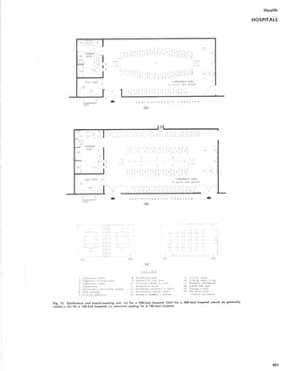
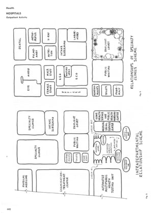
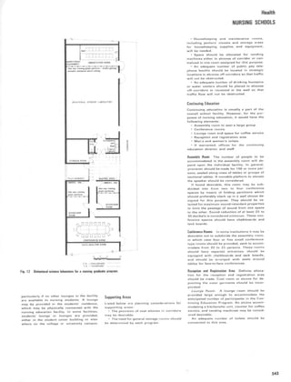
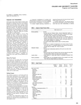
This document provides a table of contents for the book "Time-Saver Standards for Building Types Second Edition". The table of contents lists 11 chapters that cover various building types including residential, educational, cultural, health, religious, governmental, commercial, transportation, industrial, recreation, and miscellaneous structures. Each chapter contains multiple building program types with relevant dimensions, spaces, and design considerations. The document also lists contributors to the book.


![Residential
HOUSING FOR THE ELDERLY
7. Wall-mounted hanging devices for cooking
utensils such as pots, pans, large spoons,
etc., should be provided at convenient loca-
tions.
PERSONAL HYGIENE EQUIPMENT
The following requirements are the minimum
equipment specifications for elderly develop-
ments; they are also applicable for adoption for
use by the handicapped. Each requirement is ac-
companied by locational and size parameters.
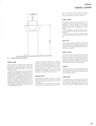
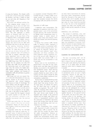
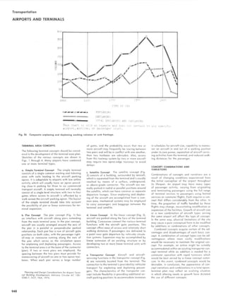
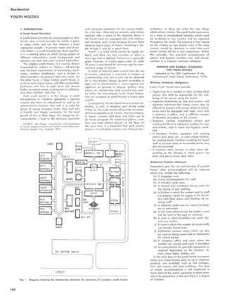
The Lavatory Basin Each bathroom or lavatory
shall have a lavatory basin firmly supported to
withstand pulling or leaning loads of up to 300
pounds. Vanity cabinets are not recommended
as they require excessive stooping and leaning
to be used . Vanity counter tops are desirable.
Provision for storage should be made in wall-hung
cabinetry where necessary.
Basins should be of the cantilever type, either
wall-mounted on chair hangers or mounted in a
vanity top. An installation of this kind is more
easily used by someone in a wheelchair. The most
desirable mounting height for basins will provide
a minimum clear dimension below the basin and/
or vanity top of 2 feet and 2 inches and place
the top of the basin and/or counter 2 feet and
9 inches above the floor. Water taps on basins
should be low profile with cross shaped or lever
handles. Round knobs should not be used. (See
Fig. 30a.)
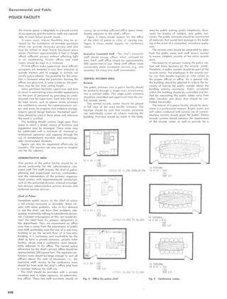
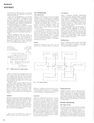
The Water Closet Each bathroom or lavatory
shall have a water closet with a seat height of
17 inches (the elderly have difficulty with seating
and standing motions) . If users in wheelchairs are
anticipated, the seat height should be 20 inches .
Where economically feasible, the water closet
should be of the wall-hung type for convenience
in floor cleaning . (See Fig. 30b.) The toilet-paper
holder should be located in front of or directly
at the side of the water closet, in a position where
leaning or twisting is not required to use it.
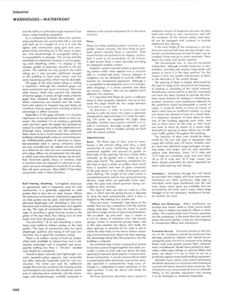
Bath and Shower The question of whether a
bathtub or shower is more desirable has been
debated at length. It has been fairly well estab-
lished that showers are both cleaner and safer
than bathtubs, and showers seem to better meet
the goal of extending the span of independent
living for the elderly. Many elderly persons, how-
ever, enjoy and need the therapeutic benefits of
a sitz bath. The situation could easily be resolved
by providing both a shower and a bathtub in
separate installations; however, this is not eco-
nomically feasible . It seems, therefore, that a com-
promise is required, that is, a specially manufac-
tured tub/shower combination. This compromise
is the recommended solution, although showers
will be considered where central bathtubs are
provided on each occupied floor (one tub for
twenty dwelling units).
Bathtubs should have controls that are easily
operated from outside of the tub without exces-
sive leaning or stretching and should include an
automatic mixing valve with an upper tempera-
ture limit of 120 degrees F. Tubs shall have a
flat bottom with a non-slip surface. Abrasive
tapes and heavy, sharp textures should be
avoided. The sides of the bathtub should not be
higher than 15 inches and the lengthwise dimen-
sion should not be less than 60 inches .
Where showers are provided instead of bath-
tubs (that is, where centralized bathtubs are avail-
able), they shall be of sufficient size to allow
the bather to stand or sit outside of the area
of the spray while soaping his (her] body. The
shower enclosure should be equipped with a fold-
ing seat as sitting showers prolong independence
for those who either require assistance in standing
or who are completely infirm . As mentioned
above, the shower head should be variable in
height and preferably of the detachable type with
a flexible head. The highest shower head position
should not exceed 60 inches .
Shower controls should be easily reachable
from outside the shower stall and should include
both an automatic mixing valve limiting the maxi-
mum water temperature at the head to 120 de-
grees F., and a water temperature testing spout
to be used by the bather before entering the
shower. The soap dish and grab bar should be
conveniently located 51 inches above the floor
of the shower. Where technically feasible, the
raised entrance curb should be eliminated . If glass
is used in the shower enclosure, it shall be tem-
pered for safety .
Soap dishes and similar attachments should
be recessed . Water controls should be placed so
that they are not a hazard either in normal usage
or when the bather slips.
Bathtubs shall be equipped with shower heads.
The shower head should be adjustable in height
and, preferably, detachable with a flexible head.
There should be several wall positions for the
head to fix it at various heights. Bathtubs shall
be equipped with a detachable seat which allows
the bather to shower sitting down. A grab bar
and soap dish, placed at a high level about 51
inches from the bottom of the tub will avoid the
necessity to bend down for soap or to use the
shower curtain for support when taking a shower.
Glass enclosures instead of shower curtains are
not advisable as they further restrict getting in
and out of the tub.
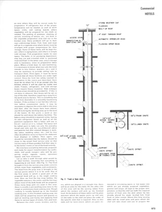
Grab Bars Grab bars are generally overused
and sometimes bear little relationship to the anat-
omy of the human body. If improperly located,
they not only fail to serve the user but they can
also become a hazard if someone should slip.
Grab bars should be used judiciously and wher-
ever possible located to serve more than one bath-
room position . Bars should be approximately 1
inch in diameter, be capable of withstanding a
pulling or hanging load of 300 pounds, and be
fixed to structure members rather than to wall
finishes or materials. There should be at least
one grab bar at the water closet and another
in the bathtub or shower, located and in the con-
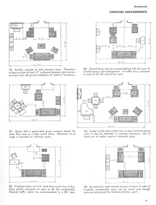
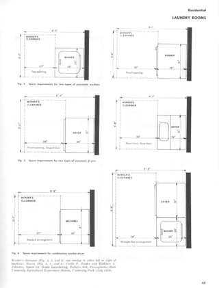
figuration shown in Fig. 31 .
Storage and Mirror The preferred provision for
storage needs is a large mirror behind the lavatory
(not a medicine cabinet/mirror combination) and
a separate storage unit, built into a wall, large
enough to hold both medicine/toiletries and tow-
els. The storage unit should be located so that
reaching across counter tops is not required . If
towel storage is located externally in a linen
closet, the bathroom shall have a mirror behind
the lavatory and a separate medicine cabinet
which is convenient to the lavatory but placed
so that excessive reaching is not required .
Electric Outlets A convenient duplex outlet shall
be located adjacent to the mirror and lavatory
approximately 6 inches above the height of the
lavatory and positioned so that reaching across
the lavatory or counter top is not required.
101
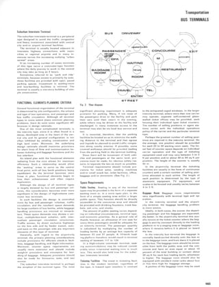
Fig. 30 Fig. 31 Bath and shower.](https://image.slidesharecdn.com/timesaverbuildingtypesnew-220410120843/85/Time_Saver_building_types_new-pdf-120-320.jpg)
![Residential
HOUSING FOR THE HANDICAPPED
THE NEIGHBORHOOD
Accessibility to community services and
facilities is the first factor to consider in site
selection.
Primary services and facilities are: employ-
ment opportunities; clinics; vocational reha-
bilitation programs ; inexpensive private and
public recreation (such as movies, parks
lively with activities for participation and
view, libraries, etc.); churches ; stores includ-
ing drug, grocery and variety; barber and
beauty shops; inexpensive restaurants;
schools.
Another important factor is accessibility to
public transportation . To the employed im-
paired citizen, as well as to staff and visitors,
good public transportation may be a necessity.
To the unemployed, good transportation may
keep him in touch with the world, participating
in meaningful and dignified activities . Eco-
nomical public transportation with a nearby
stop, without intervening hazards, is highly
desirable. Such transportation may be either
existing or assured by the time the develop-
ment is first occupied .
A convenient location is so essential for
impaired persons that it may outweigh the
other standards and criteria for evaluating resi-
dential neighborhoods. Neighborhoods close to
specialized services, such as sheltered work-
shops, should be considered if the neighbor-
hood also possesses the other more generally
used services and facilities . It is easier and
less expensive to arrange transportation for a
particular group of tenants using a single
facility than to bring the multiple, less spe-
cialized, but equally essential public and private
facilities and services within reach of all
tenants.
Urban renewal areas, which contemplate
commercial shopping centers and other ad-
juncts to housing needs, may furnish desirable
sites.
THE SITE
The criteria for selecting residential sites in
general should apply. [These criteria cover
economy, topography, subsoil conditions, and
existing utility services . Sites subject to in-
dustrial smoke, traffic hazards, excessive
noise, or polluted air should be avoided .]
The site should allow for development so
that structures can be oriented to give resi-
dents the advantages of local climate.
Odd or irregularly shaped sites should be
carefully evaluated based on amount of usable
land and cost of its maintenance.
If the community has restrictive ordinances,
zoning, or other local controls which would
adversely affect the proposed development in
a particularly good location and site, waivers
should be investigated . In applying for such
waivers, it is important to remember that the
housing is to be residential, designed for in-
Housing for the Physically Impaired, Depart-
ment of Housing and Urban Development,
Washington, D .C ., 1968 .
dependent living . It is neither an institution
nor a nursing home .
An important special consideration is slope
of the site . For the physically impaired, a
comparatively flat site is needed . Steeper and
more rugged sites may be used but with doubt-
ful success. Such sites should be evaluated in
terms of the costs of any special improvements
required to serve the limitations and needs
of the tenants. Examples of such extra costs
would be those for constructing retaining
walls to create useful flat outdoor sitting and
resting areas or constructing gently sloping
pedestrian ramps throughout the site . Extra
maintenance costs (upkeep of banks, lawn
areas, and in some climates snow removal,
etc.) may result in increased rents.
It is important to have outlooks, both natural
and created, that provide interest or beauty
and contribute to pleasant living . Many ten-
ants will undoubtedly spend more time at home
than would a comparable group of nonimpaired
individuals. Views of such things as wooded
areas, hills, night-lights, and distant traffic ;
of planes, boats, trains and automobiles are
desirable, and count as positive factors in
site selection .
Consideration should be given to the exist-
ing and proposed approaches to the site (street
improvement, widening ; surface; sidewalks)
and public utilities .
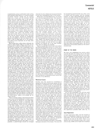
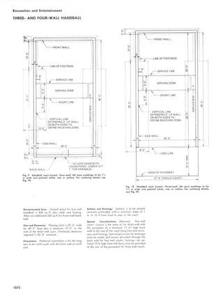
ACCESS, RAMPS, PEDESTRIAN WALKS
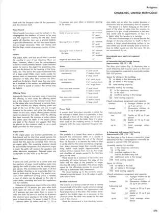
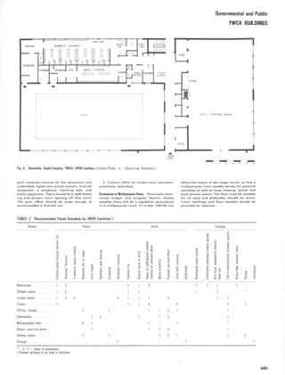
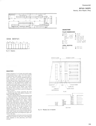
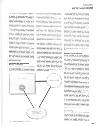
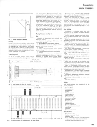
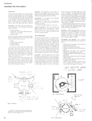
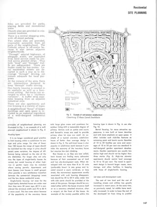
Access All building entrances to be used by
the tenants should be approached by paved
walks, with nonskid surface, sloped for drain-
age, but not over 1 in 20 (or 5 percent) . Steps
should not be used.
Landing platforms at all building entrance
doors should be level, sloped only as required
for drainage. The platform width should be at
least 1 ft beyond the door jambs. Platforms
should be at least 3 ft deep if doors swing in,
and 5 ft deep if doors swing out, but never less
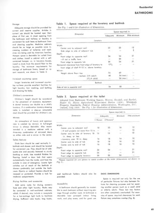
than 3 ft beyond the edge of the fully open door.
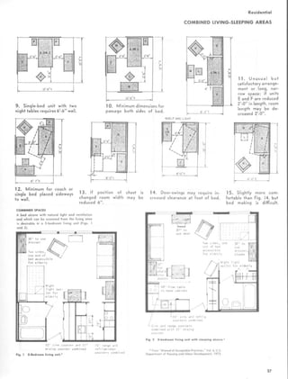
(See Fig. 1 .)
Ramps Most wheelchair users can negotiate
a ramp sloped 5 percent or less without assis-
tance. Steeper ramps limit independent chair
use and should never be used. They are hazard-
ous not only to wheelchair users but also to
persons with artificial limbs and to the elderly.
Ramp surfaces should be fireproof and non-
slip . (See Fig. 2.)
If the vertical height requires two ramps to
achieve the properly graded slope, the ramps
should be no longer than 20 ft, separated by a
level platform at least 5 ft-6 in. long, to pro-
vide ample rest space. Such two-run ramps may
be in a straight line ; however, a more desirable
and safer arrangement would be a 90 or 180 °
turn at the platform.
When more than two ramp lengths are re-
quired, the descent should be broken by turns
to be negotiated on level platforms.
The recommended width for a one-way ramp
is 3 ft between handrails. At least 6 ft should
be provided for two-way circulation.
Handrails and anchors should support 250
Ib for 5 min; they should extend at least 12 in.
(24 in. is preferable) beyond the beginning and
end of the ramp to assist persons with poor
vision, and they should be returned to a wall
or an upright post for safety .
Handrails installed specifically for children
should be at a height of 24 in. Local codes
or special safety objectives might necessitate
the installation of additional, higher rails.
Pedestrian Walks Pedestrian walks at street
curbs should be ramped . The ramp should
not protrude onto the street but be indented
into the curb ; it should have a nonslip surface
colored orange, or curb jambs should be col-
ored to assist those with poor vision . Greater
slopes than 2 in 12 could hinder wheelchair
use.
PARKING
The parking areas should be moderate sized
and conveniently located to provide easy and
safe access to entrances. (See Fig . 3.)
There should be no steps or curbs from the
parking area to the dwelling buildings or to
community space. Space should be planned to
eliminate pedestrian circulation behind parked
vehicles-a particularly hazardous area for the
individual with limited mobility .
A desirable plan for multiple parking space
would extend the parking surface into the
sidewalk, eliminating the need for curbs.
Surface drainage would place the sidewalk
at the high point and the center of the parking
driveway at the low point.
A pipe rail is necessary between the side-
102
Fig. 1 Single-run entrance ramp .
Fig. 2 Street-curb ramp for wheelchair .](https://image.slidesharecdn.com/timesaverbuildingtypesnew-220410120843/85/Time_Saver_building_types_new-pdf-121-320.jpg)


![Residential
HOUSING FOR THE HANDICAPPED
with limited reach and can easily be converted
for convenience of future tenants when it is
initially provided with flexible-tube water sup-
plies and ample length slip-joint tailpiece waste
line . (See Fig. 24.)
The mirror over the lavatory should be us-
able from both standing and sitting positions.
If fixed to the wall, the mirror should be
tilted forward at the top. Bottom-hinged mirror
provided with a friction stay arm is available.
This mirror permits the top to tilt forward to
any distance up to 6 in. and can be installed on
the medicine cabinet door.
The medicine cabinet should be mounted so
as to be accessible from standing or sitting po-
sition, and its location in the bathroom should
be carefully considered . (See Fig. 25.)
The water closet seat of standard height,
15 to 16 in., can be used by ambulant impaired
persons. Forthe semiambulant and others who
find this height difficult, a standard manu-
factured sanitary chair with arm rests and
seat 18 in. high is recommended. The advan-
tage of the chair is twofold; it can also be used
in the shower, and would not be present when
not needed by the occupant . Some wheelchairs
are equipped to be used as toilet chairs . Grab
rails should be provided at the closet . One
manufacturer can supply an integral seat,
cover, and grab bars . (Note: Detachable ring
seats that clip on the china bowl or seat are
unstable and should be avoided .)
Other recommendations are shown in Figs .
26-34.
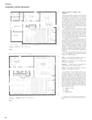
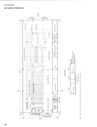
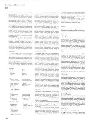
Storage
Adequate storage space should be provided
within the dwelling . Separate units are desir-
able for hanging coats and for bedroom, linen,
and general storage. The storage units may be
closets enclosed by partitions or wood cabi-
nets, fixed or movable, to serve as room di-
viders . Kitchen cabinets are discussed else-
where.
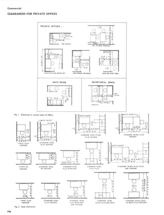
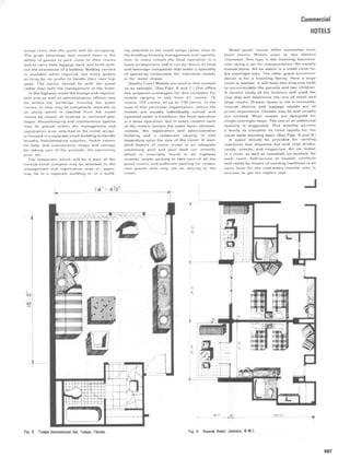
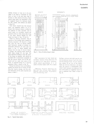
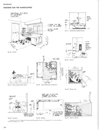
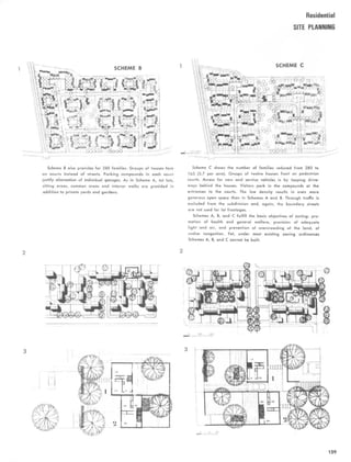
The cost closet should permit the hanging
of clothing from both standing and sitting
positions. For the standing position, the fixed
shelf height at 5 ft-6 in. with the clothes-hang-
ing pole below is standard . For the wheelchair
position, 4 ft to 4 ft-6 in. is most convenient .
The lower shelf and pole unit should be adjust-
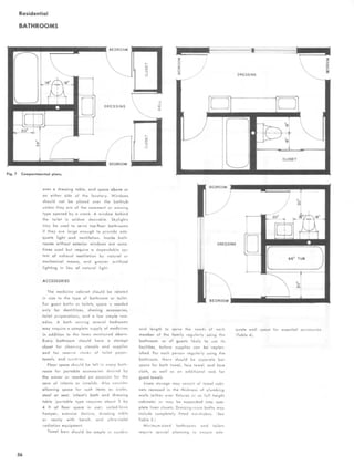
able from 4 ft to 5 ft-6 in . (See Fig. 35.)
For one-person dwellings, the coat closet
shelves and pole should be made adjustable.
For larger dwellings, both the standing posi-
tion height and the adjustable wheelchair
height should be provided by dividing the
closet with a wood partition. (See Figs . 36
and 37.)
The bedroom clothes closet should be di-
vided by wood partitions into two sections, one
with shelves and pole for the standing position
height and the other adjustable for the wheel-
chair user.
The linen closet shelves should be adjustable
in height, from the baseboard up. Persons in a
sitting position can easily reach low shelves,
but low shelves are difficult for those on
crutches. The linen closet often stores items
other than linen, such as clothes hamper, bath-
room supplies, etc. Adjustable shelves provide
the needed flexibility.
A storage unit should be provided for storing
supplies and cleaning equipment, ironing
board, canned goods, etc . The unit need not be
in the kitchen, but it should be easily acces-
sible from the kitchen . It may be a standard
prefabricated cabinet resting on the floor or a
built-in closet .
A general storage area and kitchen storage
space may be combined if located conveniently
to the kitchen .
Although the general storage area is not
primarily designed for the storage of excess
furniture, it should be large enough to store
foot lockers, suitcases, vacuum cleaner, large
and seldom-used cooking utensils, work
clothes and work shoes, and-in large family
units, folded baby furniture and unused toys .
Increasing the amount of storage space does
not always economically resolve the storage
problem . The best use of available space can be
made by careful arrangement of varying shelf
widths adjustable for height and use of hook
strips for hanging such items as brooms, mops,
vacuum cleaner hose, etc.
Windows
The following hazards should be avoided when
selecting and installing windows: windows that
project, outside or inside, beyond the wall line
and protrude in the path of persons walking ;
windows that require climbing or leaning out to
clean; windowsills too low to provide adequate
safety from falling or high sills which block the
view from a sitting or bed position . The recom-
mended windowsill height is 28 to 32 in . ; [it
can be at floor level if the window opens on a
terrace or balcony] .
Windows should be easy to operate, lock,
and clean. Operating and locking hardware
should be located for convenient reach from
a sitting or a standing position and be of the
type easily grasped by arthritic or otherwise
impaired hands.
Window types deserving consideration are :
- The modified double-hung window which,
in addition to sliding up and down, permits
each sash to pivot and swing inward for clean-
ing with no interference by insect screens or
storm panels when used, or curtains, shades,
and venetian blinds .
The awning type with push bar or rotary
gear operator set below the screen (some of
these windows require the screen unit to be
removed to clean the window, others permit
the swing panels to reverse when fully opened
for cleaning the outside glass surface) . Clean-
ing of upper glass may be difficult for some .
The hopper type, somewhat similar to the
awning type except that window units open in-
ward and screen is on the outside. This type
window may interfere with draperies and
shades and may project inward to the point of
being a hazard .
Horizontal sliding windows. Cleaning of
upper glass may be difficult for some .
Aluminum windows coated by the manu-
facturer for protection during shipping and
installation have some advantage over win
dows requiring maintenance painting .
Window items which increase maintenance
costs should be avoided. Dissimilar metals
that cause galvanic corrosive action in the
presence of moisture should not be used. The
best rust prevention for steel is hot-dip gal-
vanizing. To prevent condensation and early
ill
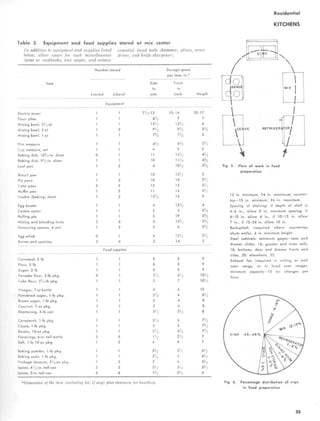
Fig. 35 Two-person bedroom closet . Coat closet
same but smaller.
Fig. 37 Closets. Source: Handbook for Design : Spe-
cially Adapted Housing, VA Pamphlet 26-13, Veterans
Administration, Washington, D.C., 1978 .](https://image.slidesharecdn.com/timesaverbuildingtypesnew-220410120843/85/Time_Saver_building_types_new-pdf-130-320.jpg)


![Residential
HOUSING FOR THE HANDICAPPED
foot-candles attable height. Supplemental mov-
able lights (floor and table lamps in the
lounge and library) should be provided at
required utilitarian locations for decorative
and functional use. Avoid creating hazards
by exposed extension cords to floor and table
lamps.
There should be no hazards within the com-
munity space, such as thresholds, freestanding
columns, pilasters, projecting radiators, or
drinking fountains.
Air conditioning of all community space
used by physically impaired or elderly should
be considered .
Lounge
When combined with the entrance lobby of
a community building or the elevator lobby
of a multistory structure, a lounge provides
increased activity and interest . The elderly and
the impaired enjoy watching the going and
coming tenants and visitors . In cold climates
a vestibule entrance is necessary.
Locating the mail delivery room in the ele-
vator lobby near the lounge is recommended.
The décor of the lounge should be coordi-
nated-wall colors, white ceiling, accent colors
-in draperies, furniture, lamps, and plastic or
cloth upholstery materials. Woven cloth up-
holstery material used in the lounge must be
stainproof.
Selection of chairs and sofas for the physi-
cally impaired, especially the semiambulant,
deserves special consideration. Seat height 18
in. above floor is best. Sturdy arm rests help
the impaired to rise . Chairs should not over-
balance when weight is applied on the arm
rest . Deep seats (over 20 in .) are undesirable.
Semistiff, upholstered furniture is recom-
mended.
matic defrosting food compartment is recom. and shelves that can be adjusted. Some drawer-
mended. In large kitchens, consider how best type storage space may be desirable. Apronless
to provide cold drinking water. tables are recommended.
A kitchen service entrance should be planned Special consideration should be given to
to accommodate delivery of supplies, catering providing outlets for both 110 and 220 volts
service, and garbage and trash removal. A in craft activity area-consult with operating
garbage grinder may be installed in this kitchen staff.
-the continuous-feed type is recommended.
Floor and wall surfaces should be of easily Library
cleaned materials and finishes . Well cabinets
should have adjustable shelves . At least one The larger community spaces may provide,
closet, with lock, for storage of staple supplies if need is established, an area for a branch of
should be provided, as well as a cabinet for the city library, which will furnish book stacks.
mops, brooms, and cleaning materials . When the book stacks can be locked or other-
wise segregated from the rest of the library,
Craft Activity Area then the area generally used for reading could
on occasion be used for small gatherings or
The space for craft activities should have other uses-again, flexibility. If possible, this
maximum flexibility for varied arrangement. space should be large enough for apronless
Fixed partitioning of cubicles is not desirable- tables and for chairs . Since smaller projects
no flexibility. It is best to concentrate the craft seldom can afford a separate library, the lounge
space in one room, dividing the space with may be provided with adjustable shelves
movable (on casters with step-on brakes) for books and periodicals . This same idea,
wood storage cabinets for materials and sup- while less desirable than a separate library,
plies. This provides for multiple use of space may be considered for large projects,
and permits adapting space size to tenant in-
terest and various activities .
Health Clinic
The movable divider cabinets should not
extend to the ceiling. A height of about 4 ft A clinic can contribute substantially to the
provides views Ito the person who is] standing welfare end continued independence of the
and improves ventilation and distribution of elderly and physically impaired. Clinic space
light ; further, no change in the prearranged may be provided when such facilities are not
distribution of air conditioning is required . available near the site .
The cabinet units should be of sizes easy to In small developments, the permissible clinic
move . Standardized units are advisable, but space may consist of an office and examination
they should be selected or designed for the room for use of doctors and nurses who visit
materials and supplies to be stored. It is also during scheduled periods.
advisable to have cabinets that can be locked In larger developments, space for a variety
Recreation or Multipurpose Room
This space may be subdivided by sliding or
folding soundproof dividers or doors-the
ceiling should be acoustically treated. The
space should be suited for meetings, movies,
concerts, plays, lunches, etc. Because of the
nature of such activities, convenient storage
space for tables and other items should be
provided. An inventory of the items is needed
to adequately plan an orderly and functional
storage-flexibility of use with adjustable
shelves is desirable.
Building codes may require emergency exits,
but at least one exit door may be desirable for
departing guests after evening affairs.
Structural columns or other obstructions
within this space should be avoided or elimi-
nated if possible in order that the space may
function as one room for certain occasions.
Tables without aprons, which will permit
wheelchair arms to fit underneath, are recom-
mended-they also take less space to store.
Kitchen
A kitchen should be provided adjacent to the
recreation room . Equipment and arrangement
should facilitate efficient and functional food
preparation and clean-up . The kitchen may be
used by the tenants.
The kitchen should be planned and designed
to be useful in demonstrating and instructing
on food preparation, in planning balanced
diets, and in conducting various consumer
education activities . For this purpose, the divi-
sion between the recreation room and kitchen
should be a sliding or folding divider or doors
which can be locked or secured.
A two-door refrigerator freezer with auto-
11 4
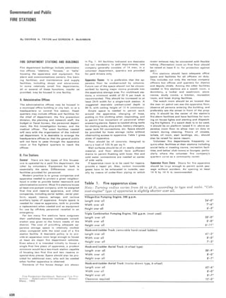
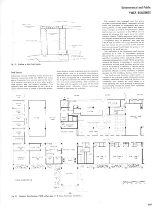
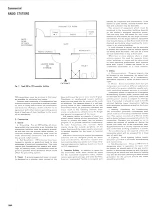
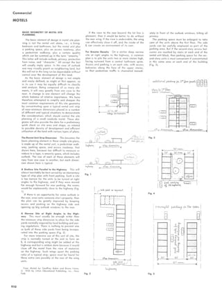
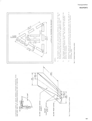
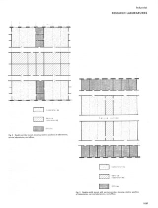
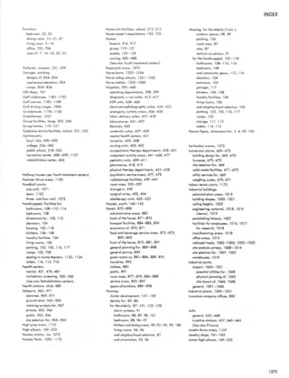
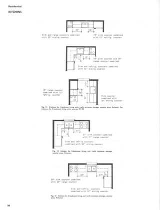
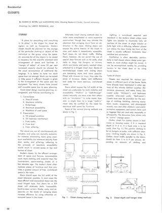
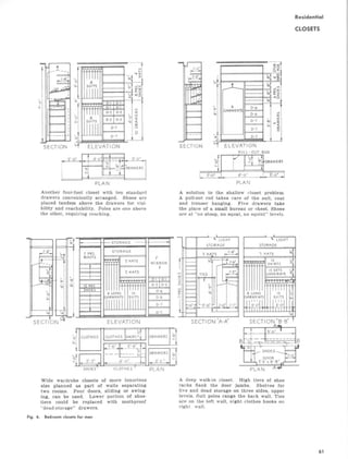
Fig. 43 Toilet stall. (a) Plan . (b) Elevation. (c) Isometric. Source: An Illustrated Handbook of the Handicapped
Section of the North Carolina State Building Code, Raleigh, 1977.](https://image.slidesharecdn.com/timesaverbuildingtypesnew-220410120843/85/Time_Saver_building_types_new-pdf-133-320.jpg)
![Residential
HOUSING FOR THE HANDICAPPED
of health services may be provided, including
physical therapy and hydrotherapy, a special
need of the physically impaired . Occupational
therapy may be conducted in the craft activity
area . This type of clinic would generally be
active each work day and should have a wait-
ing room with a separate outside entrance per-
mitting nontenant patients to come and go
without traversing the lobby or lounge .
Washrooms
Separate washrooms for each sex should be
provided in community space . At least one
water closet compartment for the semiambu-
lant and wheelchair user should be provided in
each washroom in addition to other plumbing
fixtures .
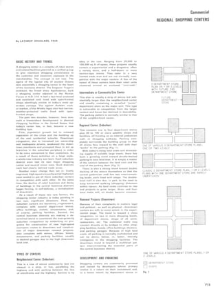
Urinals in the men's room should be of the
wall-mounted type, also for sanitary reasons .
The front lip of the urinal should be 18 to 19 in .
above the floor, which is convenient for per-
sons in wheelchairs as well as others . (See
Fig . 45 .)
The installation of lavatory and wall mirrors
is discussed in the section on Dwelling Units,
under Bathroom .
A separate staff washroom which can be
used by both sexes should be provided in the
clinic-two washrooms in the large clinic .
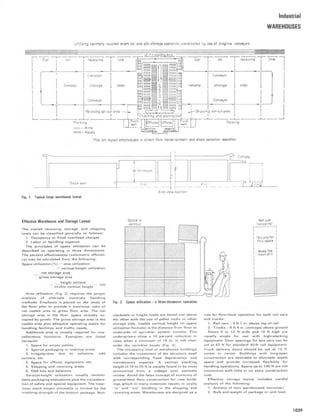
Public Telephones, Drinking Fountains,
Vending Machines
Public Telephones The standard public tele-
phone booth is not usable for most physically
impaired people .
To assist persons with hearing disabilities,
telephone receivers should have adjustable
amplifiers .
on the standard fixture . Persons in wheelchairs
can use a children's drinking fountain 31 in .
high . Pushbutton control is best for persons
with impaired hands . Some drinking fountains
are available with both hand and foot control .
(See Figs . 46 and 47.)
Drinking fountains with paper cup dis-
pensers should have the dispensing mech-
anism 30 to 34 in . above the floor . Drinking
fountains resting on the floor and projecting
into the corridor are a hazard ; recessing into
wall pockets makes floor cleaning difficult .
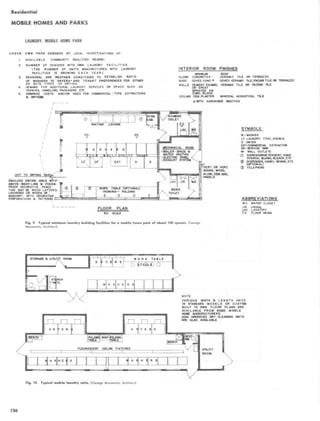
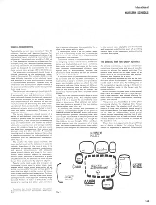
The washrooms should be located to permit
convenient use by outside visitors to the clinic
and tenants using the various activity areas .
The toilet stall illustrated in Fig . 43 is a pos-
sible solution for persons using wheelchairs .
Maximum maneuverability for persons using
crutches or wheelchairs is provided in toilet
stalls, with the toilet fixture set toward either
side wall .
Horizontal grab bars should be installed on
the side and rear wall of the water closet com-
partment . Such bars (1 'h-in . outside diameter)
should beat least 4 in . from the wall to prevent
pinioning the wrist, hand, or arm in case of
a fall . Grab bars should support 250 lb .
The water closet seat should be 18 in . above
the floor. A wall-hung closet is most suitable
forthe semiambulant person-it also makes for
ease of floor cleaning and sanitation . (See
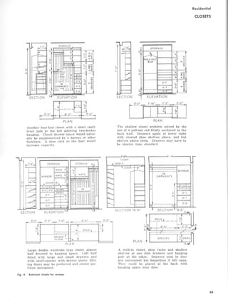
Fig . 44 .)
S
Fig . 46 Semirecessed model with projecting basin
is recommended because the wheelchair approach
is parallel to the wall . A frontal approach is difficult .
Two units may be connected to one water chiller .
The second unit should be set 40 to 42 in . above
the floor and S to 6 ft from the other. The water
stream rises about 4 in . above the bubbler orifice .
The pushbutton-dial receiver is more desir-
able for the impaired than the rotating dial .
The standard coin-box receiver mounted
above the table or shelf elevates the coin slot
4 ft above the floor, which is not convenient
for some with physical impairments . A desk-
type telephone, resting on a table or shelf
about 31 in . above the floor, is the most con-
venient (bottom of shelf must clear wheelchair
arm rests) . For wheelchair users, the desirable
height for coin slots is about 3 ft above the
floor or 6 in . above the counter top . The local
telephone company should be consulted for
advice regarding available special and standard
equipment which is especially desirable for the
physically unpaired .
Drinking Fountains The standard adult drinking
fountain is satisfactory to all except wheel-
chair users . For wheelchair users, the fountain
bubbler should be 31 to 33 in . above the floor .
Two-level drinking fountains that satisfy both
standard and wheelchair height requirements
are available, or a low-level unit can be added
Fig. 47 The floor cabinet model is available with
an additive basin ; while this two-level unit would
serve the dual use, it is not recommended because
of the hazard created to persons with poor vision
and to blind persons who will be using the wall
handrail.
Vending Machines The need for and location
(not in prominent view) of vending machines
which dispense soft drinks, etc . should be con-
sidered .
Other Areas
The minimum corridor width should be 6 ft .
Grab rails should be provided on each side
wall . (See chapter on dwelling structures for
special assistance to those with poor vision .)
The minimum door width should be 3 ft . Doors
from the corridor to the various rooms, when
fully open, should not extend into the corri-
dor . They are a hazard, especially to persons
with poor vision .
Consideration should be given to the need
for a staff management office . In multistory
buildings, such an office should be located to
provide an unobtrusive view of the lobby
entrance and elevators .
Office space in which tenants may, in pri-
vacy, discuss problems with counselors and
[which may also serve] for other uses should
be considered .
Consideration also should be given to tem-
porary coat and umbrella storage facilities
for tenants and visitors using the recreation or
multipurpose rooms . This facility is best lo-
cated where it can be visually supervised .
Closed cloakrooms should be avoided .
Certain rooms and storage areas will require
locked doors .
11 5
Fig . 45 Wall-hung urinal.
Fig . 44 Wall-hung toilet-desirable .](https://image.slidesharecdn.com/timesaverbuildingtypesnew-220410120843/85/Time_Saver_building_types_new-pdf-134-320.jpg)

![Residential
PARKING FOR THE HANDICAPPED
1 . Parking spaces of greater width than normal
are necessary for people who are disabled
and use mechanical aids such as wheelchairs,
crutches, and walkers. For example, persons
who are chairbound must have wider aisles
in which to set up their wheelchairs.
2. A minimum of two spaces per parking lot
should be designed for use by physically re-
stricted people, or at least one space per 20
cars, whichever is greater.
3. These spaces should - be placed as close as
possible to a major entrance of a building
or function, preferably no more than 100'-0
away.
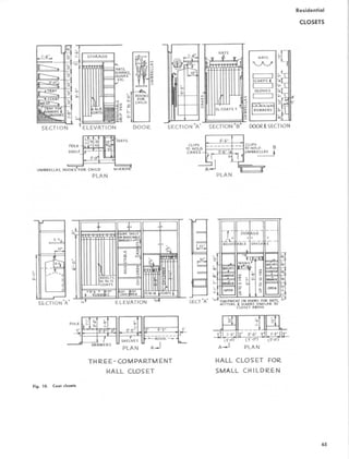
4. Parking patterns are described in 5 and 6 be-
low (Fig . 51).
5. Parallel Parking:
Parallel parking spaces should be placed adja-
cent to a walk system so that access from
the car to the destination is over a hard sur-
face . Such spaces should be made 12'-0
wide, 24'-0 long and should either have a
1 :6 ramp up to the walk, or should be sepa-
rated from it by bollards or some other device
if the road level is at the same elevation as
the walk. These areas should be designated
as special parking since they may otherwise
appear to be a drop-off zone.
6. 90 Degree and Angled Parking:
a. Spaces designed for use by disabled peo-
ple functioning with large mechanical aids
as described above, should be 9'-0 wide
as a minimum. In addition to the 9'-0, a
3'-6 to 4'-0 wide aisle between cars
should be provided for access alongside
the vehicle (Figs. 49 and 54). It is important
that there be plenty of room to open the
car door entirely, and in the case of a de-
pendent chairbound person, that there be
room for friends or attendants to assist him
[or her] out of the car, into his [or her]
chair, and away from the car.
b. The 9'-0 wide standard space width for
a parking stall, with no aisle between
spaces, does not drastically hinder semiam-
bulant people with minor impairments, but
an 8'-0 width, unless used exclusively for
attendant parking, is too narrow and
should be avoided.
c. A 4'-0 minimum clear aisle width should
be provided between rows of cars parked
end to end. The overhang of the automo-
bile should be taken into account so that
the island strip is wide enough to leave
a 4'-0 clear aisle when the stalls are filled.
A strip 8'-0 wide is a recommended mini-
mum for an on-grade aisle, and 10'-0 is
a recommended minimum where the aisle
is raised 6 above the parking level.
d. If the aisle between rows of cars is not
at the same grade level as the cars, then
ramps must be provided to mount the curbs.
A 1 :6 (17%) ramp is suitable for such a
short distance .
e. Economically, the installation of an on-
grade 4'-0 wide pathway is less expensive
than a raised walk. Precast car stops to
delineate the passage can be used provid-
ing that a 4'-0 wide space between the
ends of stops is maintained to allow access
to the main passageway .
11 7
Fig. 51 Parking patterns .](https://image.slidesharecdn.com/timesaverbuildingtypesnew-220410120843/85/Time_Saver_building_types_new-pdf-136-320.jpg)

![Residential
GROUP HOMES
SPATIAL REQUIREMENTS
Building : Approximately 6,650 square feet for
a 12-person home and 7,400 square feet for a
16-person home are allotted . This area includes
space for the garage and basements. The building
can be arranged on one level or on two full or
partial levels .
Entry
Major This spatial requirement varies according
to the inclusion or exclusion of the vertical
circulation element within the space. Normally,
an area of approximately 90 square feet should
be sufficient. A closet with a minimum of 6 linear
feet of hanging space should be adequate .
Minor The size of this space varies; however,
it should be adequately sized for ease of
circulation through it.
Living Space
This space varies in size . In a typical 16-resident
group home it is approximately 400 to 500 square
feet .
Recreation Room
This space varies in size . In a typical 16-resident
group home it is approximately 400 to 500 square
feet and as previously indicated should be sized
to seat all residents. It is required that direct
access suitable for use by the physically handi-
capped be provided from the main living area
and to the common outdoor activity area .
Kitchen
The area designated for food preparation shall
meet all of the requirements of the Michigan
Department of Public Health, Michigan Depart-
ment of Social Services, and the applicable por-
tion of the F.H .A. Minimum Property Standards
for Multifamily Housing. The typical kitchen is
equipped with the following appliances :
refrigerator
freezer
commercial dishwasher
cooktop range with exhaust hood
double oven
disposal
Dining
The dining space shall have a glazed area of
at least 10 percent of the floor area. The following
clearances and sizes will be assumed for design
purposes :
2'0 for table edge for each diner
3'0 minimum table width for tables seating
four to six persons
3'3 for larger tables
4'0 minimum clearance between the table
edge and obstruction where seating and cir-
culation occurs
3'0 for circulation clearance
2'6 for seating clearance table to obstruction
Clearances are shown in Fig. 1
Powder Room
This space should be sized to accommodate physi-
cally handicapped residents. A water closet and
Special Group Housing for Adults Development Pro-
cess, Michigan State Housing Development Authority,
Lansing, Michigan, 1978 .
a lavatory without vanity base should be pro- Specially designed desks/storage units may
vided. be used.
Minimum clearance shall be maintained as fol-
Bedroom lows :
No resident room shall accommodate more than
1'6 between wall and the side of bed that
three persons. Each occupant of a room shall be is least used
provided with a separate storage closet of at
3'0 in front of dresser
least the following:
3'6 diameter area for dressing
. 4'0 x 2'2 clear and an opening width of 2'6 for access to and use of table as a desk
at least 3' clear. 3'0 door opening
. The closet shall be equipped with a shelf 2'6 general circulation
and hanging rod.
Th
. The bedroom shall be equipped with windows
e bedroom shall be designed to provide a
hose glazed area is at least 15 percent
clearly defined area within the room for each
w
f the floor area of the room.
occupant. It is preferable if one occupant does
o
. Windows shall be operable and have a free
not have to violate the area of another in order
air ventilation area equal to half the glazed to get to or from the room entrance or [sic] the
bedroom.
area.
If possible, the room should be designed so
. Resident bedrooms shall accommodate at
that there is a visual separation between the
least the following:
sleeping areas. Generally, resident rooms should
2 beds: 3'3 x 6'6 min . be grouped together and served from common
2 dressers : 3'0 x l'6 min. halls or foyers . These halls shall provide direct
1 lounge chair: 1'10 x 1'10 min. access to shared facilities for the residents without
2 bedside tables : l'0 x l'0 the necessity of going out of doors. The room
119
Fig. 1 Clearances for central dining.](https://image.slidesharecdn.com/timesaverbuildingtypesnew-220410120843/85/Time_Saver_building_types_new-pdf-138-320.jpg)


![Educational
COLLEGE AND UNIVERSITY FACILITIES
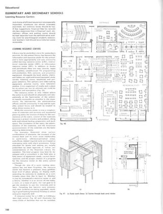
Lecture Rooms
full width of the room, on which the teacher may
walk the length of the board without danger of
falling off the end. The chalkboard should then
be raised correspondingly higher above the class-
room floor for better visibility . The mathematics
teacher needs a table on which he [she] can place
his [her] lecture notes and papers, but it is better
to have this table either movable on casters or
fixed at the side of the platform where it does
not block the view of the chalkboard from the
first two rows of students . If an overhead projector
is to be used, there must either be a place where
it can be mounted permanently at the front of
the room, or there must be provision for rolling
it in on a cart and connecting it electrically. In
the latter case, the front platform might be slightly
lower and be accessible by a ramp. The mathe-
matics teacher seldom sits during a lecture but
may wish to sit down during an examination.
There should be a chair by his [her] table or desk .
A lecture room should be so placed in a building
that it is accessible to students without overcrowd-
ing of corridors or stairways. Coat racks, ade-
quate bulletin boards lining the corridors, and
ample toilet facilities should be provided nearby.
The room itself should be arranged so that the
audience can see well, hear well, and be comfort-
able . In part this depends on temperature, humid-
ity, background of light and sound, and seating
space.
Projection Systems The large lecture room should
be built to accommodate a variety of projection
systems that may be used immediately or in the
more distant future . An overhead projector re-
quires an electrical outlet near the lecturer's table,
placed so that the lecturer will not trip over the
cord, and also a screen properly mounted to as-
sure that the entire class has good visibility with
minimum distortion . More screens or a wide screen
may be needed to enable the lecturer to use two
or more overhead projectors at once. If movies,
films, or slides are projected from the rear of
the room and reflected from a front screen, the
room should have a projection booth, or at least
a suitable stand and electrical outlet for the pro-
jector . Remote controls for operating the projector
are desirable. Shades may be required for dark-
ening a room with windows. If the rear screen
method of projection is to be used, in which the
image is thrown onto a translucent screen
mounted in the front wall from a projector in
an adjacent room beyond the front wall, the build-
ing plans must include adequate provision for
this projection room.
A room or space for the preparation of tran-
sparencies or other visuals is a corollary of their
use. Material can be prepared on ordinary paper
and copied quickly onto a transparency by a ther-
mal duplicator or similar equipment. Such copies
can be posted after the lecture for inspection
by students . Storage for such materials must also
be provided, as well as for any materials distrib-
uted to students to supplement their lecture notes.
Provision for receiving and transmitting televi-
sion is also an important consideration in planning
a lecture room for large group instruction.
Seating and Visibility Good visibility depends
not only on the arrangement of chalkboards and
of projection screens and equipment, but also
to a large degree upon seating arrangements.
Factors to be considered are avoidance of ob-
J. Sutherland and John W. McLeod, Buildings and
Facilities for the Mathematical Sciences, Conference
Board of Mathematical Sciences, Washington, 1963 . Fig. 4 Optimum viewing angles.
Fig. 3 A classroom divisible into two seminar rooms.](https://image.slidesharecdn.com/timesaverbuildingtypesnew-220410120843/85/Time_Saver_building_types_new-pdf-253-320.jpg)


![Fig. 2 Fig. 4
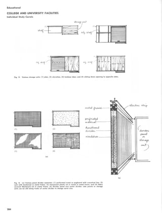
RESIDENCE HALLS
Sleeping and Study Quarters (Fig. 1)
Space There must be a minimum clear floor
space in such areas of 6' [183 cm] by 6' [183
cm] enabling a 360° turn by a wheelchair.
Working Area Space clearance under counter,
table, and desk tops to be used by a wheelchair
student shall be a minimum of 271/2 [69.8 cm]
in height and 32 [81 .3 cm] in width.
Beds Beds shall have minimum dimensions of
3' [92 cm] by 6' [183 cm] and between 19 [48.3
cm] and 22 [55.9 cm] in mattress height from
floor level.
Mirrors Mirrors should be adjustably hung (a
minimum of 2'-0 [61 .0 cm] in length) so that
the bottom is 30 [76.2 cm] above floor level.
Where this lower height is not feasible, mirrors
of greater height shall be tilted from the top to
a degree to sufficiently accommodate individuals
described in rational.
Electrical Outlets Electrical outlets shall be
mounted no lower than 20 [50.8 cm] above floor
level.
Handles and Switches Protruding desk and
dresser drawer handles shall be installed.
Switches for electrical fixtures and equipment
shall be of a toggle or push-button type or
equipped with pull-chains of a minimum length
of 15 [38 cm].
Closets Where one closet is provided for each
occupant, the clothes bar should provide two
different heights. Three-quarters of the total
length should be at 52 [132 cm] and the
remaining quarter at 62 [157.5 cm]. To achieve
this, the lower bar, three-quarters of the total
length, can be suspended from the higher bar.
Wall hooks shall be installed within a height range
of 40 [101 .6 cm] to 56 [142.2 cm]. Shelves
of various height intervals shall be installed on
the side-closed wall . The top shelf shall not exceed
45 [114.3 cm] in height . Shelves above the
clothes bars shall be provided for long-term
storage. (See Fig. 2.)
Windows, Heating, and Air Conditioning
Windows shall close and open easily, using hard-
ware latches, cranks, or slides which are within
the accessibility range limits of 20 [50.8 cm]
to 48 [121 .9 cm] above floor level. Heating and
air-conditioning controls and thermostats shall be
mounted within the same height range.
Power Curtain Traverse Rods Power traverse
rods should be installed in rooms occupied by
the physically handicapped. All controls should
be placed within an accessibility height range
of 20 [50.8 cm] to 48 [121 .9 cm].
PERFORMING ARTS
Aisles Where possible all new theater
construction shall have ramped aisles (no greater
Architectural Accessibility for the Disabled of College
Compuses, Stephen R . Cotler and Alfred H . Degraff,
State University Construction Fund, Albany, N.Y., 1976 .
than 1 in 12) with no steps (sight lines should
be considered). If this is not possible, accessible
and level cross aisles between seating sections
shall be provided with minimum width of 7'-6
[228 .6 cm]. (See Fig. 3.)
The placement of seating areas for the
physically handicapped should not block egress
routes used in the case of emergency.
Seating Seating space shall be set aside for
those in wheelchairs who must remain in their
wheelchairs and cannot transfer to the regular
seating. The number of level floor spaces of at
least 36 [92 cm] in width and 4'-4 [132 cm]
in length to be provided shall be as follows:
LECTURE HALLS
Lecture Seating Lecture halls providing fixed
seating and desk facilities shall provide spaces
of level floor area of at least 36 [92 cm] in
Fig. 3
Fig. 1
Educational
COLLEGE AND UNIVERSITY FACILITIES
Handicapped Students
Capacity of Minimum number of
assembly space seating spaces
0-75 2
75-300 3
over 300 3 + 1 for each
add'tl. 100](https://image.slidesharecdn.com/timesaverbuildingtypesnew-220410120843/85/Time_Saver_building_types_new-pdf-274-320.jpg)
![Educational
COLLEGE AND UNIVERSITY FACILITIES
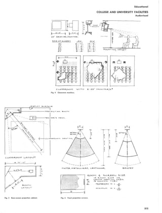
Handicapped Students
width and 4'-4 [132 cm] in length . Desk space
provided in this area shall have a knee clearance
of at least 32 [81 .3 cm] in width and a height
of 27/2 [69.8 cm]. (See Fig. 4.) The number
of desk spaces and accompanying level floor
areas shall be provided as follows:
[92 cm] in width for passage as measured from
the outer edge of the tray slide. (See Fig. 5.)
Self-Service Areas Salad bars, condiment areas,
beverage dispensers, utensil racks, and other
areas where self-service is required shall provide
access within the unilateral vertical reach range
of 20 [50.8 cm] to 48 [121 .9 cm].
Dining Area Tables shall be provided within the
dining area which provide a knee clearance of
at least 271/2 [69.8 cm] in height and 32 [81.3
cm] in width.
Pedestal tables are not recommended because
the center post hinders wheelchair footrests.
Aisle widths shall be at least 6'-0 [183 cm]
as measured from table edge to table edge (Fig .
6, plan A), or 3'-0 [92 cm] from table corner
to table corner (Fig . 6, plan B), in those areas
used by persons in wheelchairs.
The width of main aisles, in areas of normal
traffic pedestrian flow, shall be at least 6'-0
[183 cm] to allow two wheelchairs to pass each
other (Figs. 7 and 8).
CAFETERIAS
Food Lines Food lines of cafeterias shall employ
tray slides no higher than 34 [86.4 cm] in height
and, where a security wall or railing runs the
length of the line, the area shall be at least 36
STANDARD WHEELCHAIR
ELECTRIC WHEELCHAIR
MANUAL WHEELCHAIR
WITH RIM PROJECTIONS
Fig. 7 Fig. E
MIN. SPACE NEEDED UNDER COUNTER OR DESK
Fig. 5
Fig. 6
Lecture hall capacity
Minimum number of
spaces provided
0-50 2
50-100 3
101-200 4
over 200 4 + 1 for each
add'tl 100](https://image.slidesharecdn.com/timesaverbuildingtypesnew-220410120843/85/Time_Saver_building_types_new-pdf-275-320.jpg)
![By KEYES D. METCALF
LIBRARIES, ACADEMIC AND RESEARCH
Formulas and Tables
The figures given here are at best only approxi-
mations and may be altered by local conditions;
they are not arrived at by exact scientific calcu-
lation .
Six groups are dealt with; those relating to:
I. Column spacing
11. Ceiling heights and floor size areas
III . Reader accommodations
IV. Book storage (excluding problems that
are affected by column spacing)
V. Card catalogs
VI. Government standards
Planning Academic and Research Library
Buildings, McGraw-Hill Book Company, New
York . 1965.
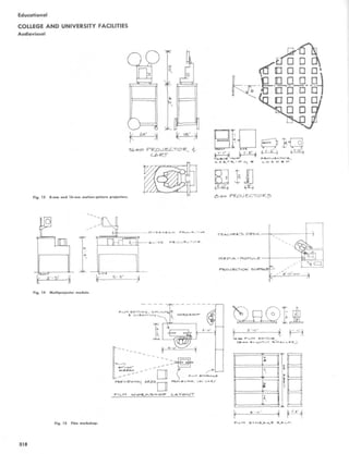
'Columns should not be wider than the depth of range. 14 by 14 in. up to 14 by 18 in. is suggested.
TABLE 2 Square Modules with Column Spacing Multiple of 3 ft'
Columns should not be wider than the depth of the range. 18 by 32 in. is suggested.
Frg. 9
Educational
COLLEGE AND UNIVERSITY FACILITIES
Libraries
aisles at right angles to the ranges is also of
importance . (See Fig. 10.)
If practicable, columns should be no greater
than 14 in. in the direction of a range, and the
dimension in the other direction should be kept
down to 18 in. If over 14 in . in the direction of
the range is necessary, the column might al-
most as well be 32 in. in that direction. It could
then occupy the space of a full stack section
and perhaps enclose a heating duct. If a column
is wider than the range, it will jut into the stack
aisle. Irregular length stack sections are incon-
venient, and can often be replaced to advantage
by a lectern or consultation table.
Tables 1 and 2 deal with standard layouts in
commonly used module sizes .
The following comments may be useful in
connection with Tables 1 and 2.
1 . Spacing 3 ft 9 in. or less should be used
for closed-access storage only, with ranges not
more than 30 ft long and not more than 16 in.
deep.
2 . Spacing 3 ft 9 in . to 4 ft 1 in. can be used
to advantage for large, little used, limited-ac-
I . Column Spacing
A. Stack Areas No one size is perfect for column
sizes or column spacing.
Other things being equal, the larger the bay
size, the better .
Column spacing-that is, the distance be-
tween column centers-is generally more im-
portant in concentrated stack areas than in
combined stack and reading areas because in
the latter suitable adjustments are easier to
make .
Clear space between columns-this is not
the space between column centers-in a col-
umn range should preferably be a multiple of
3 ft (plus an additional 4 in. to provide for ir-
regularities in the column sizes and for the end
uprights in the range) .
Range spacing and range lengths have a
greater effect on book capacity than the dis-
tance between columns in a column range. The
reduction of space between range centers by 1
in. increases book capacity by approximately 2
percent. The reduction of space used for cross
!AMPS
graft A ramp shall be at least 4' [122 cm] in
+,dxh-
LesyflU The inclined section of a ramp shall not
eueed 30' [9 .14 m] in length . At both ends of
each 30' [9.14 m] (or smaller) section and at each
srrrrirg point shall be a level area of at least
6' [183 cm) in length and the width of the ramp.
adewM In modifying existing spaces: If an
area to be romped has a vertical drop of 3
7.6 cm) or less and is situated either in an open
^rea or at a door with no closing-device pressure,
-- _- gradient of not greater than 1 :4 (25%)
ee used .
An Modifying Existing Spaces If an area to
be romped has a vertical drop of 2 [5.1 cm]
or less and is situated at a door with a closing-
device pressure, then a gradient of not greater
*bon 1 :6 (16.66%) shall be used.
In New Construction Any vertical drop over
'-j' [1 .27 cm] shall be ramped using a gradient
not greater than 1 : 12 (8.33%) and preferably
1 : 16 (6.25I) where feasible . (See Fig. 9.) TABLE 1 Square Modules with the Column Spacing a Multiple of 3 ft
(Plus 1'/~ ft for the Column itself)'
Sections
between
columns, Ranges to Range spacing
Bay size standard 3 ft a bay on centers
19 ft 6 in . by 19 ft 6 in. 6 5 3 ft 10% in.
6 4 4 ft 10y in.
6 3 6ft6in .
22 ft 6 in. by 22 ft 6 in . 7 6 3 ft 9 in.
7 5 4 ft 6 in.
7 4 5 ft 7y in.
25 ft 6 in. by 25 ft 6 in . 8 7 3 ft 7/, in .
8 6 4 ft 3 in.
8 5 5 ft 1 y, in.
B 4 6 ft 4y, in.
28 ft 6 in. by 28 ft 6 in. 9 8 3 ft 6/, in.
9 7 4 ft Oy, in.
9 6 4h9in.
9 5 5 ft 8% in.
Bay size
Sections
between
columns
standard 3 ft
Ranges to
a bay
Range spacing
on centers
18 it by18ft 5 5 3ft7y,in.
5 4 4ft6in .
5 3 6 ft
21 ft by 21 ft 6 6 3 ft 6 in.
6 5 4 ft 2/s in .
6 4 5 ft 3 in .
24 ft by 24 ft 7 7 3 ft 5y, in .
7 B 4 ft
7 5 4 ft 9'/ in .
7 4 6 ft
27 ft by 27 ft 8 8 3 ft 4y2 in .
8 7 3 ft 10% in.
8 6 4ft6in .
8 5 5 ft 4/., in .
8 4 6 ft 9 in .](https://image.slidesharecdn.com/timesaverbuildingtypesnew-220410120843/85/Time_Saver_building_types_new-pdf-276-320.jpg)


![considered before the building is planned,
because such items as conduits, storage racks,
acoustics, equipment, furniture, electrical out-
lets, glazed doors for supervision, and cata-
loging methods determine much of the utility
of the music room.
Commuters' Areas Nonresident students at col-
leges near or in metropolitan centers afford
many problems to unions, a number of which
center around their nonparticipation in most
of the union's programs . Their demands on the
college naturally differ from those of the resi-
dents. They need parking space on the campus,
a place to eat a bag or light lunch, storage place
for books, lunches, and similar equipment, e
spot for resting or, perhaps, an occasional
overnight stay . While the union is not neces-
sarily the only location on the campus where
such services may be rendered, it seems to be
the logical place for many of them . Further-
more, many of the day students are quite
likely to eat in the union and to use it as their
headquarters, and so it seems logical to plan
to meet as many of their demands As possible
in advance. If the union building is to be a uni-
fying factor on the campus, it must be prepared
to serve the offtimes large[nonresident]seg-
ment of the student body.
Guest Rooms Many union buildings contain
overnight guest facilities, the extent of which
ranges from a single room or suite through
large, barracks-like halls to elaborate hotels
with full commercial service. The facilities may
be intended primarily for university guests,
such as convocation speakers, for visiting
groups such as athletic teems, for parents or
returning alumni, for the guests of students or
for conventions. They add to the service as-
pects of the union building and offer little to its
educational program aside from the training
the larger units afford to student employees
and to students who are majoring in hotel
administration . The inclusion of guest rooms
in the union building depends upon many di-
verse elements, such as present and future
needs, facilities existing elsewhere, nearby
hotels, curricular development, operating
hours, operating costs and other union facili-
ties, and careful study is indicated. The fact
that the Association of College Unions lists
hotel units among the doubtful facilities to be
included in union buildings should serve to re-
inforce the need for careful study.
Student Activities Area A student activities area
is a space housing a number of desks and filing
cabinets which can be used by varying student
organizations for a portion of the academic
year. Thus groups which do not need an office
or room of their own can be accommodated
with a minimum of space allocation . The num-
ber of groups end activities on each campus
that might use such an area determine its size,
and it appears wise to consider that the exis-
tence of such an area might well increase re-
quests for its use, thus making a somewhat
oversized original plan advisable.
Theater
Need Like so many other parts of the union
building, the theater must be custom-built to
suit its campus . It is quite likely that a union
building located near a modern, well-equipped
theater can utilize these facilities for its pro-
gram and not need a theater of its own. On the
other hand, the demands on such a theater by
dramatic and other groups may render the the-
ater unavailable for the variety of activities
Educational
COLLEGE AND UNIVERSITY FACILITIES
Student Unions
which the Classified Facilities Table indicates
may be held therein, thus making desirable the
inclusion of a theater in the union building .
With a well-housed drama program already in
operation, the theater requirements may be
pared down so that nothing more than an audi-
torium and platform suits the union's needs.
Such a solution appears most questionable,
however, since it provides little more than a
forum for speakers, a location for motion pic-
tures and stage for formal music concerts.
Such activities as variety or vaudeville shows,
fashion shows, orchestral and choral concerts,
sing contests and dance recitals become diffi-
cult to present without proper stage, scenery,
dressing, shops, wing and lighting facilities .
The use of road shows-ballet, drama, opera,
and the like-by the union is obviated . It may
be that such activities can be housed else-
where, but the demands on theaters of dramatic
groups for practice and for rehearsal and
staging time, of music groups for practice and
concert time, of assemblies, meetings and con-
ferences for auditorium time, of departments
and organizations for space for motion pic-
tures, lectures and demonstrations, indicate
that a close study of all present demands upon
theater facilities be studied and that future pos-
sibilities, particularly as suggested by other
campuses with adequate union theaters, be
considered before plans are drawn up. The
place of other existing theaters and assembly
halls in the campus scheme of things, including
policies governing their use, should be given
grave consideration.
A union theater would seem to suit most of
its purposes if it houses the requirements of a
fairly orthodox collegiate drama program and
adds such items as an elevating forestage-
orchestra pit; audience access to stage for
variety shows, sing contests end the like ;
fluctuating seating capacity by means of sliding
panels or draperies; reception or lobby lounge ;
broadcasting facilities; possible combination
craft-scenery shops, and still and motion-
picture equipment to achieve the flexibility
which is an earmark of the union building .
To function completely, the union theater
would be composed of:
Auditorium Projection booth
Stage Sound system
Forestage Screen
Orchestra pit Stage house
Proscenium arch Lobby
Dressing rooms Ticket office
Scene shop Scenery storeroom
Costume shop Control board
Light booth Rest rooms
Makeup room Coat room
Rehearsal room Lounge or green room
Some of these facilities, such as lounge,
coat room, rest room or rehearsal room, may
be a part of the union building and serve a
double purpose, so that a nearby lounge may be
used for receptions or a properly shaped
meeting room double for use during live re-
hearsals .
Arts and Crafts Shops
The variety of offerings which the union's
shops can provide is large. Some of these
offerings, such as photography, demand spe-
cialized facilities and equipment; others, such
an leatherwork or jewelry making, require little
and can be accommodated in a general shop
area. The tools of some crafts may be used in
common by participants in other union activi-
ties, so that the scene, maintenance, and wood-
working shops may use the same power tools
and central materials sources and the camera
club and campus publications the same stu-
dios. The size of the union and the university,
the organizational scheme and expected use of
the various shops would determine the pos-
sibility of such a combination. Among the arts
and crafts activities which a union might
embrace are :
Painting General woodworking
Sketching Picture framing
Block printing Cabinet making
Poster making Metal and jewelry work
Silk screening Ceramics
Clay modeling Drafting
Weaving Photography
Rug making Leatherwork
Drawing Graphic arts
Fly tying Sewing
Plastic work Knitting
While adherents of nearly each art or craft
could develop a list of reasons why their favor.
its activity should be allocated separate space
and equipment, much of it with special require-
ments such as north light for sketching or hu-
midity control for clay modeling, enough com-
promises and combinations can be effected to
provide a variety of activities within a reason-
able area.
Outdoor Games
The extent to which the games area should be
developed is dependent in large degree on what
is available elsewhere on the campus. The num-
ber of games within the union's province which
can be played outside might include badminton,
bowling on the green, boccie, croquet, curling,
clock golf, horseshoes, shuffleboard, table
tennis, giant checkers, deck tennis, roque,
quoits, and a variety of table games such as
chess, checkers . or cards.
Integration of Areas
Some union facilities must be located on the
street level; others operate most efficiently on
other levels . There are strong reasons for
placing food services, information center,
bookstore, ticket offices, ballroom, and admin-
istrative offices on the ground floor, while
other areas such as publication offices or stu-
dent activity offices may be in less accessible
locations. Guest rooms, which receive rela-
tively little traffic and function better in qui-
et, fit nicely into higher floors and more remote
wings. The task of putting the various elements
of a union building together so that each fulfills
its own function while complementing that of
the others is nearly certain to demand com-
promises. Realism may dictate that such reve-
nue-producing facilities as a bookstore or soda
fountain take precedence in location over a
music room or browsing library, even though
it may be educationally desirable to expose, at
least by propinquity, those entering the
building to the latter rather than the former.
Traffic to the most popular areas of the union
building should not be so directed that it
causes great crowds of people to throng its
passages and stairways to the disturbance of
other sections and to the detriment of building
maintenance. Some seldom-used facilities,
such as a ballroom or hobby shop, may finally
be placed on the top floor because there is no
room elsewhere for them.
Segregation by Function Whenever practical, ar-
eas should be separated by function, as previ-
ously described in the section on game rooms,
where supervision, instruction, and equipment
control for all were made possible . Such areas](https://image.slidesharecdn.com/timesaverbuildingtypesnew-220410120843/85/Time_Saver_building_types_new-pdf-307-320.jpg)


![Cultural
SMALL MUSEUMS
PLANNING THE SMALL MUSEUM
The objective of the proposed museum should
be clearly defined, as well as the geographic re-
gion, the subject (history, natural history, or art)
and extent of display and other services .
The following is an example of a suitable basic
statement for a small museum :
The basic objective of the Museum is to collect, pre-
serve, study and exhibit significant objects of the com-
munity, and provide related educational services in
order to increase public knowledge and stimulate cre-
ative activity.
This statement should have further definition
by incorporating a reference to the type of collec-
tions, whether human history, natural history or
art.
A good museum includes these basic functions :
(1) curatorial, (2) display, (3) display preparation,
(4) education . In order to realize both objectives
and functions, certain facilities and spaces are
essential .
There must be sufficient diversification of
spaces to allow each function to be undertaken
separately while at the same time combining cer-
tain activities in a single area as required for
economy in a small museum . Because of the many
and varied kinds of tasks which a museum has
to perform, it is absolutely impossible to maintain
good housekeeping and curatorial procedures
without separation of functions into separate
rooms . This relation between functions and physi-
cal facilities is summarized in the following .
The Technical Requirements of Small Museums,
Raymond O . Harrison, M.R .A] .C . Technical Paper No .
1, Canadian Museums Association, Ottawa, Ontario,
1966 .
Fig. 1 Space organization diagram .
Functions Space required
l . Curatorial Functions
a. Collection, preservation, identification, documentation, study, restora- a . Office-workroom, Workshop
tion .
b. Storage of collections. b . Reserve Collection Room
2 . Display Function
Thematic and changing displays of selected objects and . documents from Display Gallery
the collections arranged to tell a story .
3 . Display Preparation Function
The preparation of exhibits. Workshop,
Office-workroom
4 . Educational and Public Functions
This term has been expanded to include all public functions . .
a . Lectures, school tours, society meetings, films, and social functions . a . Lecture room,
Chair storage closet,
Kitchenette
b . Reception, information, sales, supervision of display gallery . b. Lobby
Sales and Information Counter
c . Public requirements . c. Cloak room,
Washrooms
S . Other Services
a . Mechanical . a . Heating-ventilation plant
b . Janitorial . b . Janitor's closet](https://image.slidesharecdn.com/timesaverbuildingtypesnew-220410120843/85/Time_Saver_building_types_new-pdf-355-320.jpg)


![Cultural
LIBRARIES
Library Location
5. Every public service area should be sup-
ported by book storage, office, and work areas.
Reading rooms should be grouped so that they
may be served by common book storage, office,
and work area .
6. A librarian or attendant should not be
responsible for areas more than 55 ft beyond
his desk .
7 . Load bearing walls should be kept to a
minimum and maximum use of shelving and
furniture made to separate different service
areas .
Other factors, such as exterior light and
noise, also may influence the location of vari-
ous areas within the building .
Finally it may be said that the success or
failure of a building is measured by the degree
to which planners succeed in applying the fore-
going principles of desirable interrelation-
ships . Whether it is a simple village library or a
complex large-city library, every effort should
be made to facilitate supervisory control, flexi-
bility, and convenience of readers . Careful at-
tention to supervisory control together with a
flexible layout of public services will pay off in
savings in staff time and ability to handle peak
loads with a minimum staff . By the same token,
failure to achieve effective service and space
relationships can be a financial burden for
many years and the source of continuing incon-
venience for countless readers .
LIBRARY LOCATION
Central Location
A library is a service organization intended to
serve people . Therefore, it should be centrally
located where it will be accessible to the
largest number of potential readers and infor-
mation seekers .
This principle is neither new nor revolution-
ary . It has been advocated by a vast majority of
experienced public library administrators for
well over a half century . The concept of a cen-
trally located library is just as valid now when
there are more than 70 million registered motor
vehicles as it was when the first successful
American automobile was introduced in 1892 .
A central location is usually associated with
a heavy concentration of retail stores, office
buildings, banks, public transportation points,
and parking facilities . This means that it Ithe
public library] should be near the center of
general community activity, i .e ., the shopping
and business district . Just as dime store opera-
tors study the flow of pedestrian traffic before
locating one of their units, so should library
planners consider carefully the best location to
reach John O . Public. A building located just
around the corner from the most advantageous
spot can lose a great deal of its potential pa-
tronage
.-The
importance of a central location was re-
affirmed in this statement : A prominent,
easily accessible location is required to attract
a large number of persons . Therefore the li-
brary should be placed where people naturally
converge-in the heart of the shopping and
business district, rather than in a remote loca-
tion such as a park, civic center or quiet side
street .' The American Library Association's
standards for public library service also empha-
size the need of maximum accessibility.
Unquestionably, a location which affords
maximum accessibility to the greatest number
of people is fundamental to the success of
° Russell J . Schunk, Pointers for Public Li-
brary Building Planners (Chicago : American
Library Association, 1945), p . 6 .
sCharles M . Mohrhardt and Ralph A . UI-
veling, Public Libraries, Architectural Rec-
ord, December, 1952, p . 152 .
Fig. 6 Table space requirements for readers.
Fig. 5 Minimum clearances for people and equipment in reading rooms.](https://image.slidesharecdn.com/timesaverbuildingtypesnew-220410120843/85/Time_Saver_building_types_new-pdf-367-320.jpg)