Computer aided drawing (CAD) provides advantages over manual drawing such as increased speed, accuracy, and ability to electronically share drawings. However, CAD requires retraining staff and removes individual drawing styles. Some companies may retain manual techniques due to equipment and training costs.
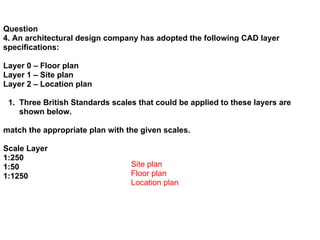
Architectural design companies use CAD "layering" to separate drawings into distinct layers like foundations, floor plans, wiring, and plumbing. This allows separating drawings for different users and customizing views.
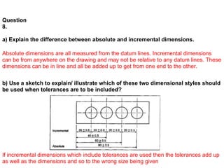
Standard drawing conventions like British Standards improve understanding between parties and ease information sharing. Dimensional tolerances specify acceptable component fits and enable manufacturing of interchangeable parts.