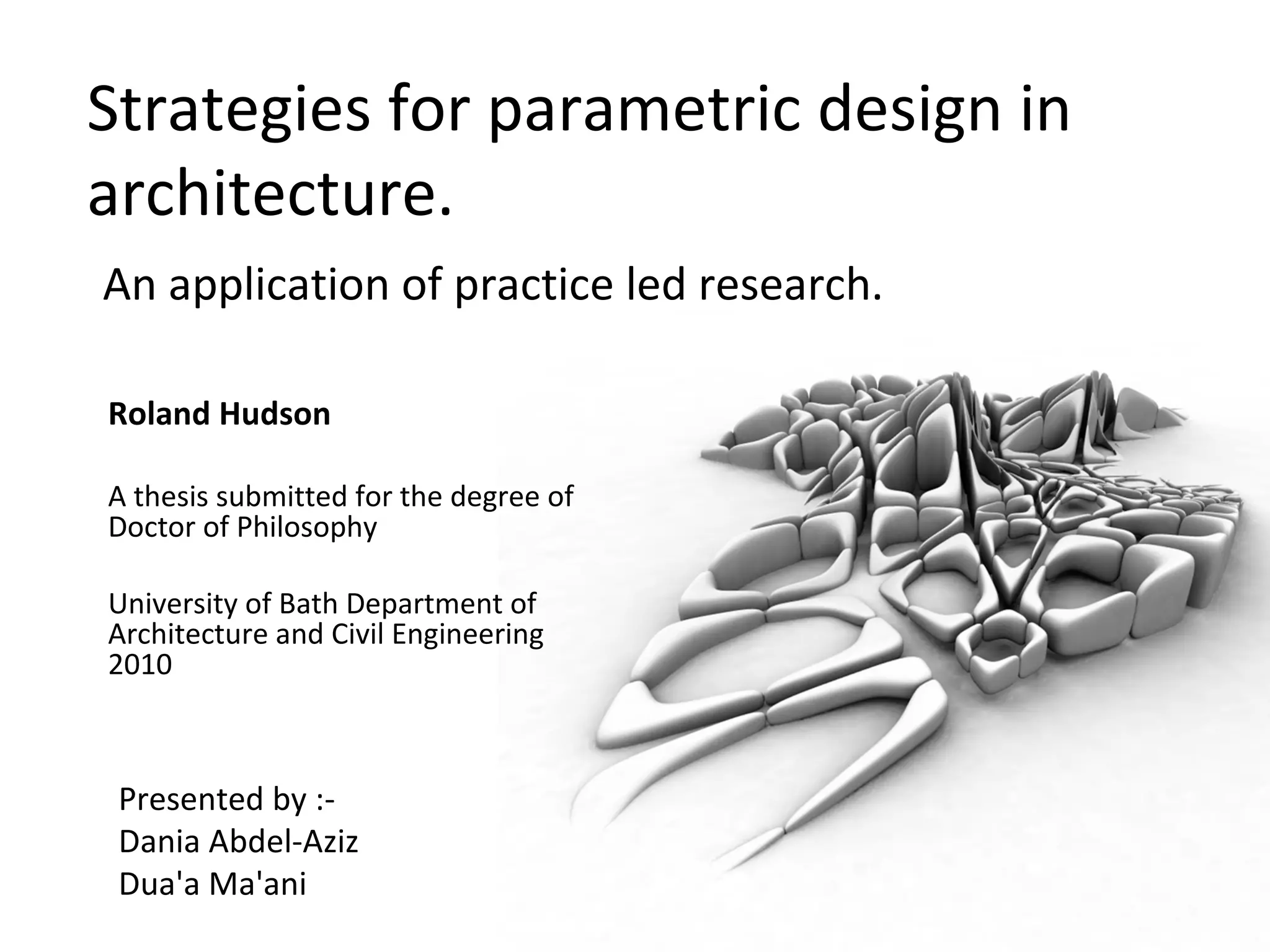
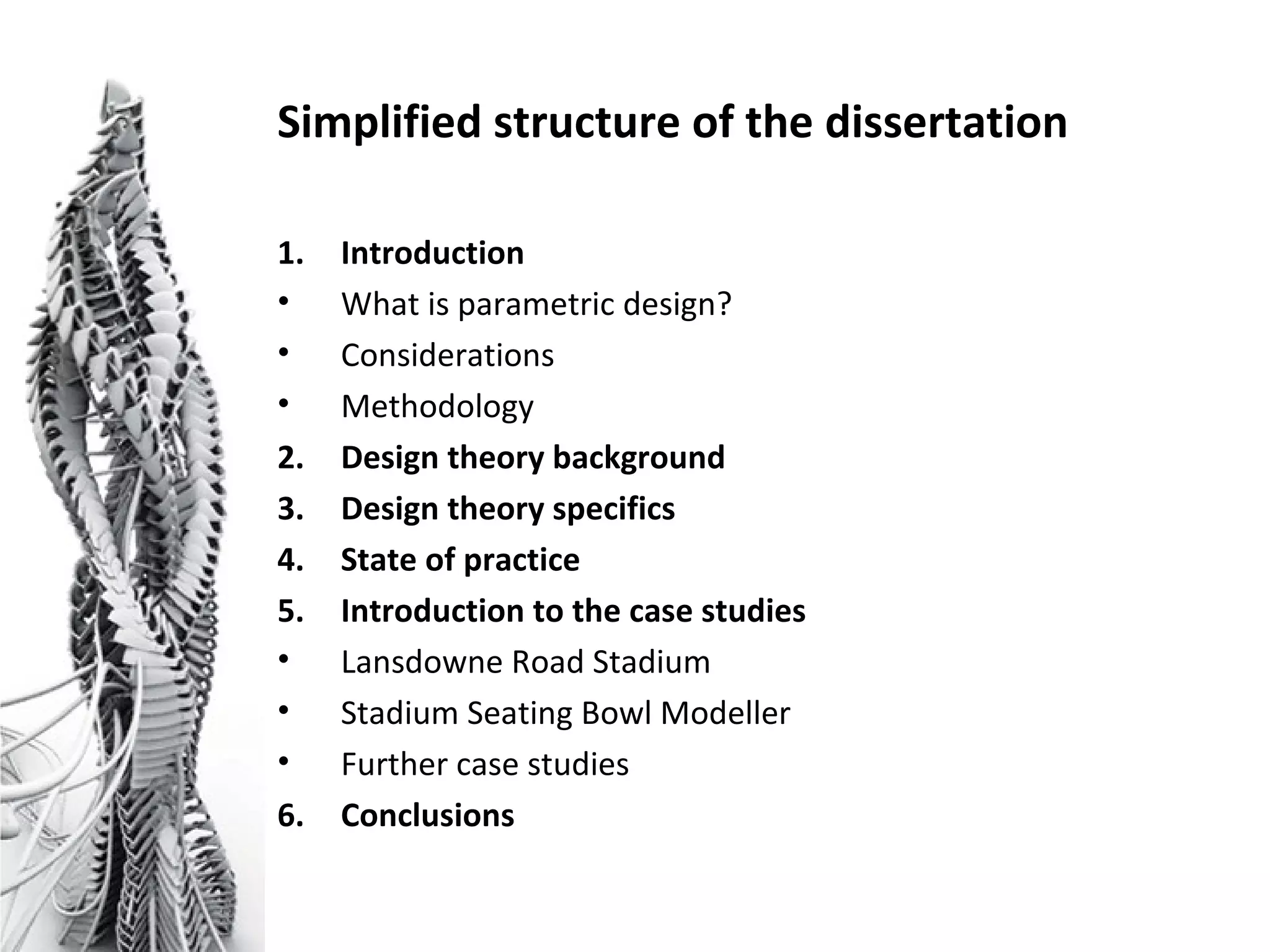
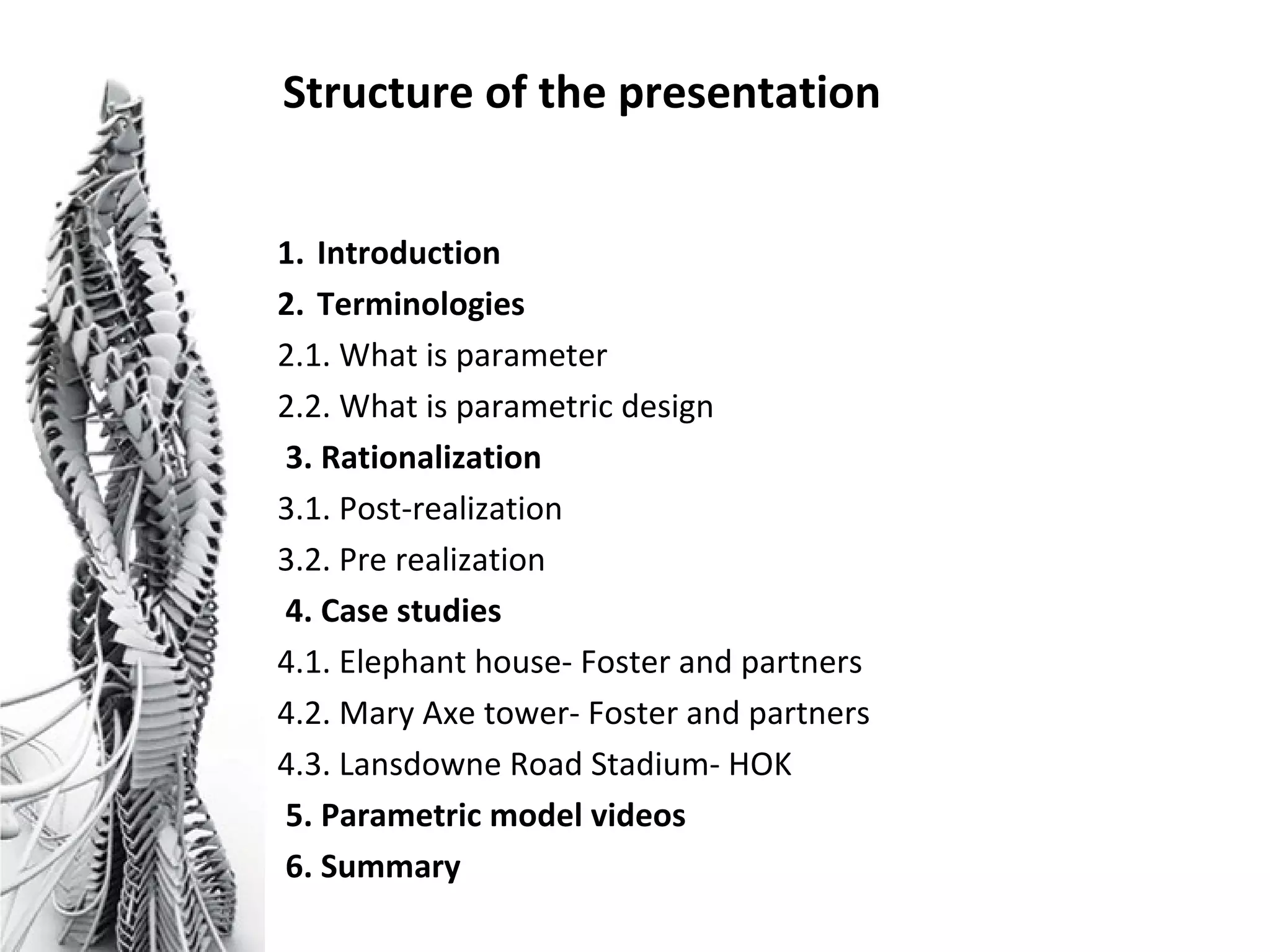
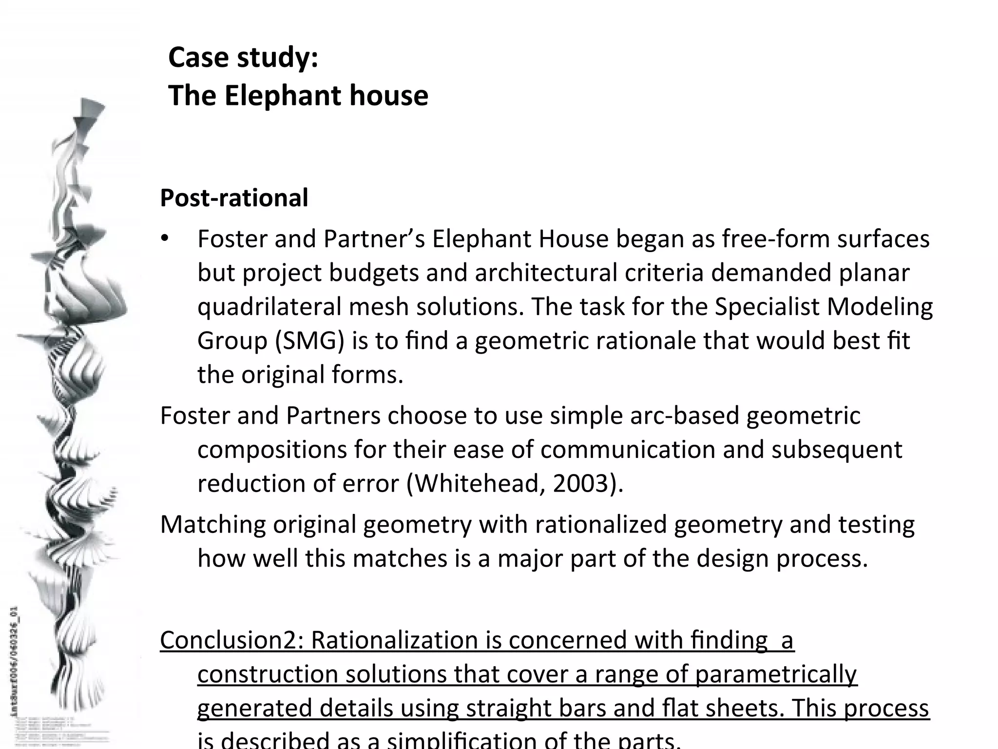
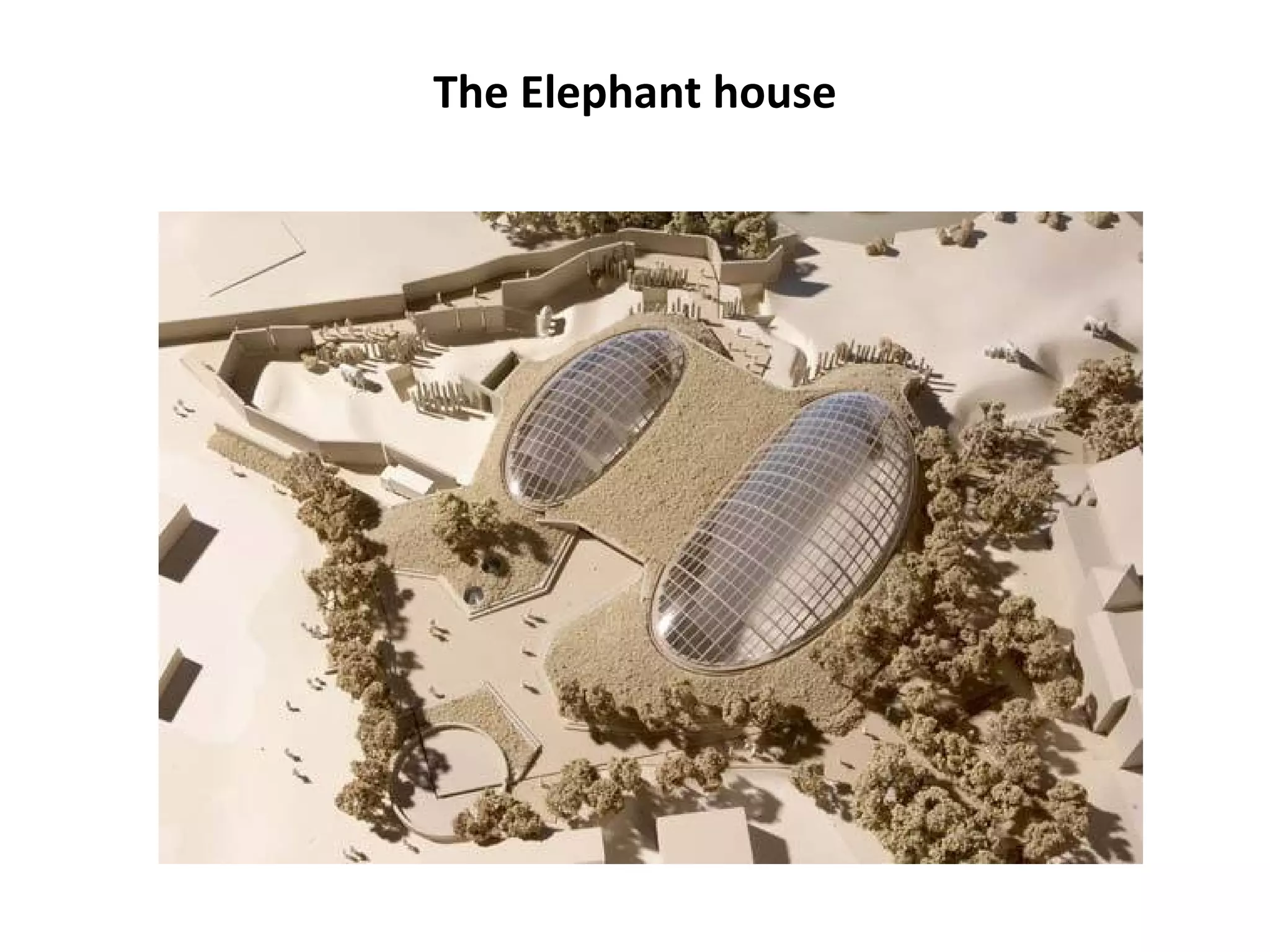
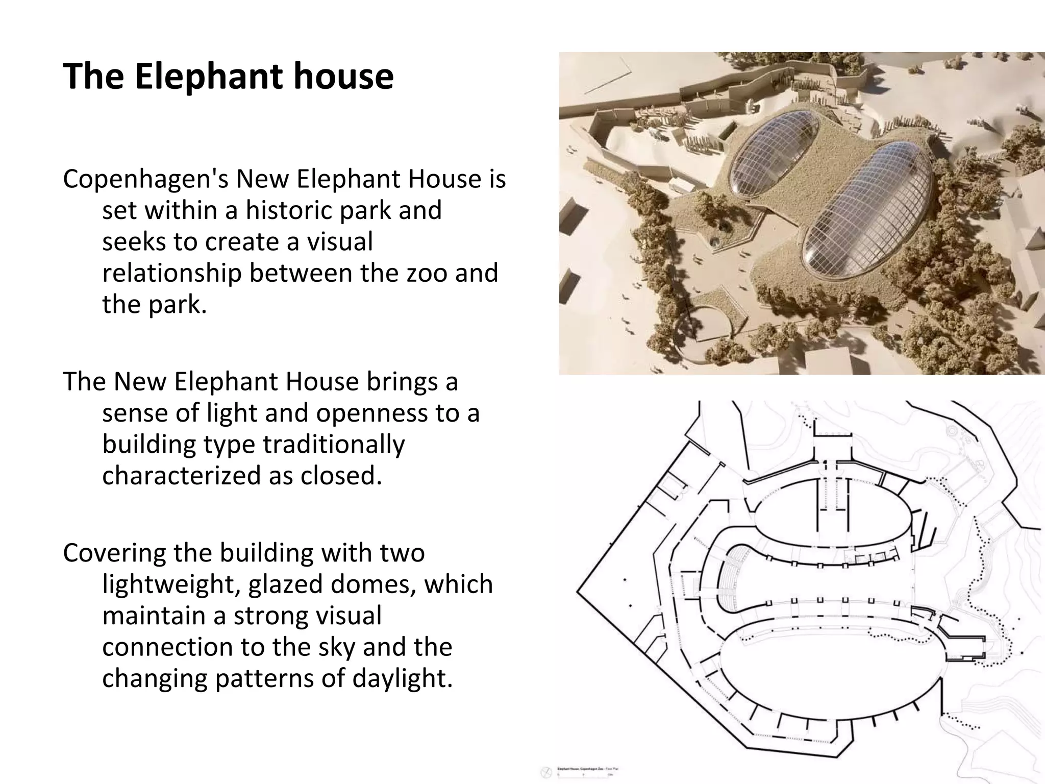
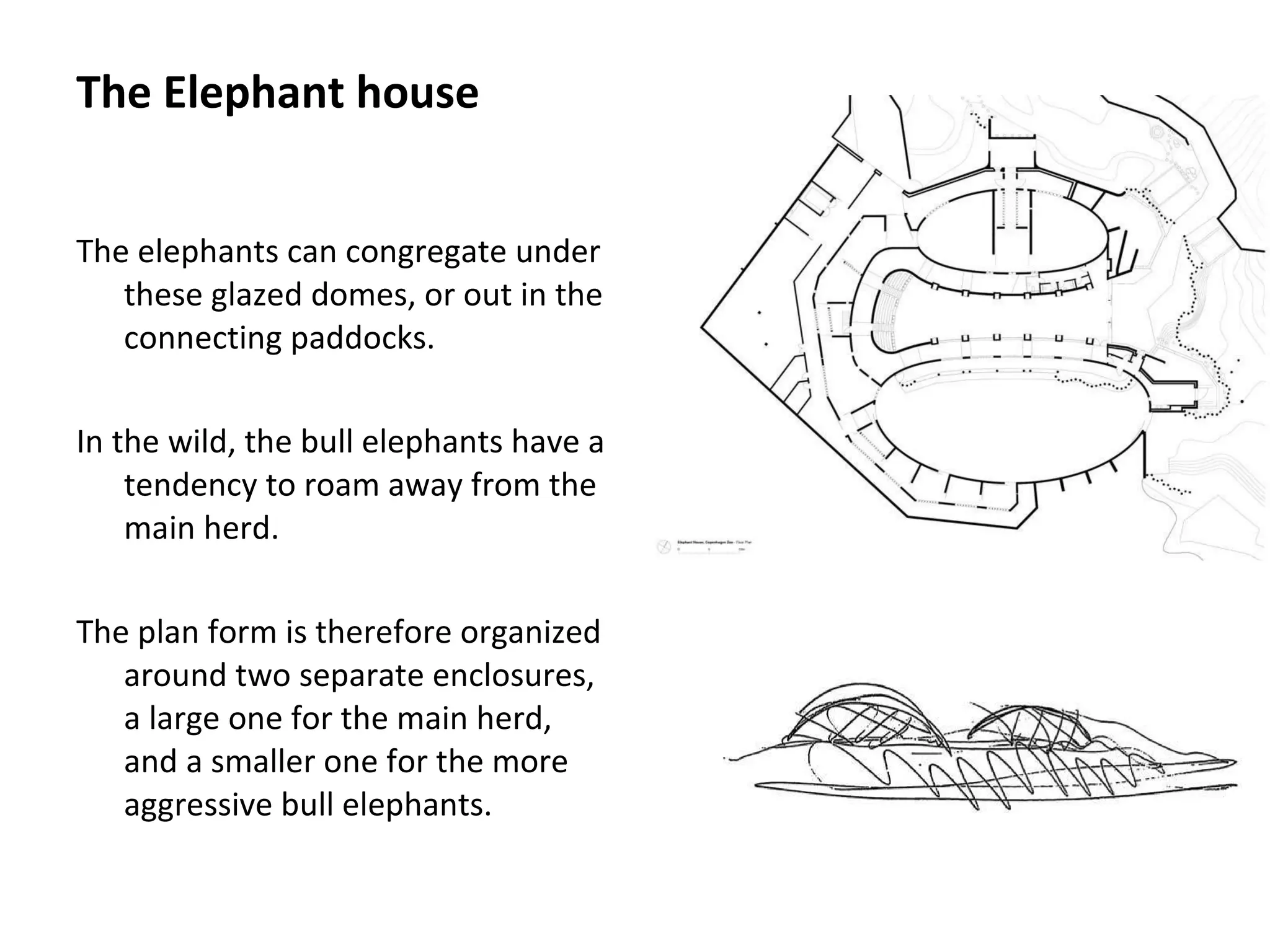
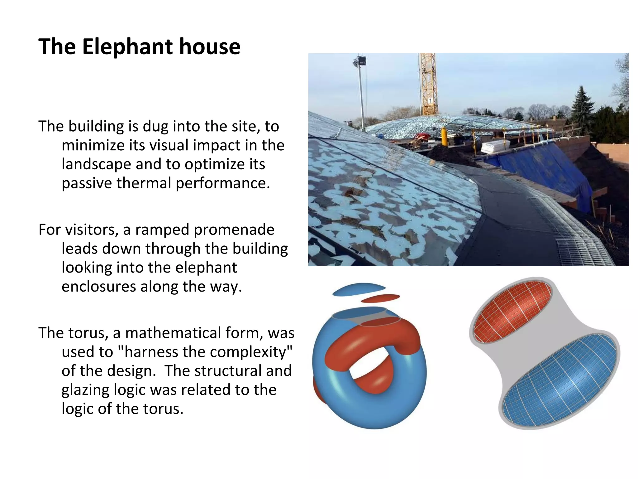
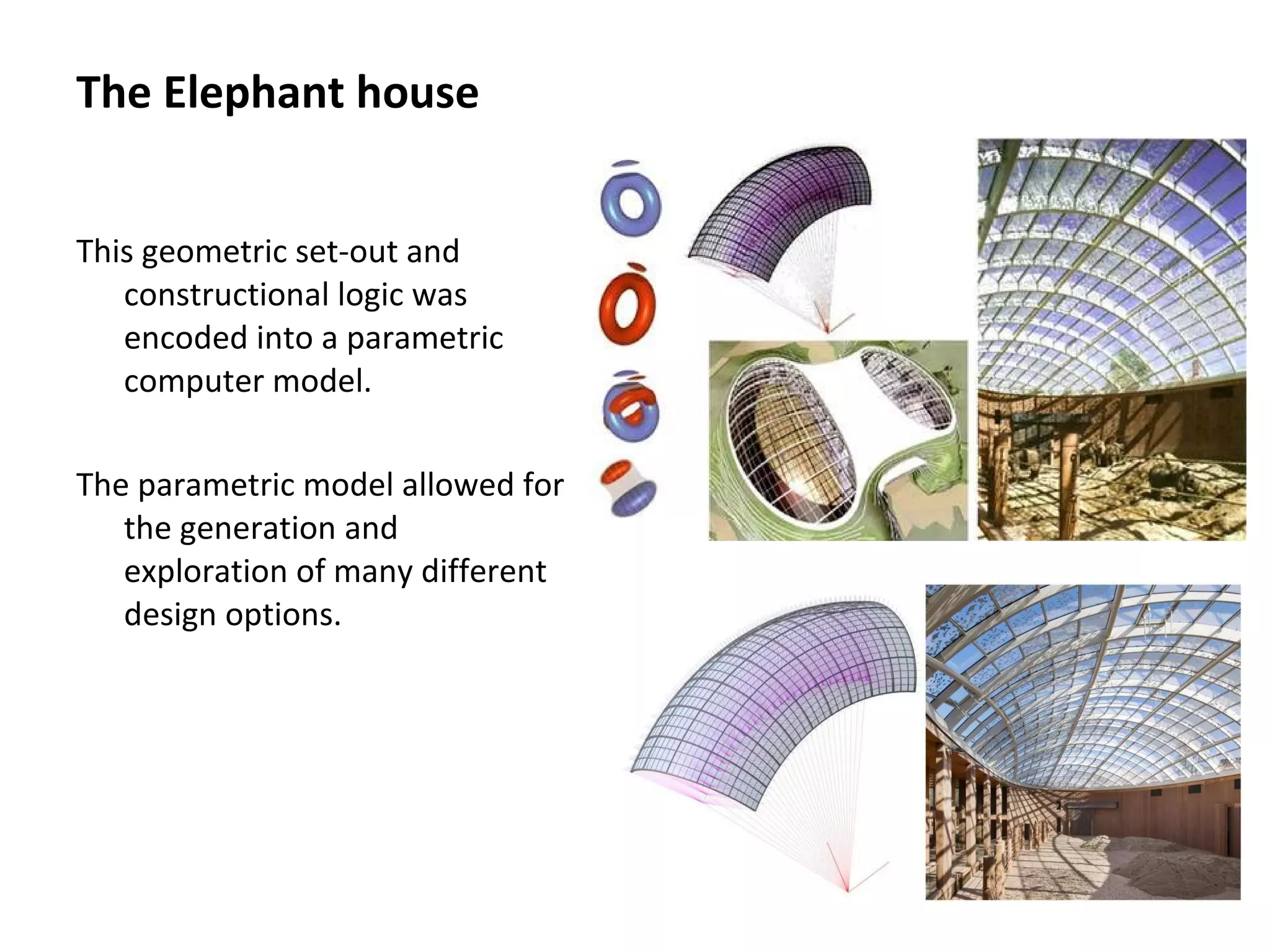
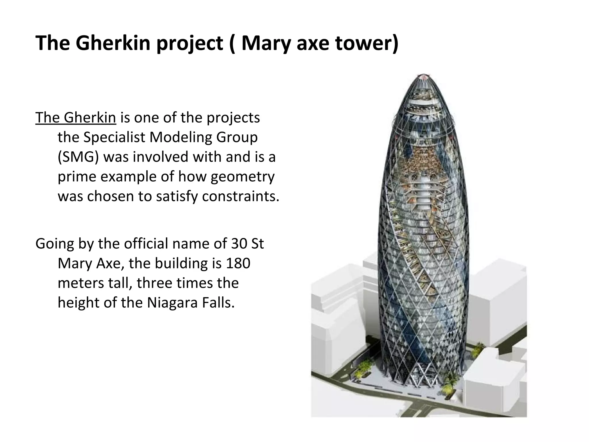
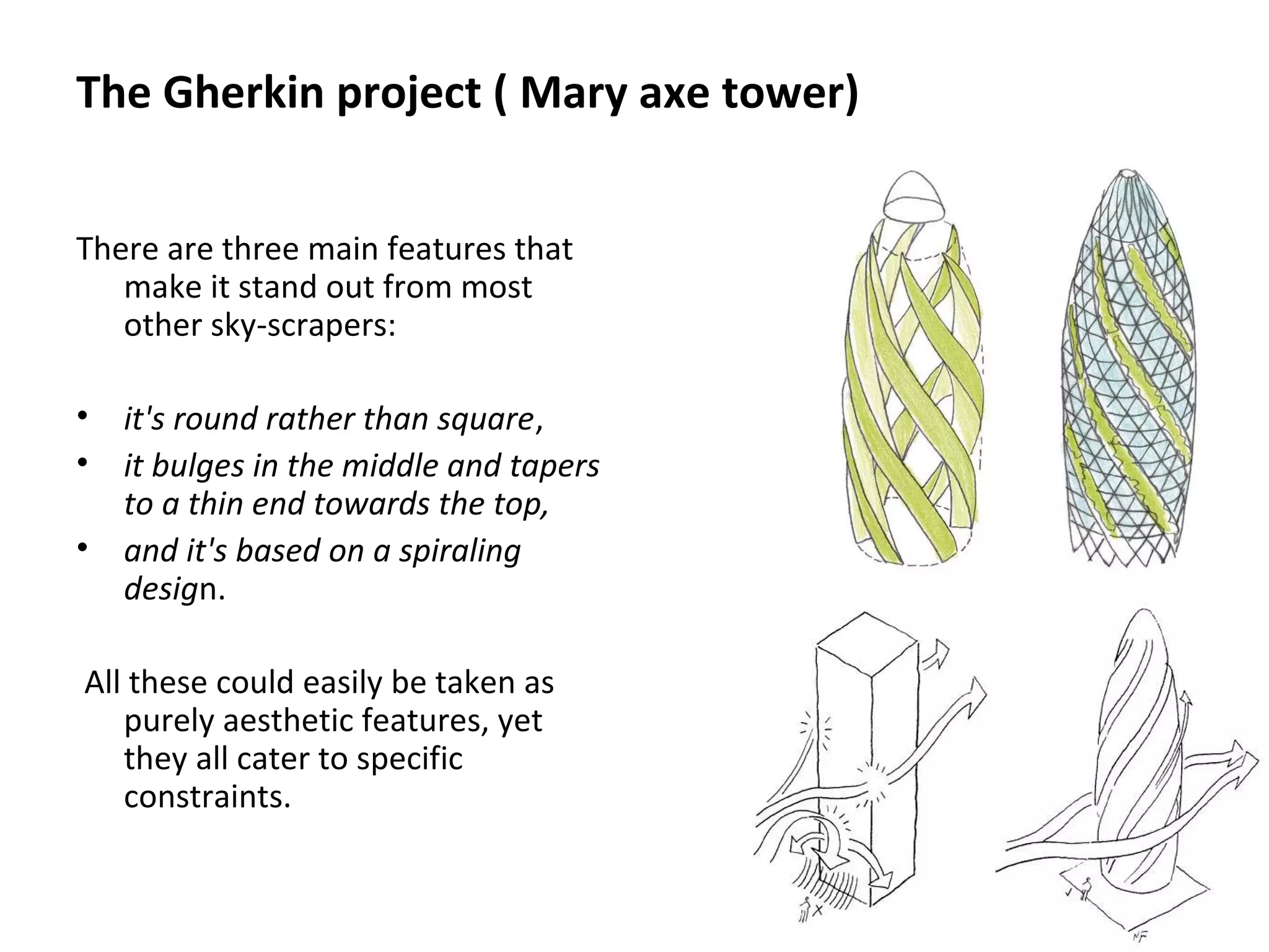
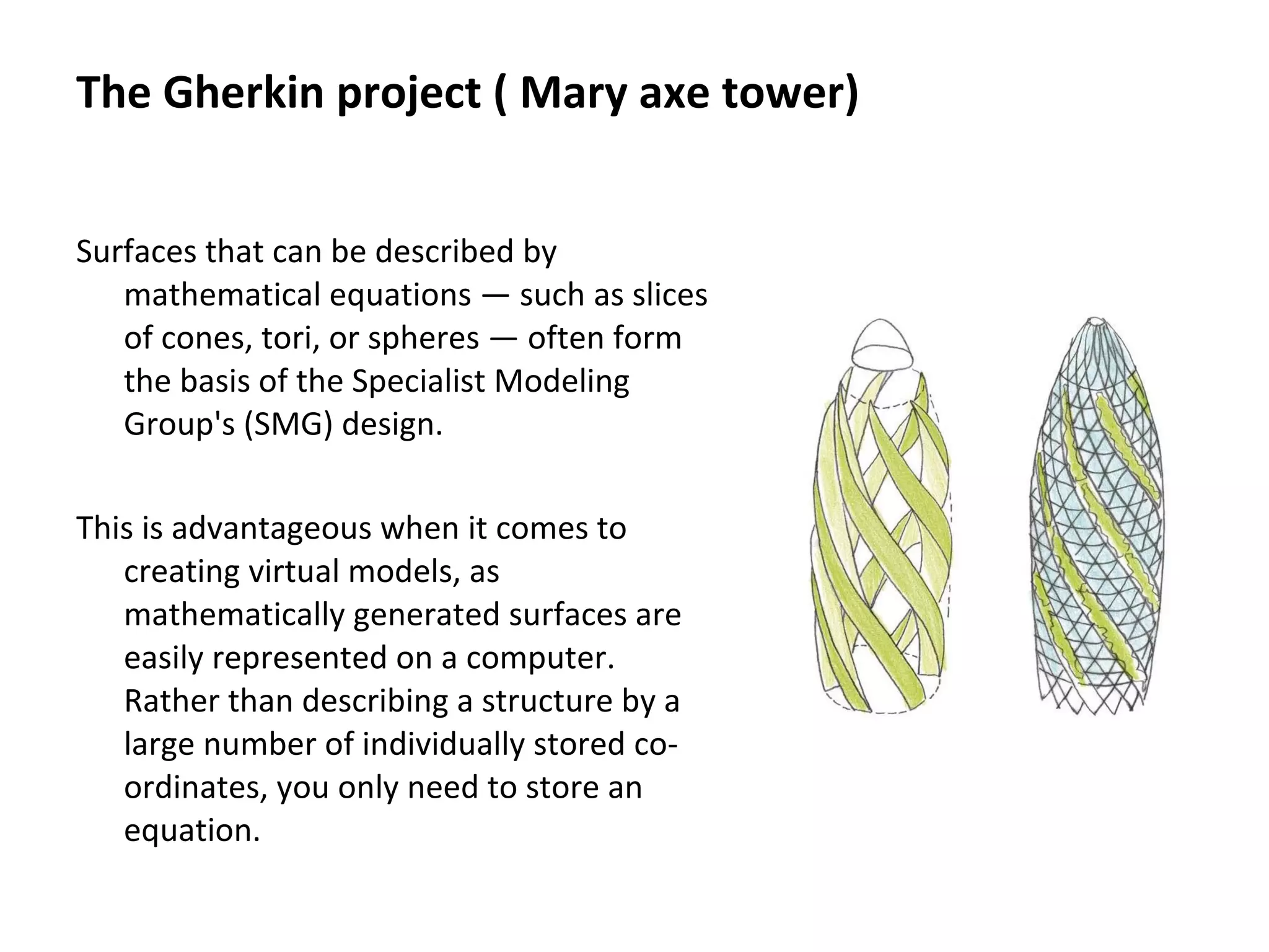
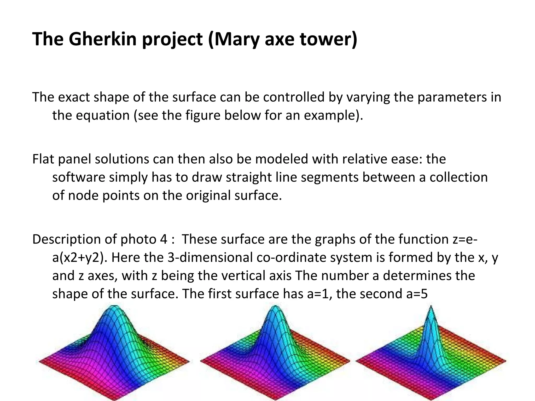
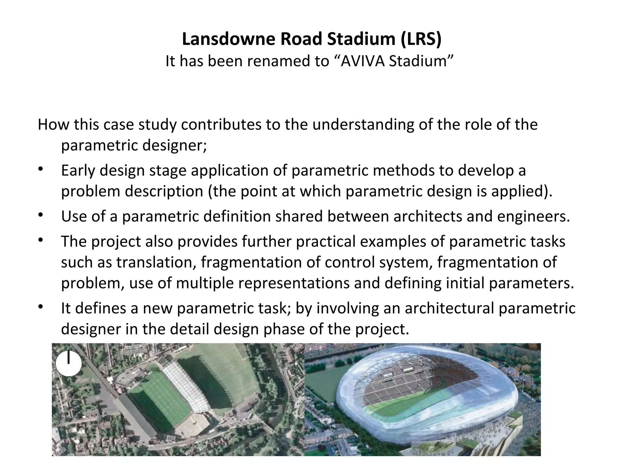
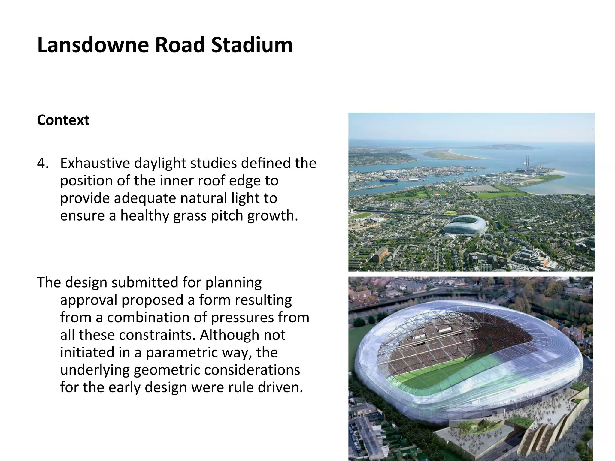
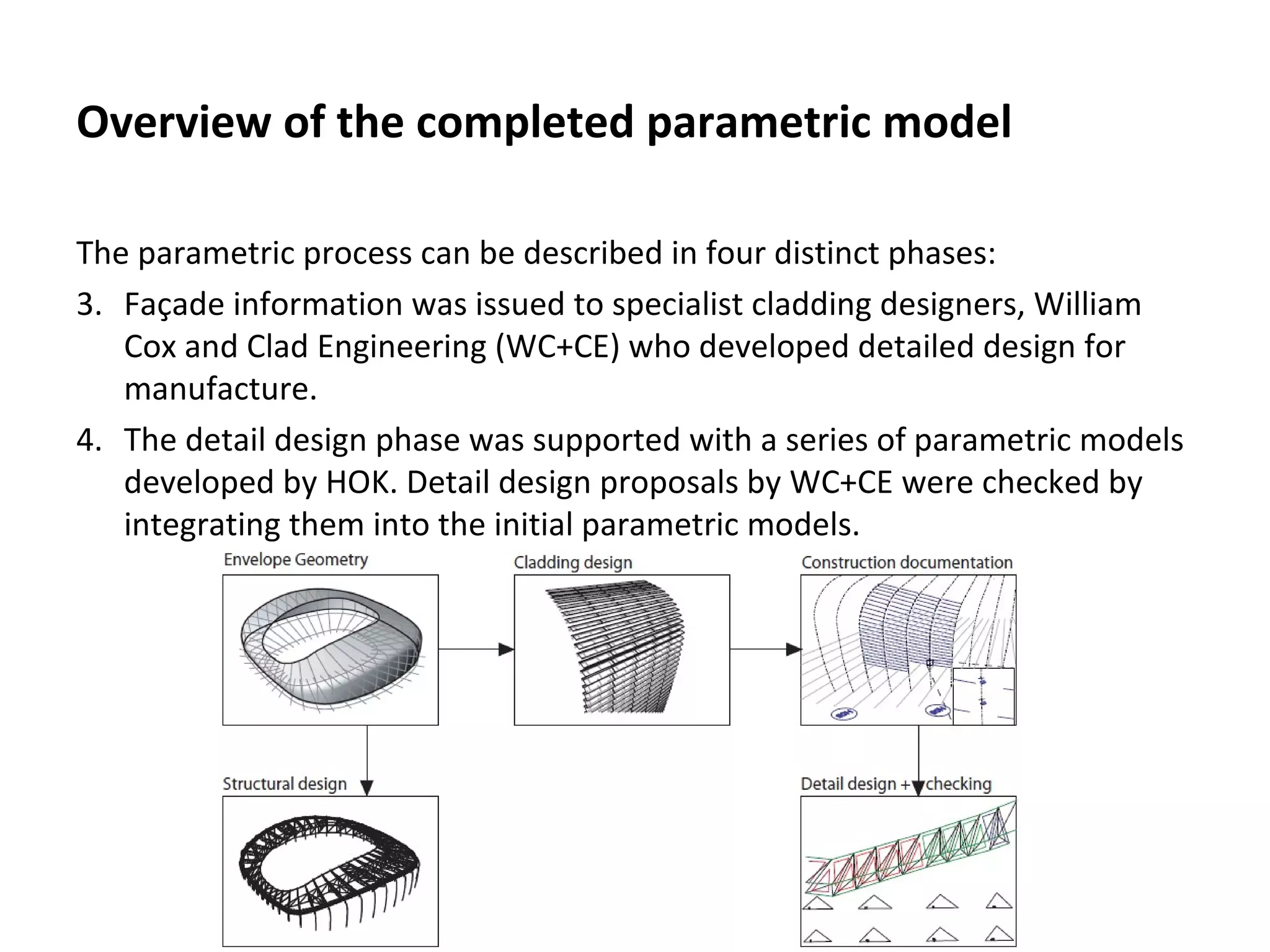
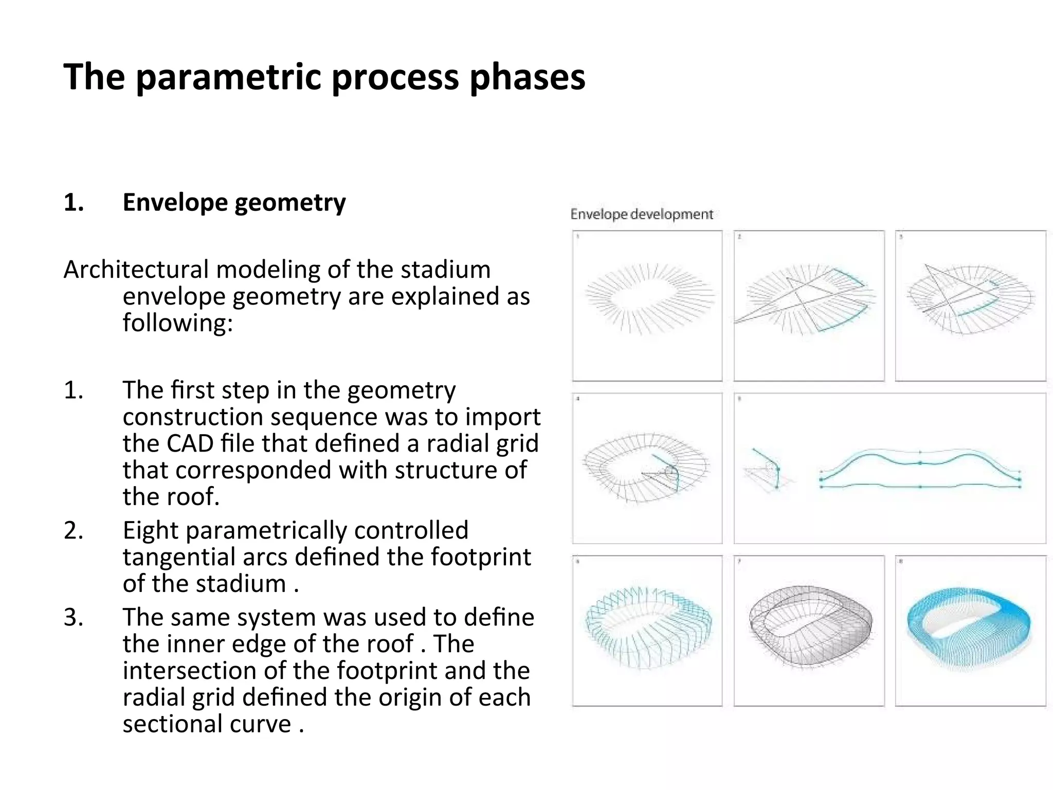
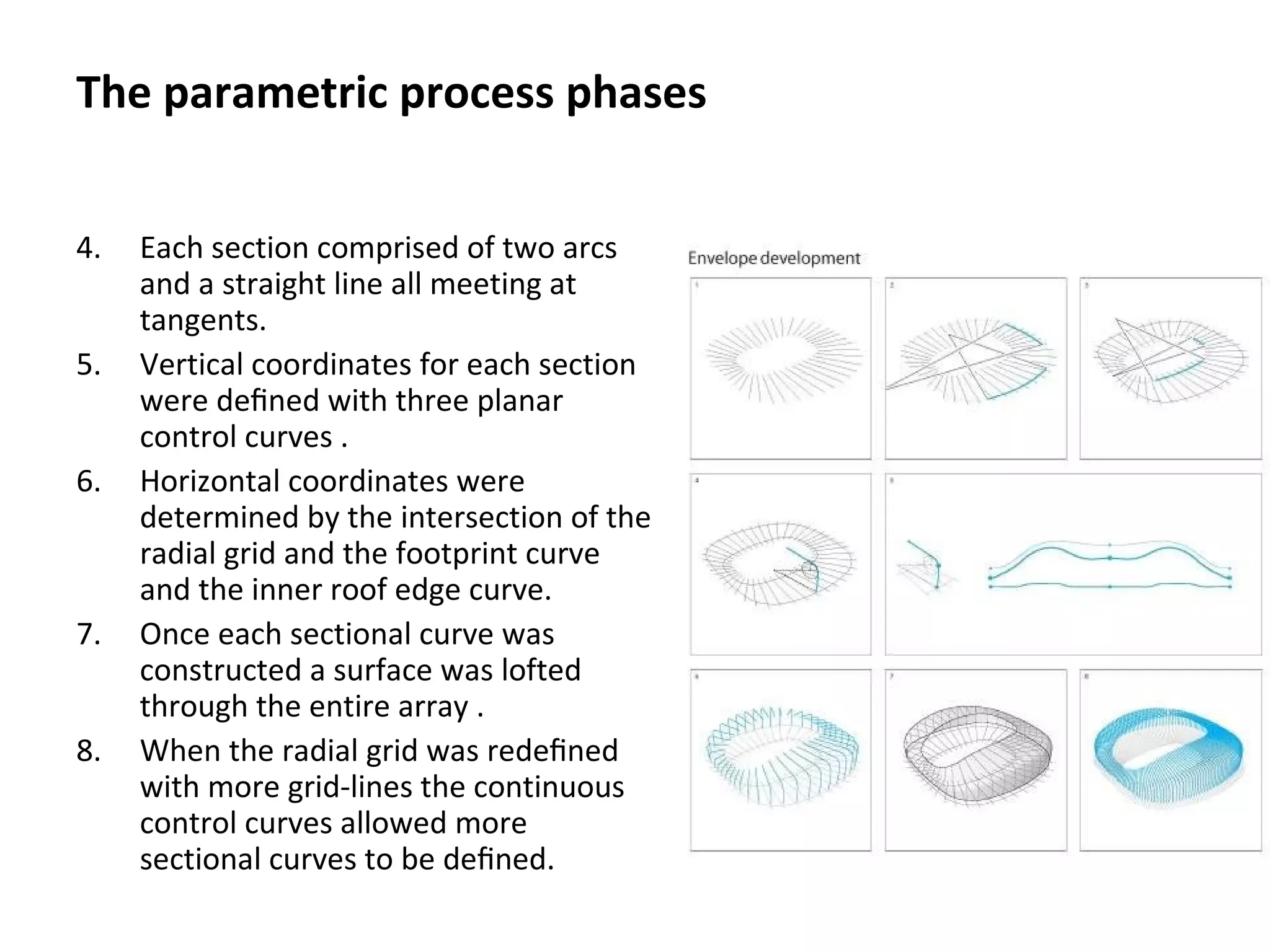
This document summarizes Roland Hudson's 2010 PhD thesis on strategies for parametric design in architecture. The thesis includes an introduction to parametric design and case studies examining three major projects: Foster and Partners' Elephant House, Foster and Partners' Gherkin building, and HOK's Lansdowne Road Stadium. For each case study, the document outlines the key design challenges, how parametric modeling was used to address these challenges, and the different rationalization approaches taken during the design process.
call girls in Kamla Market (DELHI) š >ą¼9953330565š genuine Escort Service šāļøāļø
Ā
Parametric design
1. Strategies for parametric design in
architecture.
An application of practice led research.
Roland Hudson
A thesis submitted for the degree of
Doctor of Philosophy
University of Bath Department of
Architecture and Civil Engineering
2010
Presented by :-
Dania Abdel-Aziz
Dua'a Ma'ani
2. Simplified structure of the dissertation
1. Introduction
ā¢ What is parametric design?
ā¢ Considerations
ā¢ Methodology
2. Design theory background
3. Design theory specifics
4. State of practice
5. Introduction to the case studies
ā¢ Lansdowne Road Stadium
ā¢ Stadium Seating Bowl Modeller
ā¢ Further case studies
6. Conclusions
3. Structure of the presentation
1. Introduction
2. Terminologies
2.1. What is parameter
2.2. What is parametric design
3. Rationalization
3.1. Post-realization
3.2. Pre realization
4. Case studies
4.1. Elephant house- Foster and partners
4.2. Mary Axe tower- Foster and partners
4.3. Lansdowne Road Stadium- HOK
5. Parametric model videos
6. Summary
4. Terminologies
2.1.Definitions of Parameter:
According to the Webster dictionary:
a : an arbitrary constant whose value characterizes a member
of a system (as a family of curves); also : a quantity (as a
mean or variance) that describes a statistical population.
b : an independent variable used to express the coordinates of
a variable point and functions of them ā compare.
c :any of a set of physical properties whose values determine
the characteristics or behavior of something.
d: something represented by a parameter : a characteristic
element; broadly : CHARACTERISTIC, ELEMENT, FACTOR.
5. Terminologies
2.1.Definitions of Parameter:
According to Wikipedia :
Origin of the word : (from Greek , "para", meaning "besideā,
and "metron", meaning "measure") .
In its common meaning, the term is used to identify a
characteristic, a feature, a measurable factor that can help
in defining a particular system. A parameter is an
important element to take into consideration for the
evaluation or for the comprehension of an event, a project
or any situation.
6. According to Britannica encyclopedia:
parameter, in mathematics, a variable for which the range of possible values
identifies a collection of distinct cases in a problem. Any equation
expressed in terms of parameters is a parametric equation. The general
equation of a straight line in slope-intercept form, y = mx + b, in
which m and b are parameters, is an example of a parametric equation.
Terminologies
7. 2.Definitions of Parametric:
āParametricā is a derivative of āparameterā which itself originates
from the greek para, meaning a subsidiary or beside and
metron, as in to measure (OED, 2002). In mathematics a
parameter is deļ¬ned as āa quantity constant in the case
considered but varying in different casesā.
Terminologies
8. 3.Definitions of Parametric Design:
Design is a task that involves deļ¬ning a description of a problem, then
generating and searching amongst alternatives to ļ¬nd a solution that
satisļ¬es the problem. āParameterā has been deļ¬ned as any
measurable factor that deļ¬nes a system or determines its limits.
āParametric designā is understood as a process where a description of a
problem is created using variables. By changing these variables a range
of alternative solutions can be created, then based on some criteria a
ļ¬nal solution selected.
Conclusion : On this basis it could be said all design is parametric.
Terminologies
9. Parametric design in this book:
The process of developing a computer model or description of a design
problem.
This representation is based on relationships between objects controlled by
variables. Making changes to the variables results in alternative models.
Selection of a solution is then based on some criteria which may be
related to performance, ease of construction, budget requirements, user
needs, aesthetics or a combination of these.
Strategies for parametric design in architecture, by:
Roland Hudson.
10. Methodology :
Three possible research approaches are described;
ā¢ The ļ¬rst is a review and use of literature originating from practice.
ā¢ The second is the use of case studies.
ā¢ Thirdly the use of laboratory type experiments with designers.
Only the ļ¬rst two of these approaches are used in this thesis and will be
explained here.
Strategies for parametric design in architecture, by:
Roland Hudson.
11. Case studies :
1. The elephant house.
2. Mary axe tower.
3. Lansdowne Road Stadium.
The 3 types of Rationalization:
1.Rationalization is the application of known geometric principles
and construction techniques in order to realize a project.
2.Post-rational is where geometry and construction constraints are
considered after a conceptual design phase (Whitehead &
Peters, 2008).
3.Pre-rational is when geometric method is rational from early
design stages.
Case Studies
12. Post-rational
ā¢ Foster and Partnerās Elephant House began as free-form surfaces
but project budgets and architectural criteria demanded planar
quadrilateral mesh solutions. The task for the Specialist Modeling
Group (SMG) is to ļ¬nd a geometric rationale that would best ļ¬t
the original forms.
Foster and Partners choose to use simple arc-based geometric
compositions for their ease of communication and subsequent
reduction of error (Whitehead, 2003).
Matching original geometry with rationalized geometry and testing
how well this matches is a major part of the design process.
Conclusion2: Rationalization is concerned with ļ¬nding a
construction solutions that cover a range of parametrically
generated details using straight bars and ļ¬at sheets. This process
Case study:
The Elephant house
14. The Elephant house
Copenhagen's New Elephant House is
set within a historic park and
seeks to create a visual
relationship between the zoo and
the park.
The New Elephant House brings a
sense of light and openness to a
building type traditionally
characterized as closed.
Covering the building with two
lightweight, glazed domes, which
maintain a strong visual
connection to the sky and the
changing patterns of daylight.
15. The elephants can congregate under
these glazed domes, or out in the
connecting paddocks.
In the wild, the bull elephants have a
tendency to roam away from the
main herd.
The plan form is therefore organized
around two separate enclosures,
a large one for the main herd,
and a smaller one for the more
aggressive bull elephants.
The Elephant house
16. The building is dug into the site, to
minimize its visual impact in the
landscape and to optimize its
passive thermal performance.
For visitors, a ramped promenade
leads down through the building
looking into the elephant
enclosures along the way.
The torus, a mathematical form, was
used to "harness the complexity"
of the design. The structural and
glazing logic was related to the
logic of the torus.
The Elephant house
17. This geometric set-out and
constructional logic was
encoded into a parametric
computer model.
The parametric model allowed for
the generation and
exploration of many different
design options.
The Elephant house
18. As the design was expressed as a series of relationships and the computer
model could be updated instantaneously, the design could remain quite
fluid until very late in the design process.
The environmental strategy was expressed both through a series of opening
panels and a varying fritting pattern on the glazing panels of the canopy.
The design of this system - the distribution of the different panel types and
the creation of the custom fritting patterns - was explored using computer
programming.
A design emerged that incorporated a semi-random placement of leaf
textures. This created an environment with different light levels allowing
the elephants to find a spot comfortable to them.
The Elephant house
19. Pre-rational
The Specialist Modeling Group (SMG) considers pre-rational approaches to
be where the geometric system and means of communicating to the
contractors are clearly deļ¬ned early in the design stages. The construction
system may not be clearly deļ¬ned initially but rational geometry that
involves planar panels leads to a feasible solution. St. Mary Axe is
described as pre-rational which meant a parametric model could be
developed that allowed sharing therational geometry, which in turn
simpliļ¬ed detailed design, fabrication and construction (Whitehead &
Peters, 2008).
Case study:
The Gherkin project ( Mary axe tower)
20. The Gherkin project ( Mary axe tower)
The Gherkin is one of the projects
the Specialist Modeling Group
(SMG) was involved with and is a
prime example of how geometry
was chosen to satisfy constraints.
Going by the official name of 30 St
Mary Axe, the building is 180
meters tall, three times the
height of the Niagara Falls.
21. The Gherkin project ( Mary axe tower)
There are three main features that
make it stand out from most
other sky-scrapers:
ā¢ it's round rather than square,
ā¢ it bulges in the middle and tapers
to a thin end towards the top,
ā¢ and it's based on a spiraling
design.
All these could easily be taken as
purely aesthetic features, yet
they all cater to specific
constraints.
22. Surfaces that can be described by
mathematical equations ā such as slices
of cones, tori, or spheres ā often form
the basis of the Specialist Modeling
Group's (SMG) design.
This is advantageous when it comes to
creating virtual models, as
mathematically generated surfaces are
easily represented on a computer.
Rather than describing a structure by a
large number of individually stored co-
ordinates, you only need to store an
equation.
The Gherkin project ( Mary axe tower)
23. The exact shape of the surface can be controlled by varying the parameters in
the equation (see the figure below for an example).
Flat panel solutions can then also be modeled with relative ease: the
software simply has to draw straight line segments between a collection
of node points on the original surface.
Description of photo 4 : These surface are the graphs of the function z=e-
a(x2+y2). Here the 3-dimensional co-ordinate system is formed by the x, y
and z axes, with z being the vertical axis The number a determines the
shape of the surface. The first surface has a=1, the second a=5
The Gherkin project (Mary axe tower)
26. How this case study contributes to the understanding of the role of the
parametric designer;
ā¢ Early design stage application of parametric methods to develop a
problem description (the point at which parametric design is applied).
ā¢ Use of a parametric definition shared between architects and engineers.
ā¢ The project also provides further practical examples of parametric tasks
such as translation, fragmentation of control system, fragmentation of
problem, use of multiple representations and defining initial parameters.
ā¢ It defines a new parametric task; by involving an architectural parametric
designer in the detail design phase of the project.
Lansdowne Road Stadium (LRS)
It has been renamed to āAVIVA Stadiumā
27. Lansdowne Road Stadium
The key objective of the project was to
design co-ordinate and deliver an
organic shaped 50,000 seat stadium
within the bounds of the site of
Lansdowne Road.
This was achieved through developing
a series of parametric based
Generative Components models to
drive the design from initial form /
shape development through to
production and construction
information.
28. Context
The stadium site was highly constrained, with tight boundaries to the
north and south formed by low rise residential buildings.
Lansdowne Road Stadium
29. Context
The stadium site was highly constrained;
1. with tight boundaries to the north
and south formed by low rise
residential buildings.
2. Expansion to the west was limited by
the retained rail link and to the east
by the grounds of a local rugby club.
3. Inside the stadium resisting these
external forces was a requirement
for a seating capacity of 50,000.
Lansdowne Road Stadium
30. Context
4. Exhaustive daylight studies deļ¬ned the
position of the inner roof edge to
provide adequate natural light to
ensure a healthy grass pitch growth.
The design submitted for planning
approval proposed a form resulting
from a combination of pressures from
all these constraints. Although not
initiated in a parametric way, the
underlying geometric considerations
for the early design were rule driven.
Lansdowne Road Stadium
31. Overview of the completed parametric model
The parametric process can be described in four distinct phases:
1. At the root of the process is the geometric definition of the envelope
geometry, which was the responsibility of the architects. This formed the
basis of the design of the structural system and the facade.
2. Structural design was undertaken by BH and the facade design remained
the responsibility of HOK. Construction documentation of the facade was
developed parametrically.
32. Overview of the completed parametric model
The parametric process can be described in four distinct phases:
3. FaƧade information was issued to specialist cladding designers, William
Cox and Clad Engineering (WC+CE) who developed detailed design for
manufacture.
4. The detail design phase was supported with a series of parametric models
developed by HOK. Detail design proposals by WC+CE were checked by
integrating them into the initial parametric models.
33. 1. Envelope geometry
Architectural modeling of the stadium envelope geometry consisted of three
components;
1. numerical parameters,
2. static geometry files,
3. and a Generative Components (GC) script file.
The parameters, or numeric data, were stored in an Excel spreadsheet, and
were read into GC as the script file was executed. Static geometry was
also referenced in from CAD files. From this initial data and rules defined
in the script file, a graphical control system was constructed which
defined the configuration of the stadium geometry.
The parametric process phases
34. The parametric process phases
1. Envelope geometry
Architectural modeling of the stadium
envelope geometry are explained as
following:
1. The ļ¬rst step in the geometry
construction sequence was to import
the CAD ļ¬le that deļ¬ned a radial grid
that corresponded with structure of
the roof.
2. Eight parametrically controlled
tangential arcs deļ¬ned the footprint
of the stadium .
3. The same system was used to deļ¬ne
the inner edge of the roof . The
intersection of the footprint and the
radial grid deļ¬ned the origin of each
sectional curve .
35. 4. Each section comprised of two arcs
and a straight line all meeting at
tangents.
5. Vertical coordinates for each section
were deļ¬ned with three planar
control curves .
6. Horizontal coordinates were
determined by the intersection of the
radial grid and the footprint curve
and the inner roof edge curve.
7. Once each sectional curve was
constructed a surface was lofted
through the entire array .
8. When the radial grid was redeļ¬ned
with more grid-lines the continuous
control curves allowed more
sectional curves to be deļ¬ned.
The parametric process phases
36. 2.Structural design
The parametric envelope geometry was deļ¬ned with sections arranged
radially, these were the starting point for the parametric structural model.
The parametric process phases
37. The radial section curves represented the interface between the architectural
and structural design.
The parametric process phases
38. Using the sight lines from the last row of seating, bending moments and
transportation constraints, a series of geometric rules were deļ¬ned.
These rules generated a centre line model of structural members.
The parametric process phases
39. 3.Cladding design
The starting point for the cladding design was
also the radial array of sections that deļ¬ne
the envelope geometry. Intermediate
sections were required to deļ¬ne mullions
which supported the cladding between
structural bays. Each structural bay was
divide by three,four or ļ¬ve depending on
the bay size. The cladding system was
designed as a rain screen consisting of
inter-locking louvres. Panels were planar
and made from folded polycarbonate
sheets, all panels used the same proļ¬le but
varied in length. A lateral axis of rotation
allowed panels to be ļ¬xed in a range of
positions between open and closed.
The parametric process phases
40. This allowed sections of the facade to be
open to allow air intake and exhaust for
air handling units positioned behind the
facade. The polycarbonate panel was
ļ¬xed onto an axle along its own lateral
axis. This axle was supported at either
end by a bracket which was connected
to a mullion. The brackets had two axes
of rotation, the angles for each were
deļ¬ned by the positions of neighboring
panels.
The parametric process phases
48. Construction documentation
The parametric modeling of the facade cladding system required all the
parameters for configuring rotation angles of panels and brackets and
spacing along mullions to be calculated. This numeric information was
extracted from the model and recorded in spreadsheets. Together with
geometric models, this information was required as part of the
construction documentation package.
49. Detail design
In order to support the detail cladding design phase, they produced several,
quickly constructed parametric models. These were used to determine
ranges of angular and dimensional differences that the generic
connections needed to accommodate.
50. Detail design
Other models were developed to
check for clashes between
the facade panel brackets and
the connection between mullion
and floor slab.
Parametric modeling included a
rationalized acoustic paneling
system.
54. Parametric modeling of the entire facade provided a means for checking that
HOKās proposed cladding system would work correctly all round the
stadium and this ensured a high level of architectural control of the
system. The parametric model was also used to produce geometry ļ¬les
for three-dimensional visualization both in computer generated graphics
and physical models .
The parametric process phases