Design For Accessibility: Getting it right from the start
Ans ys fatiga
1. Fatigue Analysis of a Welded Assembly Using ANSYS
Workbench Environment
Klaus-Dieter Schoenborn
ANSYS Service @ CADFEM GmbH, Germany
Abstract
Fatigue analysis of welded joints often requires the handling of large structures, since typical weld seams
are small details in large assemblies. FE models deduced from the global structure require idealization and
are not well suited for fatigue concepts that are based on the local stress state. The model of the global
structure is used to locate hot spots and to transfer the applied loads to a local deformation. The analysis
concepts proposed by the IIW and other organizations require a very detailed and specific representation of
the welded joints. ANSYS Workbench preprocessing capabilities combined with ANSYS submodeling
technology allow demonstrating a fast and reliable workflow. The ANSYS Workbench Fatigue tool
performs the high cycle fatigue life calculation.
Introduction
Over the last decades, numerous concepts have evolved for Fatigue analysis of welded assemblies. The
traditional approach is to analyze the fatigue life based on the nominal stress concept. This concept derives
the stress state at the weld seam according to a beam theory approach. The Forces and Moments acting on a
certain cross section are divided by the section properties to yield the nominal membrane and bending
stress. This approach however is limited. The stress state is defined according to a nominal cross section
and the fatigue properties are taken from tabulated geometric constellations, the FAT classes. Complicated
geometries often do not allow defining a nominal cross section and the stress state is often not just a pure
combination of membrane and bending stress. Also, the geometric constellation of the structure might not
fit into one of the FAT classes. In the recent years, other concepts have been developed to address those
limitations.
The extrapolation concept proposed by the IIW and other institutes derives the stress state from a numerical
FE stress result and thus eliminates the need to define a nominal cross section. The stress is evaluated at
certain distances away from the weld and then extrapolated towards the critical spot. Thus there is no need
to model the weld seam itself. The evaluated stress state is not limited to membrane and bending stress. The
IIW approach is well proven and supported by a large amount of test data, thus being widely accepted in
the industry and by the certification authorities. However, the preprocessing effort imposed on the analyst
to follow those concepts may be quite substantial, since they require a very distinct type of Shell or Solid
modeling.
The effective notch stress concept offers a different approach to analyze the stress state at the weld seam.
This concept is based on a volumetric representation of the weld seam geometry. The representation differs
among concepts, the most prominent being the R1MS concept. The process starting from CAD Geometry
to the determination of fatigue life requires extensive preprocessing and computing resources. The required
number of DOF may largely exceed those for the nominal stress or the extrapolation concept, but it offers a
quick and comprehensible workflow to the analyst.
Submodeling – The analysis concept to cope with large
structures
Structural analysts that are doing fatigue calculations on large structures have always faced the problem of
FE models that grow beyond any reasonable DOF limit. This is due to the fact that the global model
stiffness has to be reflected to a certain level of accuracy. The accuracy of the global deformation state
affects the local stress state and thus largely influences the accuracy of fatigue life prediction. The accuracy
of the local stress state itself crucially depends on the local mesh density, which is imposing tough
2. constraints on the maximum element edge length and in consequence to the model DOF number. To cope
with this problem, ANSYS has developed the submodeling technique as an advanced analysis method to
separate the global deformation analysis from the local stress analysis. This concept requires two separate
models. The full model represents the global structure and is used to transform global loads to local
deformation. The submodel represents the local geometric details with an appropriate mesh density. The
submodeling algorithm then interpolates the deformation from the global model to the submodel
boundaries and solves for the local stress state. This method works well for linear static analysis and gives
reliable results, but it requires extensive planning and documentation of the workflow, especially if many
submodels and numerous load cases are involved. Also, the setup of a submodel may take a considerable
amount of time. The submodeling technique naturally requires some interaction with the CAD data, since
the critical spots within the structure are unknown to the analyst prior to solving the full model and
analyzing the global results.
ANSYS Workbench offers a very efficient way of CAD interaction, handling and documenting all data
involved in the analysis. With small APDL enhancements applied to the model tree, the ANSYS
submodeling technique may be combined with the Workbench Geometry handling and process
documentation. Thus, a workflow can be presented that covers the whole process from CAD to fatigue
analysis. The analysis may be performed in 6 steps:
1. Import the model from CAD and defeature using Design Modeler
2. Apply the global loads and solve the global model, identify critical spots using Design Simulation
3. Generate one or more Submodels from original CAD Geometry using Design Simulation
4. Mesh the Submodel, Interpolate the deformation to the cut boundary and solve using Design
Simulation
5. Get the fatigue life according to the R1MS FAT Class using the Fatigue Tool from Design
Simulation.
6. Evaluate other sets of loads, modify the design, modify the type or number of welds – Design
Modeler – Design Simulation
The Key strengths of ANSYS Workbench are its abilities in geometry handling and its robust meshing
technology. Since all Workbench concepts and methods, e.g. the method for applying structural loads, are
based on the Topology of the CAD model and not on its FE representation, Workbench conflicts with the
established extrapolation concepts. Those concepts require the FE Solution to be evaluated at certain node
positions. For fatigue analysis of welded assemblies inside Workbench, a concept has to be chosen that
does not require control of the node and element locations around the hot spot. The effective notch stress
concept is a natural choice for this approach, since it is based on the CAD Topology and not on the FE
representation.
The R1MS concept – fatigue analysis using the effective notch
stress from finite element results
FE models without a representation of weld seams naturally do not allow for a direct readout of the hot spot
stress at the weld seam. If the model is made up from shell elements, the stress state may be evaluated at
some distance from the seam and extrapolated. If the model is made up from solids, the missing
representation leads to singular stress states and thus to infinite stresses. In order to allow a direct readout
of the stress state at the hot spot, a general modeling concept has been developed to assure a non-singular
stress state. The R1MS concept represents the weld seam geometry for fillet welds with a chamfer. The
chamfer is dimensioned according to the value of the characteristic length “a”, which is taken from the
construction data. The “a” is the height of an even sided triangle inscribed by the fillet weld. The transition
edge between the chamfer and the surrounding material is smoothed with a radius of 1 mm. Figure 1 shows
an example model for the R1MS concept.
3. Figure 1. Sample model with fillet weld model according to the R1MS concept
With this model the singularity is removed from the stress solution and the stress state now may be
evaluated directly from the FE solution. Naturally, an effective notch stress concept imposes tight
constraints on the element size to minimize the discretization error. The R1MS concept recommends using
at least 10 Elements on the 1 mm radius arc to achieve reliable stress results. The resulting stress is
correlated to the expected life by means of a fictitious “weld seam” material. The material data is based on
the result of a large quantity of fatigue test results on different geometry configurations. It consists of a log
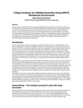
stress - log N curve, called the FAT 225 class [2]. The value of 225 refers to a 5% failure probability at 2
million cycles when the notch stress is equal to 225 Mpa. Figure 2 shows the log N – log stress curve for
FAT 225. Any mean stress that might be present is ignored, since the fatigue test results showed that a
positive mean stress does not have a high impact on the fatigue life. This is due to the fact that the
components are usually sharp notched and high residual stresses reside in the material adjacent to the weld
seam.
10 N/mm²
100 N/mm²
1000 N/mm²
1.E+05 1.E+06 1.E+07 1.E+08 1.E+09
log (N)
FAT225
Figure 2. FAT 225 log N – log stress curve used for the R1MS Concept.
4. With respect to Workbench, this curve may be introduced as a new set of material data in the engineering
data tab and used as a basis for fatigue life calculation in the fatigue module (Figure 13).
Sample analysis: fatigue analysis of a tubular welded assembly
This chapter illustrates the proposed workflow on a typical welded assembly that would be difficult to
analyze with a conventional nominal stress approach.
Step 1:build / Import the model from CAD
Figure 3 shows a sample model that has been created using Design Modeler as a CAD program. The
structure is a curved tubular assembly with a regular pattern of joints. It represents a small sample section
of a repetitive structure that forms the track of a rollercoaster. The curvature of the tubes causes some
deviation from a pure bending and membrane stress state in the tube sections when loaded with a service
load like the one shown in Figure 4. The loading on this structure is caused by a trolley rolling along the 2
upside tubes. It is transferred to the larger tube via the joint elements and passed to the supporting structure
(not shown). The loading is generated by a combination of gravity and centrifugal forces.
It is difficult to define a nominal cross section for the application of a nominal stress concept for the weld
seams. The stress state in curved beams is not a pure membrane and bending stress state. Therefore, the
application of the nominal stress concept is questionable. Applicable concepts are the extrapolation concept
and the effective notch stress concept.
Figure 3. CAD Model of a curved tubular assembly – full model.
5. Figure 4. Typical loading of the assembly – combined inertia and gravity loading.
Step 2 mesh and solve the global model
For the FE Model setup of the global model, the analyst may choose from 3 alternatives, regardless of the
concept that is envisaged:
1. Create midsurfaces from the solid model and mesh the midsurfaces with shell elements.
2. Modify the CAD geometry with Boolean operations to achieve a structured mesh and form a
single solid part in Design Modeler. Create a solid hexahedron mesh.
3. Do not modify the geometry at all. Mesh the model with Tetrahedrons and model the joints with
surface-to-surface contact.
Alternative 1 requires extensive resources to be spent on the CAD model. Midsurfacing is still not an
automated process and requires a lot of user interaction. The geometric representation of the structure may
also suffer from a certain amount of loss in accuracy. Shell modeling should be chosen on very large and
thin walled assemblies and may often be the only way to proceed on large assemblies.
Alternative 2 requires less user interaction, but still takes a considerable amount of resources that have to
be spent on the CAD side. Since today’s CAD geometry engines are very robust with regard to Boolean
operations, this approach should be chosen in most cases where the geometry will allow sweep operations
for meshing. The model may be meshed as a single part or as a contact assembly. Since submodeling is
envisaged, contact surfaces in the vicinity of the cut boundary should always be avoided.
Alternative 3 does not require any user interaction. This approach should be preferred since it is most
effective. It is only limited by element aspect ratios on thin walled structures and the number of DOF that
can be handled.
The solution derived from alternative 3 proved to work well in most cases without spending any time on
the CAD model. The Submodeling algorithm works well if the regular prerequisites for submodeling are
obeyed [1]. Contact pairs may be part of the interpolated region in the full model. As long as they are
completely enclosed by the submodel cut boundary. Figure 5 shows a sample mesh with surface-to-surface
contact.
6. Figure 5. Mesh with Contact for the global model
Step 3: analyze the global model results and identify critical spots
The full model gives a general impression on the structural deflection. The structural result is saved and
maintained in an RST file on the Hard disk drive. The global solution is needed for interpolation of the
submodel boundary conditions. It is also used to find the location of critical spots in the structure.
Evaluation of the global stress state will not lead to a reliable location, since the solution has a lot of
singular stresses and therefore the local mesh density drives the local stress. Therefore, looking at the stress
value is not an effective method. Workbench now offers a graphical representation of the sum of nodal
forces that is transferred through a contact interface. A sample of this plot is shown in Figure 6. This plot is
easy to interpret and offers a reliable way of determining critical locations.
Figure 6. Plot of the contact forces in ANSYS Simulation
7. Step 4 Generate the submodel from CAD data and mesh
Once the critical spots are known, submodels may be created from CAD data using Design Modeler or a
similar CAD program. This is done by simply cutting the model and suppressing the remaining solids. This
process automatically achieves geometrical consistency, since the remaining solid does not change its
reference with respect to the global coordinate system. Since the interpolation is done with reference to this
system, submodeling crucially depends on this geometric consistency. Before the submodel is transferred to
Design Simulation, it has to be modified according to the modeling concept chosen. Figure 7 shows a
submodel that has been modified to suit the R1MS concept. Fillet welds have been added according to the
drawings and a radius of 1 mm has been added along the chamfer edges.
Figure 7: Submodel geometry of a critical structural detail. Weld seam modeling is done
according to the R1MS concept
Figure 8:Submodel mesh used for the location of critical spots inside the submodel.
8. The submodel is inserted as a separate branch in the project tree below the global model and meshed with
default mesh settings (see Figure 8), This intermediate step is taken to analyze the local stress state since
the critical spot inside the submodel is still unknown.
Figure 9. Submodel mesh detail using the sphere of influence feature in DS.
Step 5: Interpolate the boundary conditions from the global model to
the submodel and solve
The interpolation is done by inserting a small macro into the environment branch of the submodel tree like
shown in Figure 10. This macro clears the database, resumes the full model from the RST file and performs
the interpolation in /post1 (CBDOF command). After that, the submodel is restored, the interpolated
boundary conditions are read and the submodel is solved.
ANSYS Workbench Design Simulation solves the model and performs post processing like on any regular
model. From the interpretation of the resulting local stress state in the submodel, the critical locations may
now be determined. Still, the discretization is much too coarse to accurately predict the fatigue life from the
resulting stress. The R1MS recommendation is to use at least 10 elements in the 1 mm arc, resulting in an
element edge length of less than 0.1 mm. So, a locally refined mesh is needed to proceed with the life
calculation. The “sphere of influence” method of Workbench is ideally suited for the requested type of
mesh. Figure 9 shows the refined mesh on the submodel.
Step 5 is now repeated simply by creating the “sphere of influence” tab on the mesh branch and solve. The
interpolation is now performed on the new FE mesh, since the macro overwrites any files that where
created on a previous run. The interpolation is done from the original RST file, which still resides in the
working directory.
9. Figure 10. project tree showing the Macros used for submodeling
Step 6: analyze the submodel solution and calculate the fatigue life
The effective notch stress may now be read from the submodel and compared against the FAT 225 material
data. The useable life calculation may be done by inserting a Simulation fatigue tool into the submodel
branch.
Analysis Results & Discussion
Key strengths of the method:
Model consistency is maintained by using Design modeler to create submodels based on the original CAD
Geometry. Correct position with reference to the CAD coordinate system is automatically assured and may
be checked by displaying the submodel as part of the global model.
The full FE model to determine the deformation field has to be run only once. An arbitrary number of
Submodels may be created and solved by interpolation from one single run of the global structure.
All Submodels may be included in the model tree. Variants may be studied without having to repeat the
whole process. Submodels may be altered thanks to the bidirectional CAD interface to Design Modeler or
other CAD Programs.
The submodeling technique allows comparing different effective notch stress concepts with little additional
effort to judge the reliability of the fatigue life prediction.
Design variants including the submodeling process may be studied without much additional work, since the
process structure is maintained within the Workbench model tree.
Conclusion
ANSYS Workbench offers an effective way to determine the useful life of large welded assemblies The
combination of Workbench Geometry handling and meshing capabilities, the ANSYS Submodeling
10. algorithm and the R1MS effective notch stress concept form a quick, robust and accurate method for
fatigue analysis on large 3 dimensional structures.
Figure 11. resulting v.Mises Stress on the Submodel in Design Simulation
Figure 12. Stress intensity on the submodel at the critical spot.
11. Figure 13. Log N log stress curve of FAT225 in Design Simulation
Figure 14. Useable life of approx. 114.000 cycles calculated with the Design simulation
fatigue tool
12. References
[1] ANSYS advanced analysis techniques guide – Chapter 9 – submodeling
[2] European Standard prEN 1993-1-9 EUROCODE 3 – Design of steel structures Part 1.9 Fatigue
[3] International Institute of Welding IIW document XIII-1965-03 / XV-1127-03 – Recommendations
for fatigue design of welded joints and components, A. Hobbacher, University of applied sciences,
Wilhelmshaven