SlideShare a Scribd company logo
1 of 7
Download to read offline
How to deal with the annoying Hot Spots in FEA
Jon Svenninggaard
Department of Mechanical Engineering
VIA University College, Denmark
February 20, 2017
1 Introduction
Often, when I talk to fellow engineers one of the most common question I
hear is; How do we deal with the annoying ”Hot Spots” in our solid structure
Finite Element Analysis (FEA) and how do we justify the stresses in those areas?
A ”Hot Spot” is in this context a geometric singularity where high stresses
are confined to a small area. This area stands out as it mostly represents stresses
that exceed the allowable. The singularity may come from boundary conditions
where the transition between stiffness is high, it may come from contact prob-
lems, it may arise from sharp edges where the high stressed area is confined to
the elements near the corner, or it can emerge from discretization error of the
mesh. The mesh generation typically results in that most fillets in the 3D CAD
(Computer Aided Design) model, is simplified as perfectly sharp corners. We
all know that perfectly sharp corners and infinite stiff structures do not exist in
real life. The first two problems are exemplified in Fig. 1. Here, the first image
shows the boundary conditions. The bracket is fixed on the upper surface and a
load of 1000 N is applied at the other end. Initially, using an element size of 10
mm and 8-noded solid elements with 24 degree of freedom (DOF), the stresses
are shown in the middle image. After a mesh refinement, the stresses in the
inside corner increase and would increase even further by additional mesh re-
finements. Furthermore, it can be seen that there is an increased stress near the
edges where the fixed support is located. So, can we just disregard these areas
where the stresses are high or do we need to change the geometry, boundary
conditions or use a completely different approach?
Initially, we need to understand that most Finite Element Analysis is per-
formed as linear elastic. This means that the displacements, stresses and strains
are doubled if the load is doubled. I.e. there is a clear linear correlation between
those field quantities. This does not relate to the real world where the stress -
1
Figure 1: A random bracket is loaded with 1000 N on the right end and fixed on the upper surface.
The middle image shows the unaveraged first principal stress with an element size of 10 mm. The
third image displays increased stress at the corner with an element size of 5 mm.
strain relationship in most ductile metallic materials is only linearly related until
a certain point. After this, yielding and plasticity are the governing parameters
and the linear force - displacement relationship is no longer valid. Thus, when
we see stresses that are far beyond the ultimate limit strength, often this is not
the entire truth and a singularity or ”Hot Spot” may be present. Moreover,
sharp corners in real life are always rounded. Even if it cannot be seen by the
naked eye it will seem rounded if observed through a microscope. This even ap-
plies for most sharp cracks. However, even if smaller loads are applied to very
sharp corners or cracks, the geometry alters due to crack tip localized plasticity
and the stresses distribute as if the corner was rounded. Nonetheless, it is highly
important to estimate the strain or stress condition at these locations correctly
if fatigue loading is involved. If fatigue loading is involved, the plastic strain-
ing due to the presence of sharp corners can easily lead to the formation and
propagation of cracks, which ultimately could lead to a complete loss of bearing
capacity in the structure. This also applies if static loadings are involved as the
stress concentration factor could lead to stresses above the ultimate limit stress
of the material and a sudden rupture might occur.
2
2 How to deal with it?
The first thing to consider when a ”Hot Spot” is observed is obviously to carry
out a mesh convergence study. This would give the engineer information about
the stress gradient in the area, and if appropriate elements and element sizes
have been used! One method is to utilize one of several adaptive meshing tech-
niques; These are the p-refinement technique that changes the polynomial or-
der of the element. The r-refinement technique that relocates elements and the
mesh. Or the h-refinement technique that refines the mesh in areas of high stress
gradients. Even combinations hereof exists as for example the hp-refinement
technique. Some of these techniques are usually build into commercial finite
element software packages. The h-refinement and p-refinement techniques uti-
lizes the posteriori Zienkiewicz - Zhu (ZZ) error estimate [1] that is determined
as:
||U||2
=
m
i=1
{ }
T
i [E] { }idV (1)
Here, m is the number of elements in the structure or area of interest, [E]
is the constitutive matrix and { } is the strain vector. The global energy error
norm in the structure is determined as:
||e||2
=
m
i=1
({ ∗
}i − { }i)
T
[E] ({ ∗
}i − { }i)dV (2)
Here, { ∗
} represents the smoothed strain field over the entire structure.
Thus, the global energy error norm gives a measure of the variation of energy
within the structure. This is then utilized to find the relative error in the
structure as:
η =
||e||2
||U||2 + ||e||2
1/2
(3)
This relative error η, can take values in the range; 0 > η > 1. Consequently,
a good discretization is usually obtained with η ≤ 0.05. For the case of the
h-refinement technique this is illustrated in Fig. 2. Here, the plate is loaded by
an evenly distributed load on the top edge and fixed along the edge A-B. Using
adaptive meshing with the h-refinement technique, the mesh is refined around
the corners. With increasing mesh density, the stress at these points will tend
towards infinity. Already after the first mesh revision, the engineer would realize
that he or she instead, should consider changing the boundary conditions, or
simply disregard these areas from the stress analysis.
The example illustrated in Fig. 2, is further visualized in Fig. 3. Using the
commercial software Ansys Workbench, the difference between the left boundary
being completely fixed and it being subjected to a different boundary condition
is easily seen. The analysis shown in Fig. 3 a) to c) never converges! The mesh
3
Initial mesh with linear
strain triangles LST
A
B
q
First revision of the mesh
using adaptive meshing with
the h - method
Second revision of the mesh
using adaptive meshing with
the h - method
A
B
q
A
B
q
y
x
Figure 2: Results from adaptive meshing of a 2D plate subjected to plane stress. The plate is
completely fixed on the edge A-B. Each mesh revision aimed at η = 0.05. (Freely inspired from [1])
density is increased in the corners by each iteration and the stress increases. In
Fig. 3 d) and e). The analysis converges with within a few iteration. This is
illustrated in f). The relative error η in the model cannot directly be plotted,
but it can be scripted quite easily in most FE packages.
a) b) c)
d) e) f)
Figure 3: 2D Analysis of plate loaded with a distributed load of 5 MPa on the top edge. Sub figures
a) to c) shows the effect, when the entire left boundary is fixed. Sub figures d) and e) shows
the effect of the upper and lower left boundary edge being locked in the horizontal direction. The
middle left segment is locked in both horizontal and vertical direction. Sub figure f) shows the
convergence curve for d) and e).
If we turn our attention towards other methods and approaches, a lot of work
has been committed to finding methods to deal with weld details and relating
them to a certain Fatigue class (FAT) using the FEM. Most used is probably the
”Nominal stress method” which relates a number of structural details to certain
4
fatigue classes or SN - curves. The method has among others been adopted by
Eurocode 3, part 1-9, [2] and a series of other 3rd
party organizations. This
method however, is not directly usable for the above discussed singularities as
no listed structural details exists to quantify the various singularities that may
emerge in the FEA.
A more specialized method that has been standardized by the International
Institute of Welding [3] and DNV [4] is the ”Structural Hot Spot method”. This
method can be used either with physically mounted strain gauges or the Finite
element method. The method is based on that strains or stresses are evaluated
at certain distances from the weld toe and extrapolated here to. Then, the stress
or strain level of the detail is compared to a certain FAT class. This method
can prove quite handy for shell models. For shell models, the stress at sharp
corners or transitions between profiles or plates, can be evaluated by extrapo-
lating stresses into the corner. Thereby the ”Hot Spot” can be quantified and
the stresses can be shown to have an absolute value. Nonetheless, the calculated
stress should be considered carefully as other factors might influence.
The newest and in my opinion, most promising method with the finite el-
ement method, is the ”Effective Notch method” [3]. Here, the corner or weld
detail in the 3D CAD model is modeled using a fillet of 1 mm and in the finite
element software a max element size of 0.25 mm in this area is applied. Then
the maximum principal stress is compared to a FAT 225 curve [5] [6]. Thus, for
static applications the computed max stress is compared to the ultimate limit
strength of the material. The drawback is that it may be computationally too
expensive to use this element size in the entire model. Therefore, it should be
considered to use a sub-model of the area of interest.
As mentioned earlier, ”Hot Spots” are also common in contact problems.
One example is illustrated in Fig. 4. Here, the bolted connection, comprised
of frictionless contacts between multiple parts, shows very high stresses in a
localized area. Thus, it can be considered a ”Hot Spot”. The high stresses
typically originate from non-conforming meshes between the parts, or from a
single node connected through contact elements with multiple nodes on the
counterpart. A method to justify the stresses in this area could be to use a
finer mesh on the parts in contact. This however, might be impossible due to
computational expense. Moreover, the area could be used in a sub-model, where
the displacements are transferred from the global model. In this sub-model, the
mesh can easily be refined and or an elastic - plastic material model can be used.
Sometimes, this is not possible. In this case it might be reasonable to extract the
contact forces and analyze the connection with traditional analytical methods.
These methods could follow standards as for example Eurocode 3, part 1-8 [7]
or VDI 2230 [8] or other.
5
a) b)
Figure 4: Sub-figure a) shows part of the global model of a wind turbine tower and transport
equipment. Sub-figure b) shows a part of the transport equipment including the area of high
stresses where the bolt was in contact with the tool.
3 Conclusion and discussion
This small guide introduces a few methods to handle singularities often referred
to as ”Hot Spots” in finite element analysis. The first step should always be to
conduct a mesh convergence study in order to make sure that the correct ele-
ment sizes and types have been chosen. Automatic adaptive meshing techniques
can be used. However, these methods should be handled with care. Moreover,
several techniques are described that have been developed for fatigue evaluation
of welds. Some of these methods can be utilized to estimate the stress state
near corners or areas where the stress gradient is high. Often, contact prob-
lems exhibit areas where localized stresses are very high. Here, a sub-model
or local mesh refinement might alleviate the problem. Otherwise, the contact
forces should be extracted and the contact should be analyzed using analytical
methods.
6
References
[1] Cook, R. D., Malkius, D. S., Plesha, M. E., Witt, R. J., Concepts and
applications of finite element analysis, John Wiley and Sons, 4th edition,
2002
[2] Eurocode 3, Part 1-9, DS/EN 1993-1-9+AC, 2nd edition, 2007.
[3] Hobbacher, A., Recommendations for fatigue design of welded joints and
components, IIW document IIW-1823-07 ex XIII-2151r4-07/XV-1254r4-07.,
2008.
[4] Det Norske Veritas AS Fatigue Design of Offshore Steel Structures DNV-
RP-C203, Recommended practice, October 2011.
[5] Pedersen, M. M., Mouritsen, O. ., Hansen, M. R., Andersen, J. G. Experience
with the Notch Stress Approach for Fatigue Assessment of Welded Joints,
Proceedings of the Swedish Conference on Light Weight Optimized Welded
Structures, 2010.
[6] Pedersen, M. M. Multiaxial fatigue assessment of welded joints using the
notch stress approach, International Journal of Fatigue 83 October 2015.
[7] Eurocode 3, Part 1-8, DS/EN 1993-1-8+AC, 2nd edition, 2007.
[8] VDI Richtlinien, VDI-2230, Systematic calculation of high duty bolted joints
- Joints with one cylindrical bolt, February 2003.
7

More Related Content

What's hot

ME6603 - FINITE ELEMENT ANALYSIS FORMULA BOOK
ME6603 - FINITE ELEMENT ANALYSIS FORMULA BOOKME6603 - FINITE ELEMENT ANALYSIS FORMULA BOOK
ME6603 - FINITE ELEMENT ANALYSIS FORMULA BOOKASHOK KUMAR RAJENDRAN
 
experimental stress analysis-Chapter 5
experimental stress analysis-Chapter 5experimental stress analysis-Chapter 5
experimental stress analysis-Chapter 5MAHESH HUDALI
 
Introduction to finite element method(fem)
Introduction to finite element method(fem)Introduction to finite element method(fem)
Introduction to finite element method(fem)Sreekanth G
 
Choosing between full and reduced-integration elements
Choosing between full  and reduced-integration elementsChoosing between full  and reduced-integration elements
Choosing between full and reduced-integration elementsMadhup Pandey
 
Fem class notes
Fem class notesFem class notes
Fem class notesDrASSayyad
 
Finite element analysis
Finite element analysisFinite element analysis
Finite element analysisSonal Upadhyay
 
Final-ANSYS-Report-323
Final-ANSYS-Report-323Final-ANSYS-Report-323
Final-ANSYS-Report-323Eden Shuster
 
Unsymmetrical bending (2nd year)
Unsymmetrical bending (2nd year)Unsymmetrical bending (2nd year)
Unsymmetrical bending (2nd year)Alessandro Palmeri
 
Analysis of Eye End of Knuckle Joint using ANSYS
Analysis of Eye End of Knuckle Joint using ANSYSAnalysis of Eye End of Knuckle Joint using ANSYS
Analysis of Eye End of Knuckle Joint using ANSYSArshad Habib Khan
 
Advanced xfem-analysis
Advanced xfem-analysisAdvanced xfem-analysis
Advanced xfem-analysisnguyen binh
 
Introduction to FEM
Introduction to FEMIntroduction to FEM
Introduction to FEMmezkurra
 
Engineering design
Engineering designEngineering design
Engineering designMANJUNATH N
 
Automating 1D/3D CFD analysis workflows – Speed up design exploration of a Y-...
Automating 1D/3D CFD analysis workflows – Speed up design exploration of a Y-...Automating 1D/3D CFD analysis workflows – Speed up design exploration of a Y-...
Automating 1D/3D CFD analysis workflows – Speed up design exploration of a Y-...Siemens PLM Software
 
Introduction to Finite Element Method
Introduction to Finite Element Method Introduction to Finite Element Method
Introduction to Finite Element Method SyedAbdullaZain
 

What's hot (20)

ME6603 - FINITE ELEMENT ANALYSIS FORMULA BOOK
ME6603 - FINITE ELEMENT ANALYSIS FORMULA BOOKME6603 - FINITE ELEMENT ANALYSIS FORMULA BOOK
ME6603 - FINITE ELEMENT ANALYSIS FORMULA BOOK
 
experimental stress analysis-Chapter 5
experimental stress analysis-Chapter 5experimental stress analysis-Chapter 5
experimental stress analysis-Chapter 5
 
Introduction to finite element method(fem)
Introduction to finite element method(fem)Introduction to finite element method(fem)
Introduction to finite element method(fem)
 
Choosing between full and reduced-integration elements
Choosing between full  and reduced-integration elementsChoosing between full  and reduced-integration elements
Choosing between full and reduced-integration elements
 
Fem class notes
Fem class notesFem class notes
Fem class notes
 
Finite element analysis
Finite element analysisFinite element analysis
Finite element analysis
 
Lect14
Lect14Lect14
Lect14
 
Final-ANSYS-Report-323
Final-ANSYS-Report-323Final-ANSYS-Report-323
Final-ANSYS-Report-323
 
Unsymmetrical bending (2nd year)
Unsymmetrical bending (2nd year)Unsymmetrical bending (2nd year)
Unsymmetrical bending (2nd year)
 
Cad Cam
Cad CamCad Cam
Cad Cam
 
Rayleigh Ritz Method
Rayleigh Ritz MethodRayleigh Ritz Method
Rayleigh Ritz Method
 
Analysis of Eye End of Knuckle Joint using ANSYS
Analysis of Eye End of Knuckle Joint using ANSYSAnalysis of Eye End of Knuckle Joint using ANSYS
Analysis of Eye End of Knuckle Joint using ANSYS
 
Advanced xfem-analysis
Advanced xfem-analysisAdvanced xfem-analysis
Advanced xfem-analysis
 
Introduction to FEM
Introduction to FEMIntroduction to FEM
Introduction to FEM
 
Engineering design
Engineering designEngineering design
Engineering design
 
Automating 1D/3D CFD analysis workflows – Speed up design exploration of a Y-...
Automating 1D/3D CFD analysis workflows – Speed up design exploration of a Y-...Automating 1D/3D CFD analysis workflows – Speed up design exploration of a Y-...
Automating 1D/3D CFD analysis workflows – Speed up design exploration of a Y-...
 
Finite Element Method
Finite Element MethodFinite Element Method
Finite Element Method
 
Fem lecture
Fem lectureFem lecture
Fem lecture
 
Introduction to Finite Element Method
Introduction to Finite Element Method Introduction to Finite Element Method
Introduction to Finite Element Method
 
FEM
FEMFEM
FEM
 

Similar to How to deal with the annoying "Hot Spots" in finite element analysis

Non linear Contact analysis in Ansys analysis software
Non linear Contact analysis in Ansys analysis softwareNon linear Contact analysis in Ansys analysis software
Non linear Contact analysis in Ansys analysis softwareShreyas Pandit
 
Unit 1 notes-final
Unit 1 notes-finalUnit 1 notes-final
Unit 1 notes-finaljagadish108
 
Multi resolution defect transformation of the crack under different angles
Multi resolution defect transformation of the crack under different anglesMulti resolution defect transformation of the crack under different angles
Multi resolution defect transformation of the crack under different anglesIJRES Journal
 
Hertz Contact Stress Analysis and Validation Using Finite Element Analysis
Hertz Contact Stress Analysis and Validation Using Finite Element AnalysisHertz Contact Stress Analysis and Validation Using Finite Element Analysis
Hertz Contact Stress Analysis and Validation Using Finite Element AnalysisPrabhakar Purushothaman
 
Tom&md notes module 03
Tom&md notes module 03Tom&md notes module 03
Tom&md notes module 03Ashish Mishra
 
FEM_Course_Project_2
FEM_Course_Project_2FEM_Course_Project_2
FEM_Course_Project_2Jitesh Bhogal
 
xfem_3DAbaqus.pdf
xfem_3DAbaqus.pdfxfem_3DAbaqus.pdf
xfem_3DAbaqus.pdfTahereHs
 
1445003126-Fatigue Analysis of a Welded Assembly.pdf
1445003126-Fatigue Analysis of a Welded Assembly.pdf1445003126-Fatigue Analysis of a Welded Assembly.pdf
1445003126-Fatigue Analysis of a Welded Assembly.pdfssusercf6d0e
 
Paper id 71201964
Paper id 71201964Paper id 71201964
Paper id 71201964IJRAT
 
Analysis_methods_to_support_design_for_damping.pdf
Analysis_methods_to_support_design_for_damping.pdfAnalysis_methods_to_support_design_for_damping.pdf
Analysis_methods_to_support_design_for_damping.pdfShoaib Iqbal
 
IRJET- Error Identification and Comparison with Agma Standard in Gears us...
IRJET-  	  Error Identification and Comparison with Agma Standard in Gears us...IRJET-  	  Error Identification and Comparison with Agma Standard in Gears us...
IRJET- Error Identification and Comparison with Agma Standard in Gears us...IRJET Journal
 
FEM project # 2
FEM project # 2FEM project # 2
FEM project # 2James Li
 
Slip Line Field Method
Slip Line Field MethodSlip Line Field Method
Slip Line Field MethodSantosh Verma
 

Similar to How to deal with the annoying "Hot Spots" in finite element analysis (20)

Non linear Contact analysis in Ansys analysis software
Non linear Contact analysis in Ansys analysis softwareNon linear Contact analysis in Ansys analysis software
Non linear Contact analysis in Ansys analysis software
 
FEA Report
FEA ReportFEA Report
FEA Report
 
Unit 1 notes-final
Unit 1 notes-finalUnit 1 notes-final
Unit 1 notes-final
 
Ans ys fatiga
Ans ys fatigaAns ys fatiga
Ans ys fatiga
 
MMAE 594_Report
MMAE 594_ReportMMAE 594_Report
MMAE 594_Report
 
E04701035045
E04701035045E04701035045
E04701035045
 
Multi resolution defect transformation of the crack under different angles
Multi resolution defect transformation of the crack under different anglesMulti resolution defect transformation of the crack under different angles
Multi resolution defect transformation of the crack under different angles
 
Hertz Contact Stress Analysis and Validation Using Finite Element Analysis
Hertz Contact Stress Analysis and Validation Using Finite Element AnalysisHertz Contact Stress Analysis and Validation Using Finite Element Analysis
Hertz Contact Stress Analysis and Validation Using Finite Element Analysis
 
Tom&md notes module 03
Tom&md notes module 03Tom&md notes module 03
Tom&md notes module 03
 
Ujme1 15102868
Ujme1 15102868Ujme1 15102868
Ujme1 15102868
 
FEM_Course_Project_2
FEM_Course_Project_2FEM_Course_Project_2
FEM_Course_Project_2
 
xfem_3DAbaqus.pdf
xfem_3DAbaqus.pdfxfem_3DAbaqus.pdf
xfem_3DAbaqus.pdf
 
1445003126-Fatigue Analysis of a Welded Assembly.pdf
1445003126-Fatigue Analysis of a Welded Assembly.pdf1445003126-Fatigue Analysis of a Welded Assembly.pdf
1445003126-Fatigue Analysis of a Welded Assembly.pdf
 
MOS Report Rev001
MOS Report Rev001MOS Report Rev001
MOS Report Rev001
 
ESM_OVL_JM3_2013
ESM_OVL_JM3_2013ESM_OVL_JM3_2013
ESM_OVL_JM3_2013
 
Paper id 71201964
Paper id 71201964Paper id 71201964
Paper id 71201964
 
Analysis_methods_to_support_design_for_damping.pdf
Analysis_methods_to_support_design_for_damping.pdfAnalysis_methods_to_support_design_for_damping.pdf
Analysis_methods_to_support_design_for_damping.pdf
 
IRJET- Error Identification and Comparison with Agma Standard in Gears us...
IRJET-  	  Error Identification and Comparison with Agma Standard in Gears us...IRJET-  	  Error Identification and Comparison with Agma Standard in Gears us...
IRJET- Error Identification and Comparison with Agma Standard in Gears us...
 
FEM project # 2
FEM project # 2FEM project # 2
FEM project # 2
 
Slip Line Field Method
Slip Line Field MethodSlip Line Field Method
Slip Line Field Method
 

Recently uploaded

complete construction, environmental and economics information of biomass com...
complete construction, environmental and economics information of biomass com...complete construction, environmental and economics information of biomass com...
complete construction, environmental and economics information of biomass com...asadnawaz62
 
chaitra-1.pptx fake news detection using machine learning
chaitra-1.pptx  fake news detection using machine learningchaitra-1.pptx  fake news detection using machine learning
chaitra-1.pptx fake news detection using machine learningmisbanausheenparvam
 
Sachpazis Costas: Geotechnical Engineering: A student's Perspective Introduction
Sachpazis Costas: Geotechnical Engineering: A student's Perspective IntroductionSachpazis Costas: Geotechnical Engineering: A student's Perspective Introduction
Sachpazis Costas: Geotechnical Engineering: A student's Perspective IntroductionDr.Costas Sachpazis
 
Electronically Controlled suspensions system .pdf
Electronically Controlled suspensions system .pdfElectronically Controlled suspensions system .pdf
Electronically Controlled suspensions system .pdfme23b1001
 
Study on Air-Water & Water-Water Heat Exchange in a Finned Tube Exchanger
Study on Air-Water & Water-Water Heat Exchange in a Finned Tube ExchangerStudy on Air-Water & Water-Water Heat Exchange in a Finned Tube Exchanger
Study on Air-Water & Water-Water Heat Exchange in a Finned Tube ExchangerAnamika Sarkar
 
Gurgaon ✡️9711147426✨Call In girls Gurgaon Sector 51 escort service
Gurgaon ✡️9711147426✨Call In girls Gurgaon Sector 51 escort serviceGurgaon ✡️9711147426✨Call In girls Gurgaon Sector 51 escort service
Gurgaon ✡️9711147426✨Call In girls Gurgaon Sector 51 escort servicejennyeacort
 
Application of Residue Theorem to evaluate real integrations.pptx
Application of Residue Theorem to evaluate real integrations.pptxApplication of Residue Theorem to evaluate real integrations.pptx
Application of Residue Theorem to evaluate real integrations.pptx959SahilShah
 
Heart Disease Prediction using machine learning.pptx
Heart Disease Prediction using machine learning.pptxHeart Disease Prediction using machine learning.pptx
Heart Disease Prediction using machine learning.pptxPoojaBan
 
OSVC_Meta-Data based Simulation Automation to overcome Verification Challenge...
OSVC_Meta-Data based Simulation Automation to overcome Verification Challenge...OSVC_Meta-Data based Simulation Automation to overcome Verification Challenge...
OSVC_Meta-Data based Simulation Automation to overcome Verification Challenge...Soham Mondal
 
APPLICATIONS-AC/DC DRIVES-OPERATING CHARACTERISTICS
APPLICATIONS-AC/DC DRIVES-OPERATING CHARACTERISTICSAPPLICATIONS-AC/DC DRIVES-OPERATING CHARACTERISTICS
APPLICATIONS-AC/DC DRIVES-OPERATING CHARACTERISTICSKurinjimalarL3
 
Microscopic Analysis of Ceramic Materials.pptx
Microscopic Analysis of Ceramic Materials.pptxMicroscopic Analysis of Ceramic Materials.pptx
Microscopic Analysis of Ceramic Materials.pptxpurnimasatapathy1234
 
GDSC ASEB Gen AI study jams presentation
GDSC ASEB Gen AI study jams presentationGDSC ASEB Gen AI study jams presentation
GDSC ASEB Gen AI study jams presentationGDSCAESB
 
VIP Call Girls Service Hitech City Hyderabad Call +91-8250192130
VIP Call Girls Service Hitech City Hyderabad Call +91-8250192130VIP Call Girls Service Hitech City Hyderabad Call +91-8250192130
VIP Call Girls Service Hitech City Hyderabad Call +91-8250192130Suhani Kapoor
 
CCS355 Neural Network & Deep Learning Unit II Notes with Question bank .pdf
CCS355 Neural Network & Deep Learning Unit II Notes with Question bank .pdfCCS355 Neural Network & Deep Learning Unit II Notes with Question bank .pdf
CCS355 Neural Network & Deep Learning Unit II Notes with Question bank .pdfAsst.prof M.Gokilavani
 
SPICE PARK APR2024 ( 6,793 SPICE Models )
SPICE PARK APR2024 ( 6,793 SPICE Models )SPICE PARK APR2024 ( 6,793 SPICE Models )
SPICE PARK APR2024 ( 6,793 SPICE Models )Tsuyoshi Horigome
 
Call Girls Narol 7397865700 Independent Call Girls
Call Girls Narol 7397865700 Independent Call GirlsCall Girls Narol 7397865700 Independent Call Girls
Call Girls Narol 7397865700 Independent Call Girlsssuser7cb4ff
 
Architect Hassan Khalil Portfolio for 2024
Architect Hassan Khalil Portfolio for 2024Architect Hassan Khalil Portfolio for 2024
Architect Hassan Khalil Portfolio for 2024hassan khalil
 

Recently uploaded (20)

complete construction, environmental and economics information of biomass com...
complete construction, environmental and economics information of biomass com...complete construction, environmental and economics information of biomass com...
complete construction, environmental and economics information of biomass com...
 
chaitra-1.pptx fake news detection using machine learning
chaitra-1.pptx  fake news detection using machine learningchaitra-1.pptx  fake news detection using machine learning
chaitra-1.pptx fake news detection using machine learning
 
POWER SYSTEMS-1 Complete notes examples
POWER SYSTEMS-1 Complete notes  examplesPOWER SYSTEMS-1 Complete notes  examples
POWER SYSTEMS-1 Complete notes examples
 
Sachpazis Costas: Geotechnical Engineering: A student's Perspective Introduction
Sachpazis Costas: Geotechnical Engineering: A student's Perspective IntroductionSachpazis Costas: Geotechnical Engineering: A student's Perspective Introduction
Sachpazis Costas: Geotechnical Engineering: A student's Perspective Introduction
 
Electronically Controlled suspensions system .pdf
Electronically Controlled suspensions system .pdfElectronically Controlled suspensions system .pdf
Electronically Controlled suspensions system .pdf
 
Study on Air-Water & Water-Water Heat Exchange in a Finned Tube Exchanger
Study on Air-Water & Water-Water Heat Exchange in a Finned Tube ExchangerStudy on Air-Water & Water-Water Heat Exchange in a Finned Tube Exchanger
Study on Air-Water & Water-Water Heat Exchange in a Finned Tube Exchanger
 
Gurgaon ✡️9711147426✨Call In girls Gurgaon Sector 51 escort service
Gurgaon ✡️9711147426✨Call In girls Gurgaon Sector 51 escort serviceGurgaon ✡️9711147426✨Call In girls Gurgaon Sector 51 escort service
Gurgaon ✡️9711147426✨Call In girls Gurgaon Sector 51 escort service
 
Application of Residue Theorem to evaluate real integrations.pptx
Application of Residue Theorem to evaluate real integrations.pptxApplication of Residue Theorem to evaluate real integrations.pptx
Application of Residue Theorem to evaluate real integrations.pptx
 
Heart Disease Prediction using machine learning.pptx
Heart Disease Prediction using machine learning.pptxHeart Disease Prediction using machine learning.pptx
Heart Disease Prediction using machine learning.pptx
 
OSVC_Meta-Data based Simulation Automation to overcome Verification Challenge...
OSVC_Meta-Data based Simulation Automation to overcome Verification Challenge...OSVC_Meta-Data based Simulation Automation to overcome Verification Challenge...
OSVC_Meta-Data based Simulation Automation to overcome Verification Challenge...
 
APPLICATIONS-AC/DC DRIVES-OPERATING CHARACTERISTICS
APPLICATIONS-AC/DC DRIVES-OPERATING CHARACTERISTICSAPPLICATIONS-AC/DC DRIVES-OPERATING CHARACTERISTICS
APPLICATIONS-AC/DC DRIVES-OPERATING CHARACTERISTICS
 
Microscopic Analysis of Ceramic Materials.pptx
Microscopic Analysis of Ceramic Materials.pptxMicroscopic Analysis of Ceramic Materials.pptx
Microscopic Analysis of Ceramic Materials.pptx
 
GDSC ASEB Gen AI study jams presentation
GDSC ASEB Gen AI study jams presentationGDSC ASEB Gen AI study jams presentation
GDSC ASEB Gen AI study jams presentation
 
VIP Call Girls Service Hitech City Hyderabad Call +91-8250192130
VIP Call Girls Service Hitech City Hyderabad Call +91-8250192130VIP Call Girls Service Hitech City Hyderabad Call +91-8250192130
VIP Call Girls Service Hitech City Hyderabad Call +91-8250192130
 
★ CALL US 9953330565 ( HOT Young Call Girls In Badarpur delhi NCR
★ CALL US 9953330565 ( HOT Young Call Girls In Badarpur delhi NCR★ CALL US 9953330565 ( HOT Young Call Girls In Badarpur delhi NCR
★ CALL US 9953330565 ( HOT Young Call Girls In Badarpur delhi NCR
 
CCS355 Neural Network & Deep Learning Unit II Notes with Question bank .pdf
CCS355 Neural Network & Deep Learning Unit II Notes with Question bank .pdfCCS355 Neural Network & Deep Learning Unit II Notes with Question bank .pdf
CCS355 Neural Network & Deep Learning Unit II Notes with Question bank .pdf
 
SPICE PARK APR2024 ( 6,793 SPICE Models )
SPICE PARK APR2024 ( 6,793 SPICE Models )SPICE PARK APR2024 ( 6,793 SPICE Models )
SPICE PARK APR2024 ( 6,793 SPICE Models )
 
Call Girls Narol 7397865700 Independent Call Girls
Call Girls Narol 7397865700 Independent Call GirlsCall Girls Narol 7397865700 Independent Call Girls
Call Girls Narol 7397865700 Independent Call Girls
 
Architect Hassan Khalil Portfolio for 2024
Architect Hassan Khalil Portfolio for 2024Architect Hassan Khalil Portfolio for 2024
Architect Hassan Khalil Portfolio for 2024
 
🔝9953056974🔝!!-YOUNG call girls in Rajendra Nagar Escort rvice Shot 2000 nigh...
🔝9953056974🔝!!-YOUNG call girls in Rajendra Nagar Escort rvice Shot 2000 nigh...🔝9953056974🔝!!-YOUNG call girls in Rajendra Nagar Escort rvice Shot 2000 nigh...
🔝9953056974🔝!!-YOUNG call girls in Rajendra Nagar Escort rvice Shot 2000 nigh...
 

How to deal with the annoying "Hot Spots" in finite element analysis

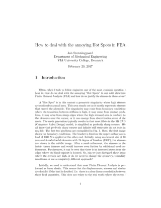
  • 1. How to deal with the annoying Hot Spots in FEA Jon Svenninggaard Department of Mechanical Engineering VIA University College, Denmark February 20, 2017 1 Introduction Often, when I talk to fellow engineers one of the most common question I hear is; How do we deal with the annoying ”Hot Spots” in our solid structure Finite Element Analysis (FEA) and how do we justify the stresses in those areas? A ”Hot Spot” is in this context a geometric singularity where high stresses are confined to a small area. This area stands out as it mostly represents stresses that exceed the allowable. The singularity may come from boundary conditions where the transition between stiffness is high, it may come from contact prob- lems, it may arise from sharp edges where the high stressed area is confined to the elements near the corner, or it can emerge from discretization error of the mesh. The mesh generation typically results in that most fillets in the 3D CAD (Computer Aided Design) model, is simplified as perfectly sharp corners. We all know that perfectly sharp corners and infinite stiff structures do not exist in real life. The first two problems are exemplified in Fig. 1. Here, the first image shows the boundary conditions. The bracket is fixed on the upper surface and a load of 1000 N is applied at the other end. Initially, using an element size of 10 mm and 8-noded solid elements with 24 degree of freedom (DOF), the stresses are shown in the middle image. After a mesh refinement, the stresses in the inside corner increase and would increase even further by additional mesh re- finements. Furthermore, it can be seen that there is an increased stress near the edges where the fixed support is located. So, can we just disregard these areas where the stresses are high or do we need to change the geometry, boundary conditions or use a completely different approach? Initially, we need to understand that most Finite Element Analysis is per- formed as linear elastic. This means that the displacements, stresses and strains are doubled if the load is doubled. I.e. there is a clear linear correlation between those field quantities. This does not relate to the real world where the stress - 1
  • 2. Figure 1: A random bracket is loaded with 1000 N on the right end and fixed on the upper surface. The middle image shows the unaveraged first principal stress with an element size of 10 mm. The third image displays increased stress at the corner with an element size of 5 mm. strain relationship in most ductile metallic materials is only linearly related until a certain point. After this, yielding and plasticity are the governing parameters and the linear force - displacement relationship is no longer valid. Thus, when we see stresses that are far beyond the ultimate limit strength, often this is not the entire truth and a singularity or ”Hot Spot” may be present. Moreover, sharp corners in real life are always rounded. Even if it cannot be seen by the naked eye it will seem rounded if observed through a microscope. This even ap- plies for most sharp cracks. However, even if smaller loads are applied to very sharp corners or cracks, the geometry alters due to crack tip localized plasticity and the stresses distribute as if the corner was rounded. Nonetheless, it is highly important to estimate the strain or stress condition at these locations correctly if fatigue loading is involved. If fatigue loading is involved, the plastic strain- ing due to the presence of sharp corners can easily lead to the formation and propagation of cracks, which ultimately could lead to a complete loss of bearing capacity in the structure. This also applies if static loadings are involved as the stress concentration factor could lead to stresses above the ultimate limit stress of the material and a sudden rupture might occur. 2
  • 3. 2 How to deal with it? The first thing to consider when a ”Hot Spot” is observed is obviously to carry out a mesh convergence study. This would give the engineer information about the stress gradient in the area, and if appropriate elements and element sizes have been used! One method is to utilize one of several adaptive meshing tech- niques; These are the p-refinement technique that changes the polynomial or- der of the element. The r-refinement technique that relocates elements and the mesh. Or the h-refinement technique that refines the mesh in areas of high stress gradients. Even combinations hereof exists as for example the hp-refinement technique. Some of these techniques are usually build into commercial finite element software packages. The h-refinement and p-refinement techniques uti- lizes the posteriori Zienkiewicz - Zhu (ZZ) error estimate [1] that is determined as: ||U||2 = m i=1 { } T i [E] { }idV (1) Here, m is the number of elements in the structure or area of interest, [E] is the constitutive matrix and { } is the strain vector. The global energy error norm in the structure is determined as: ||e||2 = m i=1 ({ ∗ }i − { }i) T [E] ({ ∗ }i − { }i)dV (2) Here, { ∗ } represents the smoothed strain field over the entire structure. Thus, the global energy error norm gives a measure of the variation of energy within the structure. This is then utilized to find the relative error in the structure as: η = ||e||2 ||U||2 + ||e||2 1/2 (3) This relative error η, can take values in the range; 0 > η > 1. Consequently, a good discretization is usually obtained with η ≤ 0.05. For the case of the h-refinement technique this is illustrated in Fig. 2. Here, the plate is loaded by an evenly distributed load on the top edge and fixed along the edge A-B. Using adaptive meshing with the h-refinement technique, the mesh is refined around the corners. With increasing mesh density, the stress at these points will tend towards infinity. Already after the first mesh revision, the engineer would realize that he or she instead, should consider changing the boundary conditions, or simply disregard these areas from the stress analysis. The example illustrated in Fig. 2, is further visualized in Fig. 3. Using the commercial software Ansys Workbench, the difference between the left boundary being completely fixed and it being subjected to a different boundary condition is easily seen. The analysis shown in Fig. 3 a) to c) never converges! The mesh 3
  • 4. Initial mesh with linear strain triangles LST A B q First revision of the mesh using adaptive meshing with the h - method Second revision of the mesh using adaptive meshing with the h - method A B q A B q y x Figure 2: Results from adaptive meshing of a 2D plate subjected to plane stress. The plate is completely fixed on the edge A-B. Each mesh revision aimed at η = 0.05. (Freely inspired from [1]) density is increased in the corners by each iteration and the stress increases. In Fig. 3 d) and e). The analysis converges with within a few iteration. This is illustrated in f). The relative error η in the model cannot directly be plotted, but it can be scripted quite easily in most FE packages. a) b) c) d) e) f) Figure 3: 2D Analysis of plate loaded with a distributed load of 5 MPa on the top edge. Sub figures a) to c) shows the effect, when the entire left boundary is fixed. Sub figures d) and e) shows the effect of the upper and lower left boundary edge being locked in the horizontal direction. The middle left segment is locked in both horizontal and vertical direction. Sub figure f) shows the convergence curve for d) and e). If we turn our attention towards other methods and approaches, a lot of work has been committed to finding methods to deal with weld details and relating them to a certain Fatigue class (FAT) using the FEM. Most used is probably the ”Nominal stress method” which relates a number of structural details to certain 4
  • 5. fatigue classes or SN - curves. The method has among others been adopted by Eurocode 3, part 1-9, [2] and a series of other 3rd party organizations. This method however, is not directly usable for the above discussed singularities as no listed structural details exists to quantify the various singularities that may emerge in the FEA. A more specialized method that has been standardized by the International Institute of Welding [3] and DNV [4] is the ”Structural Hot Spot method”. This method can be used either with physically mounted strain gauges or the Finite element method. The method is based on that strains or stresses are evaluated at certain distances from the weld toe and extrapolated here to. Then, the stress or strain level of the detail is compared to a certain FAT class. This method can prove quite handy for shell models. For shell models, the stress at sharp corners or transitions between profiles or plates, can be evaluated by extrapo- lating stresses into the corner. Thereby the ”Hot Spot” can be quantified and the stresses can be shown to have an absolute value. Nonetheless, the calculated stress should be considered carefully as other factors might influence. The newest and in my opinion, most promising method with the finite el- ement method, is the ”Effective Notch method” [3]. Here, the corner or weld detail in the 3D CAD model is modeled using a fillet of 1 mm and in the finite element software a max element size of 0.25 mm in this area is applied. Then the maximum principal stress is compared to a FAT 225 curve [5] [6]. Thus, for static applications the computed max stress is compared to the ultimate limit strength of the material. The drawback is that it may be computationally too expensive to use this element size in the entire model. Therefore, it should be considered to use a sub-model of the area of interest. As mentioned earlier, ”Hot Spots” are also common in contact problems. One example is illustrated in Fig. 4. Here, the bolted connection, comprised of frictionless contacts between multiple parts, shows very high stresses in a localized area. Thus, it can be considered a ”Hot Spot”. The high stresses typically originate from non-conforming meshes between the parts, or from a single node connected through contact elements with multiple nodes on the counterpart. A method to justify the stresses in this area could be to use a finer mesh on the parts in contact. This however, might be impossible due to computational expense. Moreover, the area could be used in a sub-model, where the displacements are transferred from the global model. In this sub-model, the mesh can easily be refined and or an elastic - plastic material model can be used. Sometimes, this is not possible. In this case it might be reasonable to extract the contact forces and analyze the connection with traditional analytical methods. These methods could follow standards as for example Eurocode 3, part 1-8 [7] or VDI 2230 [8] or other. 5
  • 6. a) b) Figure 4: Sub-figure a) shows part of the global model of a wind turbine tower and transport equipment. Sub-figure b) shows a part of the transport equipment including the area of high stresses where the bolt was in contact with the tool. 3 Conclusion and discussion This small guide introduces a few methods to handle singularities often referred to as ”Hot Spots” in finite element analysis. The first step should always be to conduct a mesh convergence study in order to make sure that the correct ele- ment sizes and types have been chosen. Automatic adaptive meshing techniques can be used. However, these methods should be handled with care. Moreover, several techniques are described that have been developed for fatigue evaluation of welds. Some of these methods can be utilized to estimate the stress state near corners or areas where the stress gradient is high. Often, contact prob- lems exhibit areas where localized stresses are very high. Here, a sub-model or local mesh refinement might alleviate the problem. Otherwise, the contact forces should be extracted and the contact should be analyzed using analytical methods. 6
  • 7. References [1] Cook, R. D., Malkius, D. S., Plesha, M. E., Witt, R. J., Concepts and applications of finite element analysis, John Wiley and Sons, 4th edition, 2002 [2] Eurocode 3, Part 1-9, DS/EN 1993-1-9+AC, 2nd edition, 2007. [3] Hobbacher, A., Recommendations for fatigue design of welded joints and components, IIW document IIW-1823-07 ex XIII-2151r4-07/XV-1254r4-07., 2008. [4] Det Norske Veritas AS Fatigue Design of Offshore Steel Structures DNV- RP-C203, Recommended practice, October 2011. [5] Pedersen, M. M., Mouritsen, O. ., Hansen, M. R., Andersen, J. G. Experience with the Notch Stress Approach for Fatigue Assessment of Welded Joints, Proceedings of the Swedish Conference on Light Weight Optimized Welded Structures, 2010. [6] Pedersen, M. M. Multiaxial fatigue assessment of welded joints using the notch stress approach, International Journal of Fatigue 83 October 2015. [7] Eurocode 3, Part 1-8, DS/EN 1993-1-8+AC, 2nd edition, 2007. [8] VDI Richtlinien, VDI-2230, Systematic calculation of high duty bolted joints - Joints with one cylindrical bolt, February 2003. 7