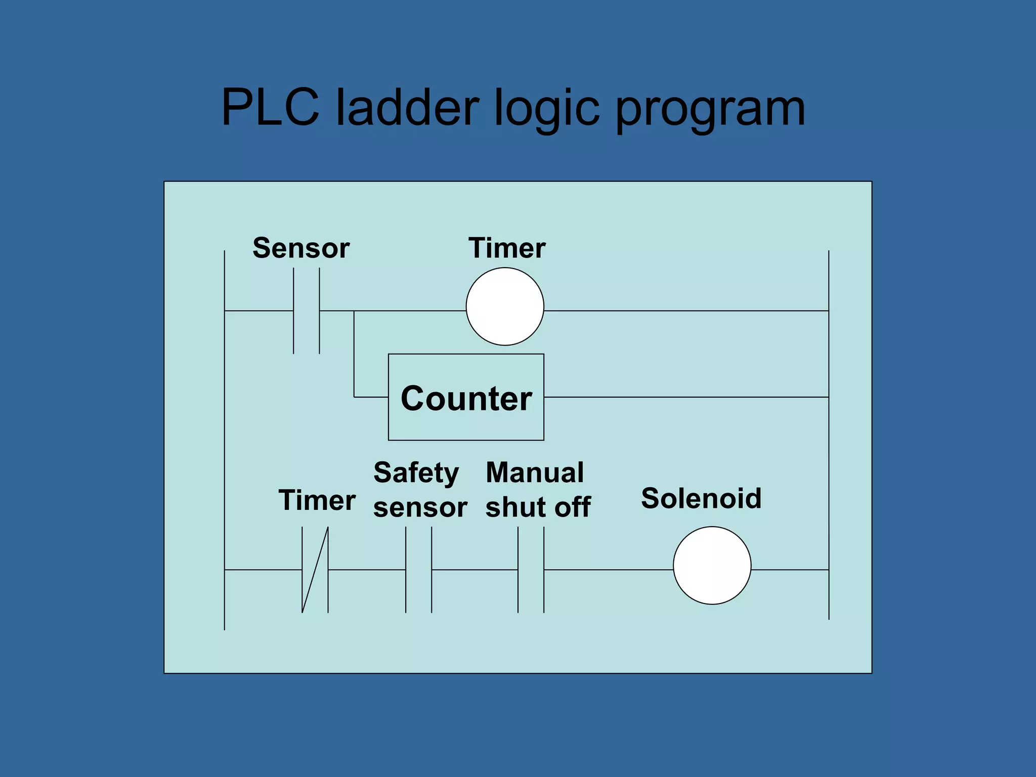
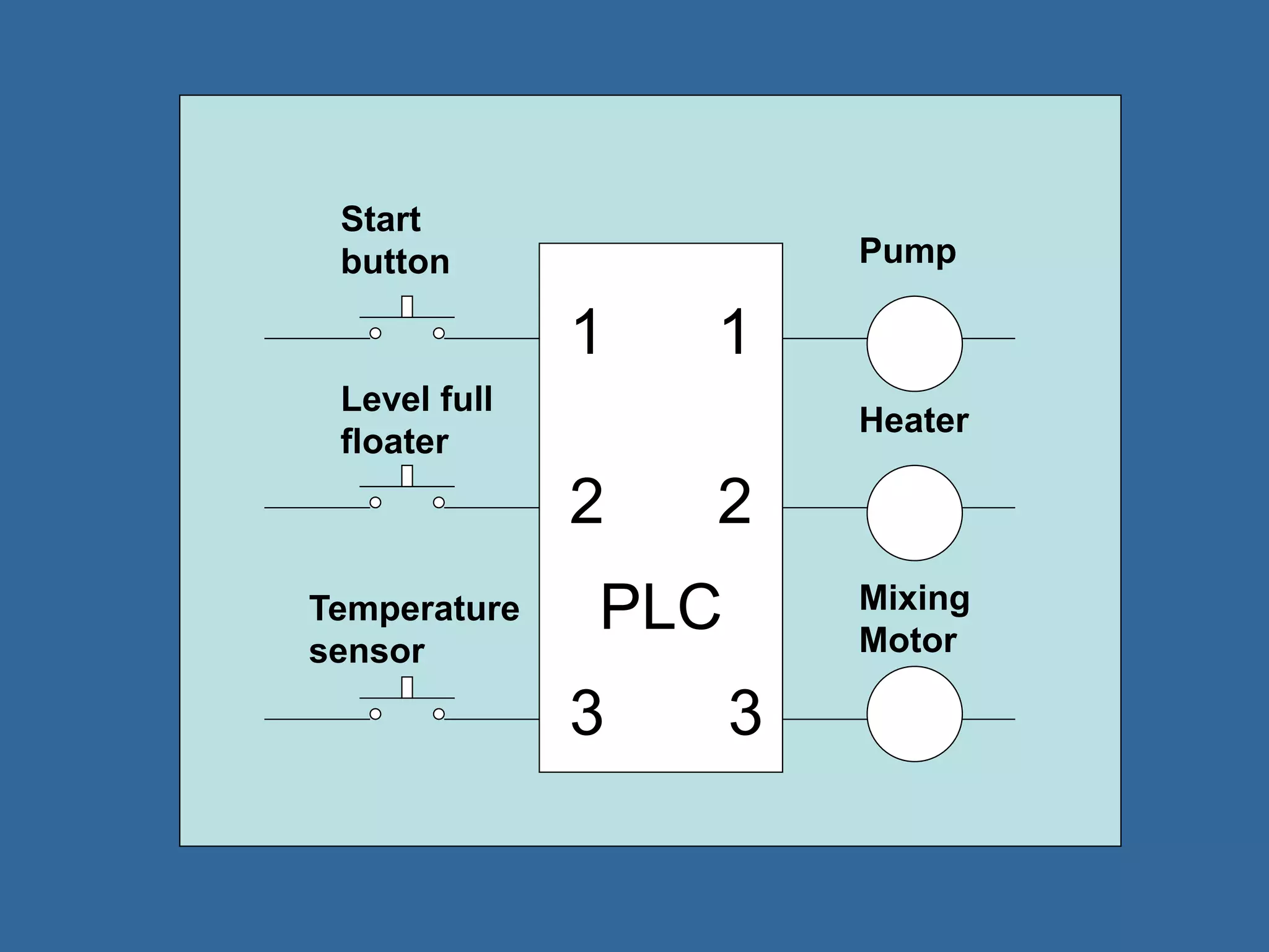
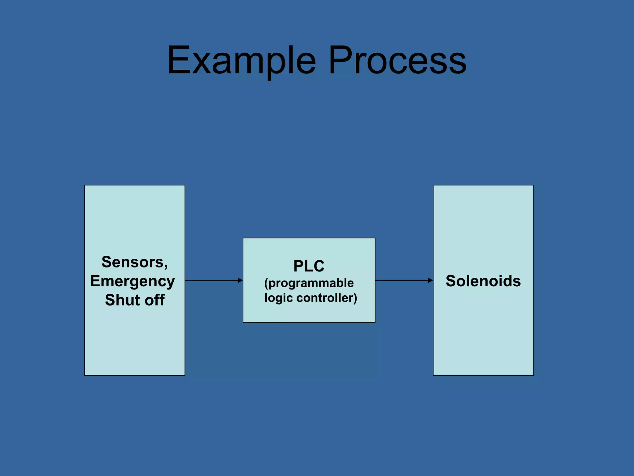
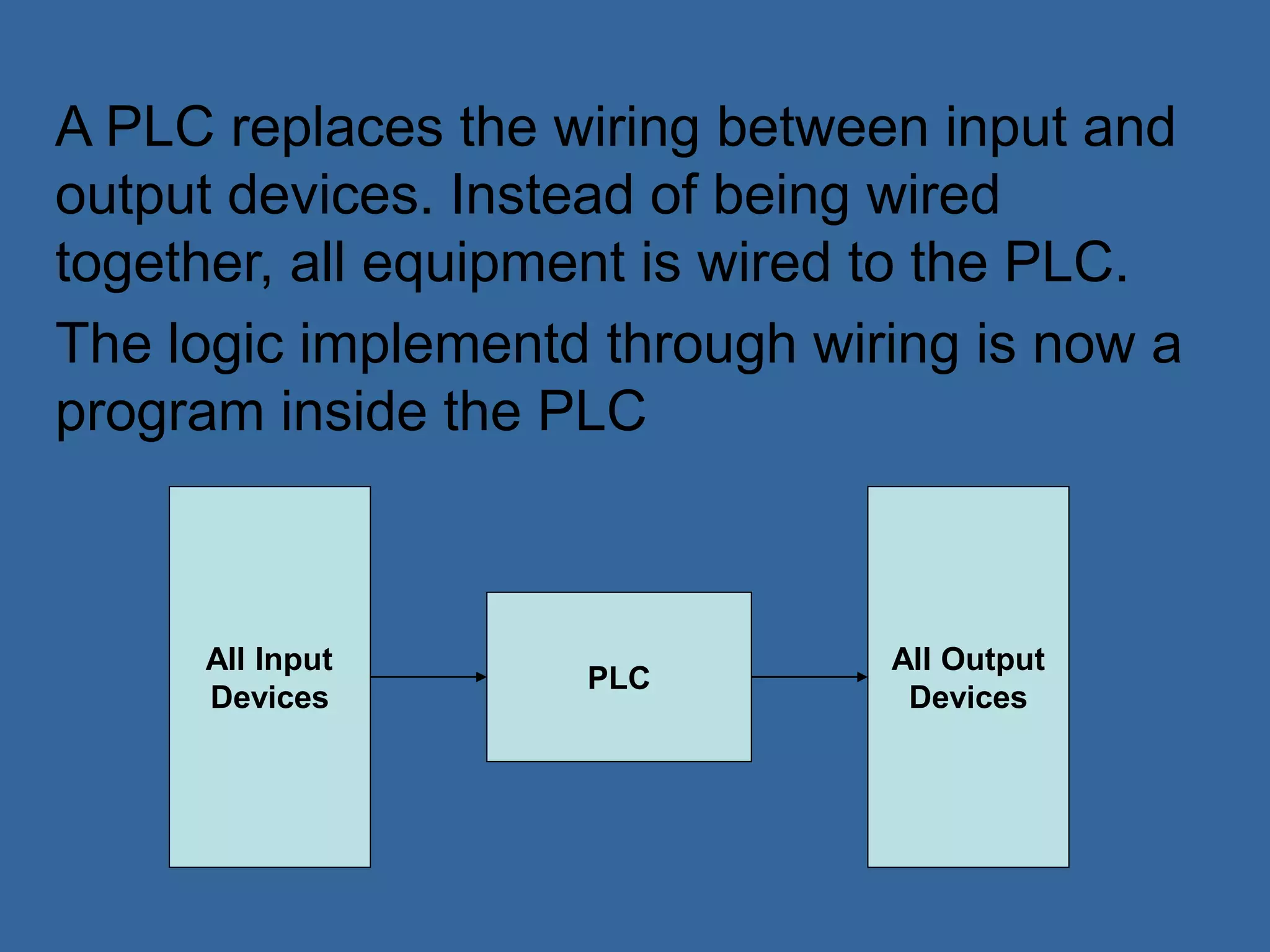
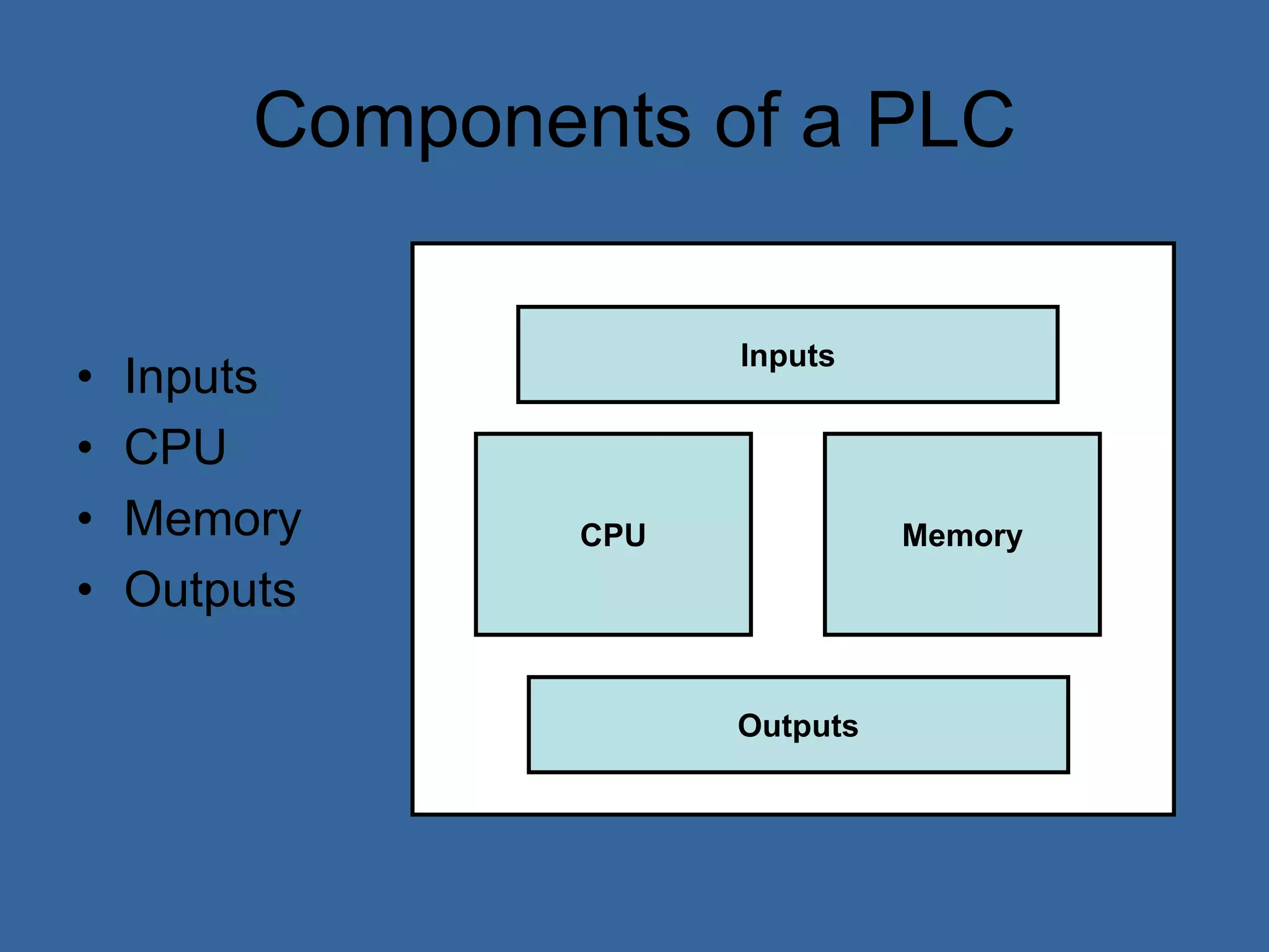
Programmable logic controllers (PLCs) are industrial computers used to monitor inputs and control outputs on automated machinery. PLCs read sensors as inputs, run user-written control programs, and activate outputs such as motors or valves. Ladder logic is the most common programming language for PLCs, resembling relay-run logic diagrams. PLCs scan inputs, execute programs, and update outputs continuously to automate industrial processes.
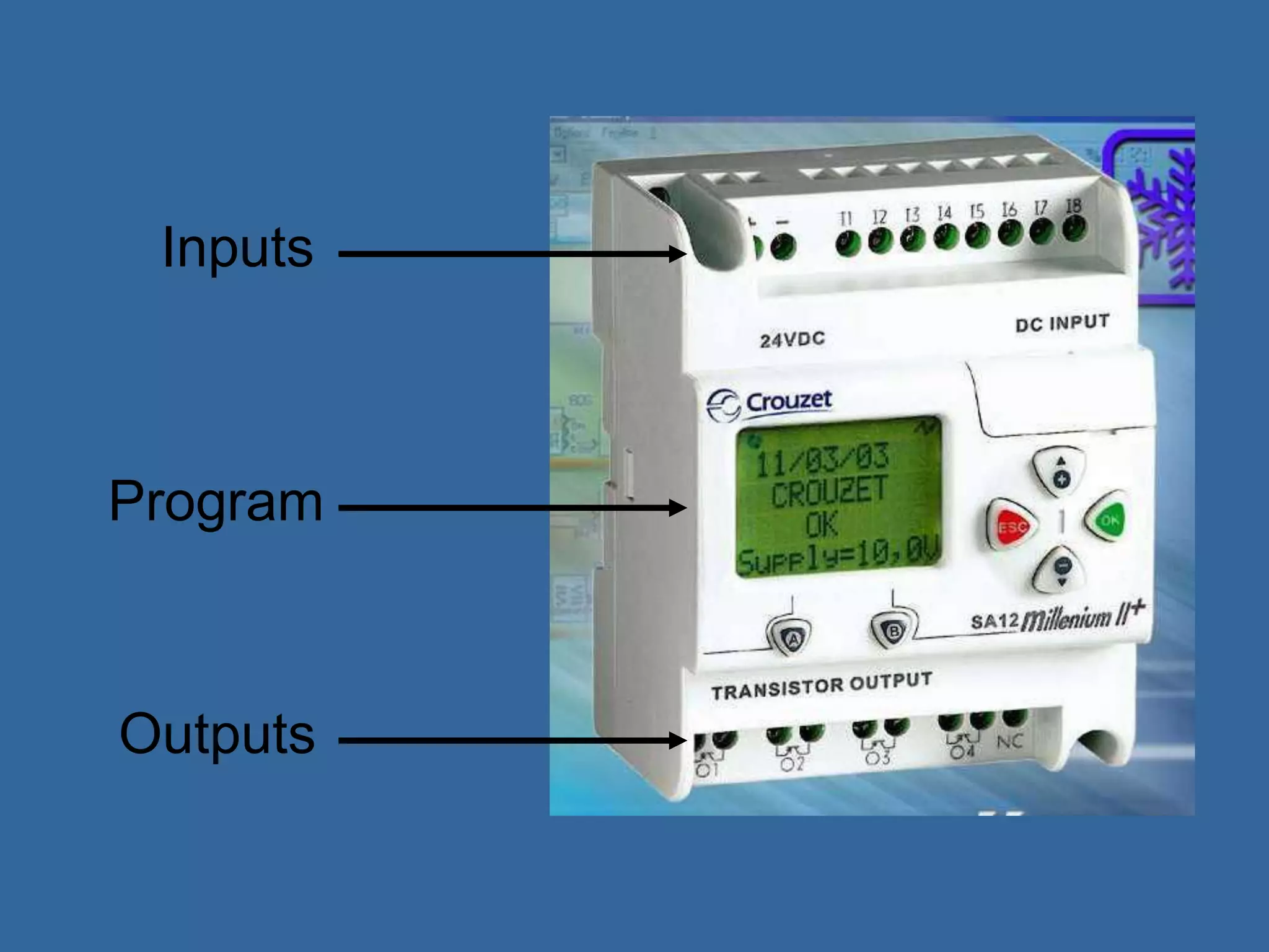
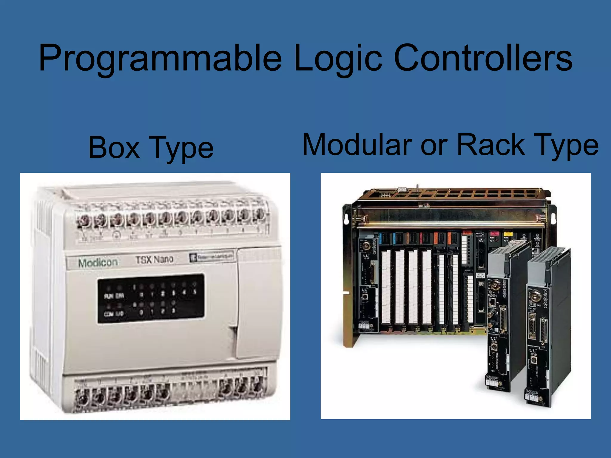
![Programmable Logic Controllers
• PLCs (Programmable Logic Controllers) is
a miniature industrial computer performs
control functions [4]
• The first PLCs can be traced back to 1968
and became popular in the 1980’s [4]
• PLCs are rugged and designed to
withstand the industrial environment.](https://image.slidesharecdn.com/anintroductiontoplcs-200115170620/75/An-introduction-to-pl-cs-16-2048.jpg)
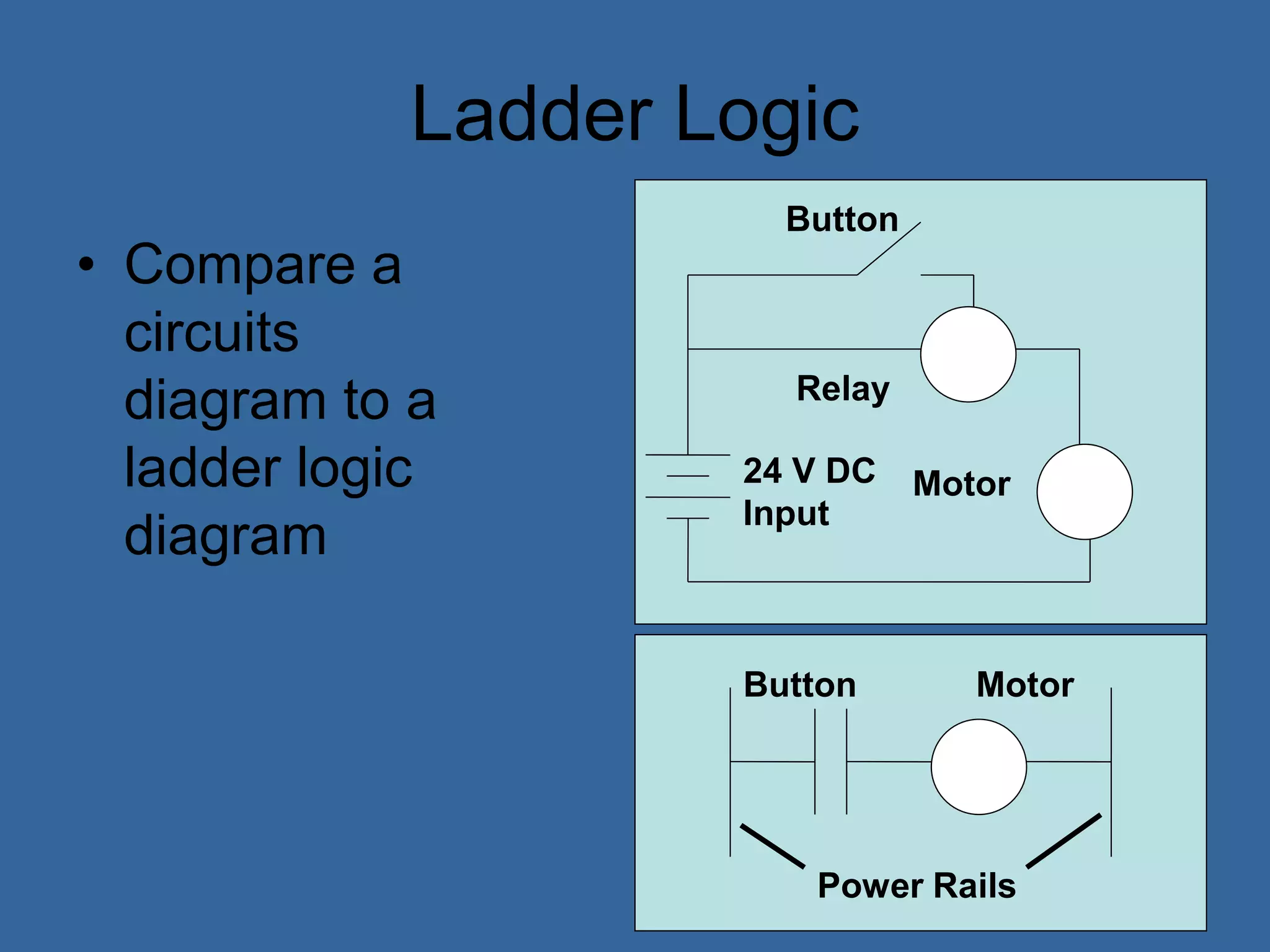
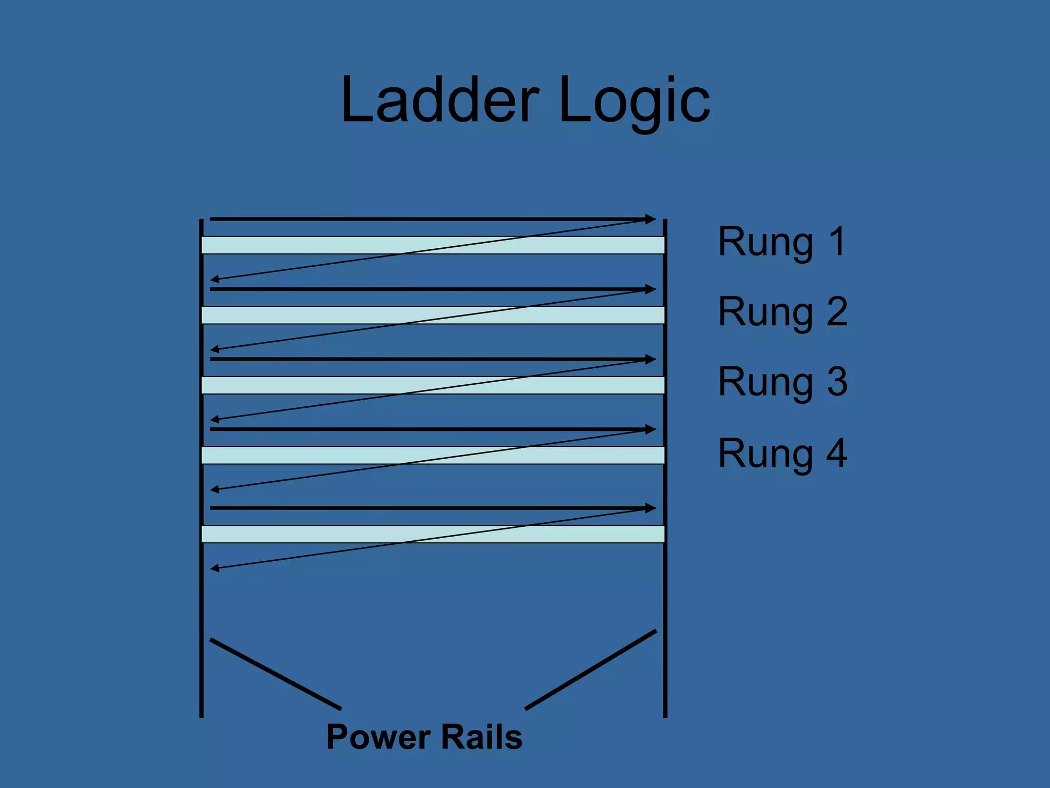
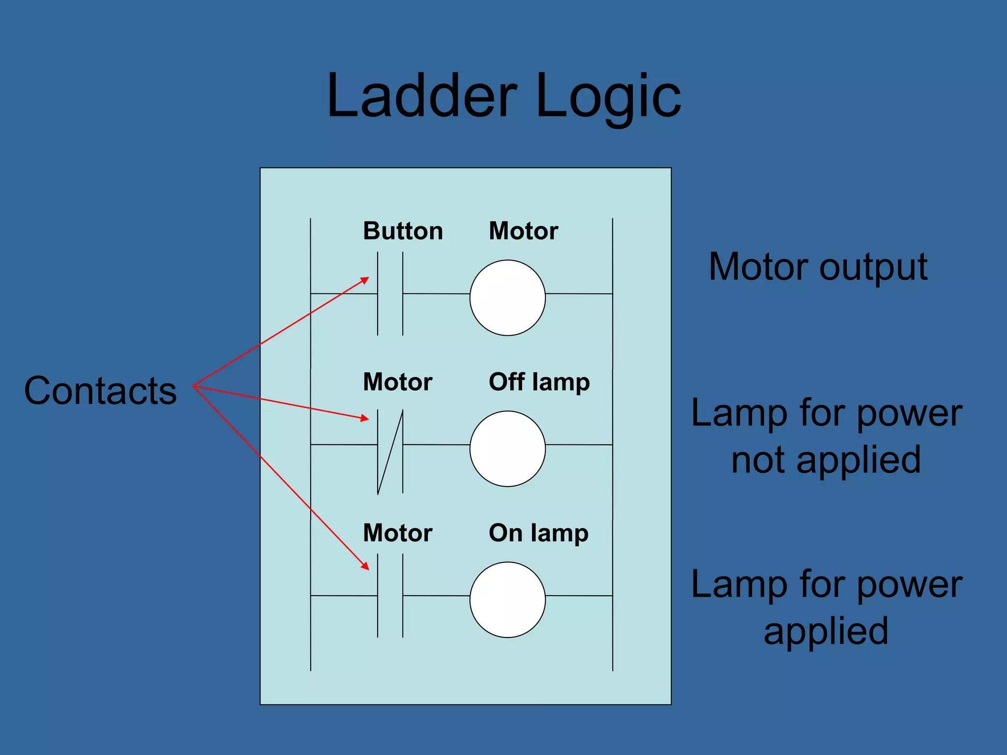
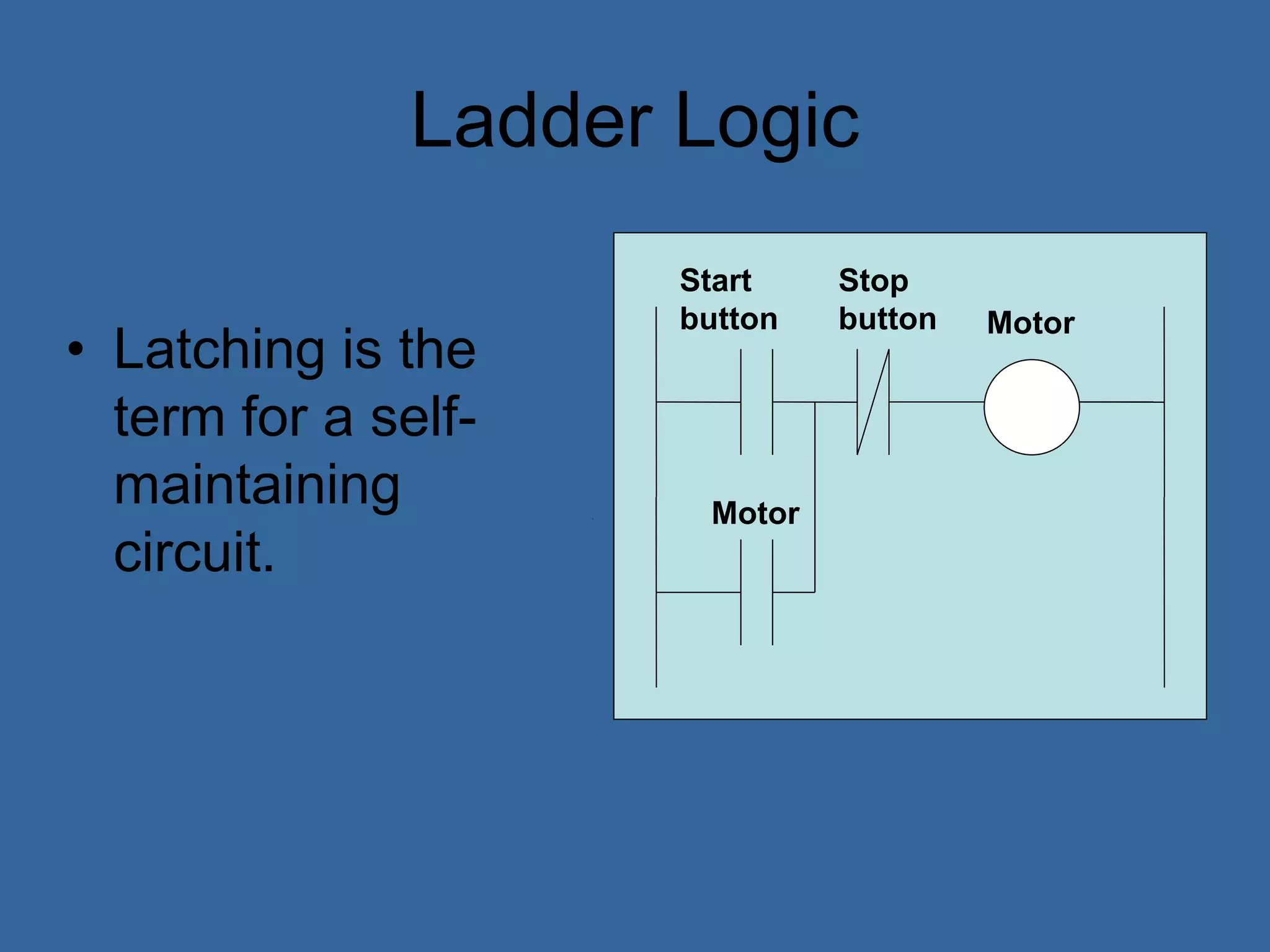
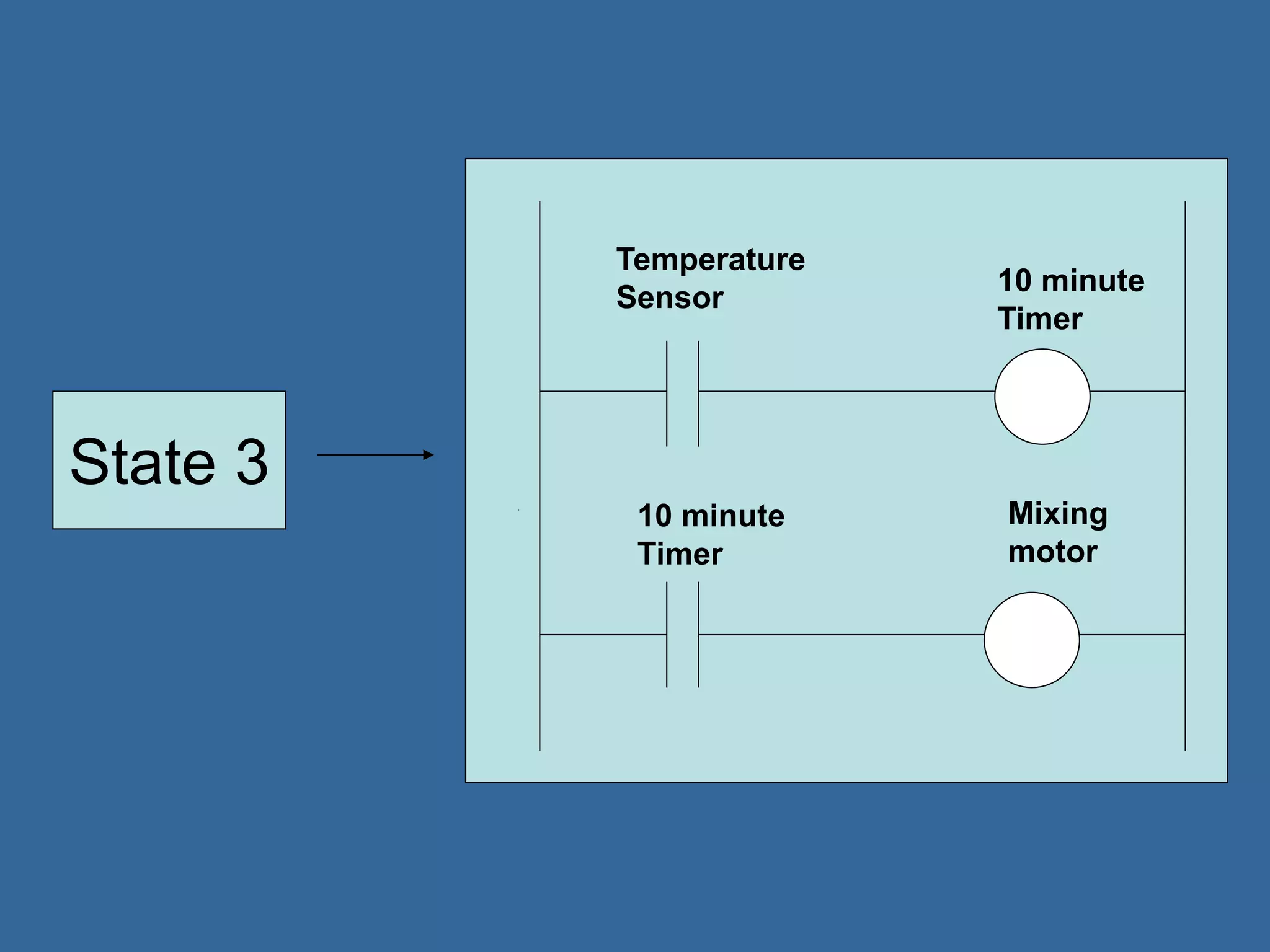
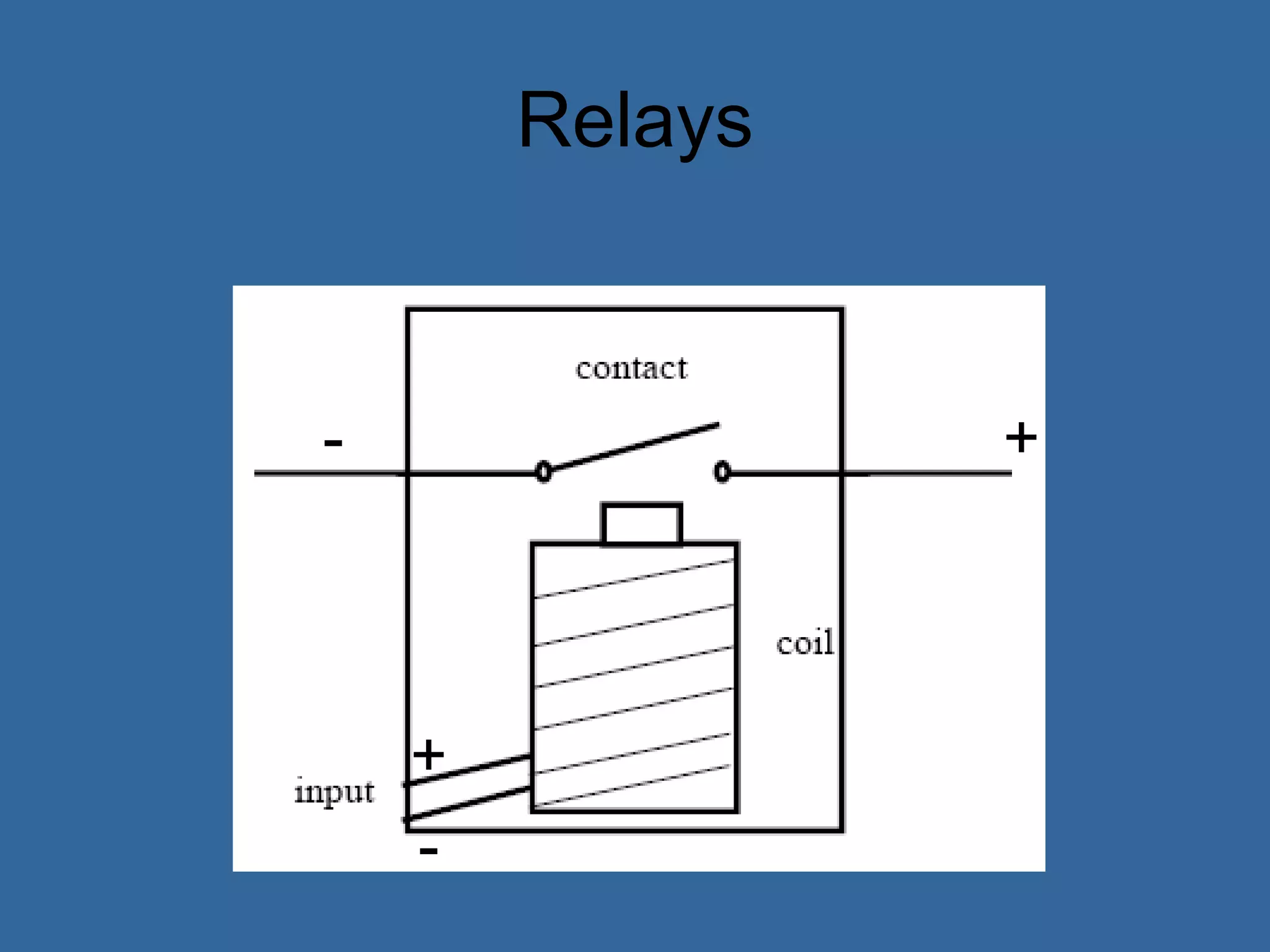
![PLC Programming
• Ladder logic is the main programming
method used for PLCs [39]
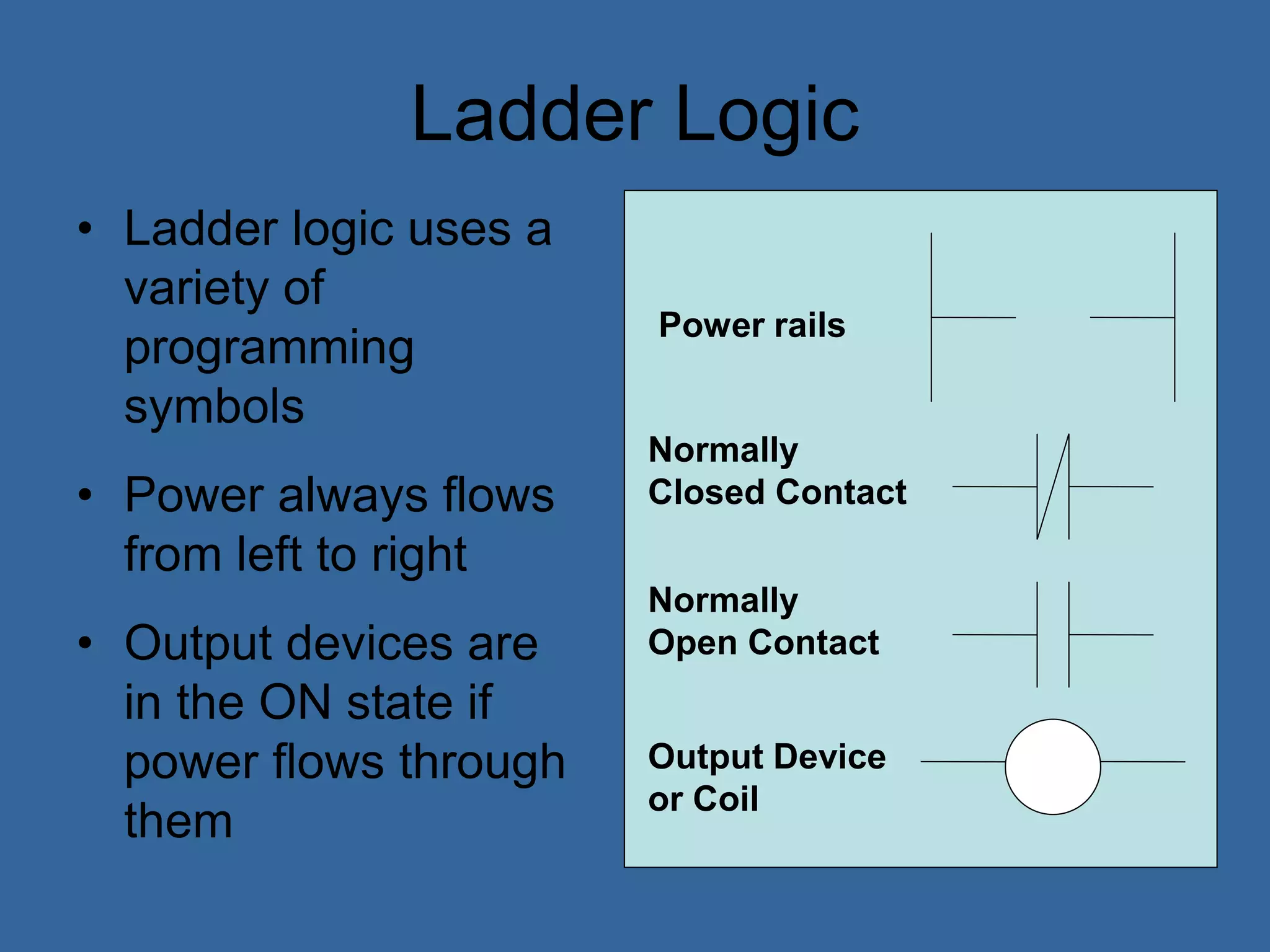
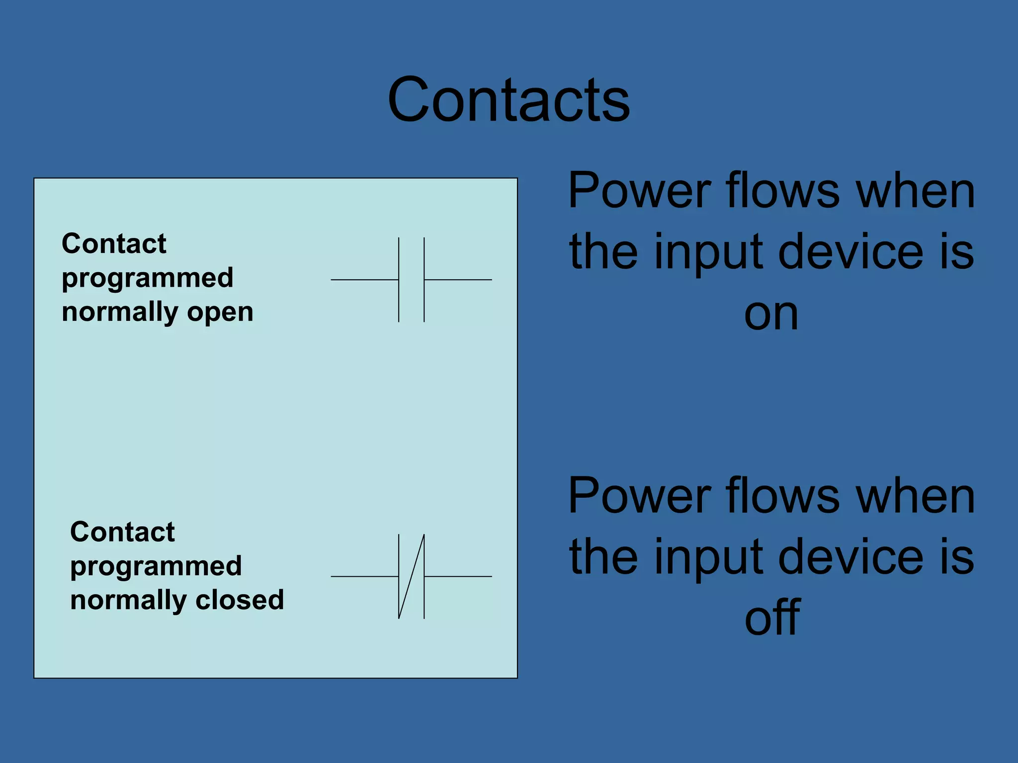
• It is a visual and symbolic programming
language that resembles relays logic
diagrams
• Ladder logic has been developed to mimic
relay logic to reduce amount of retraining
needed for engineers and trades people
[39]](https://image.slidesharecdn.com/anintroductiontoplcs-200115170620/75/An-introduction-to-pl-cs-20-2048.jpg)