Download as PDF, PPTX

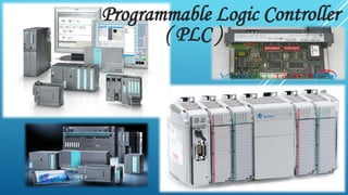
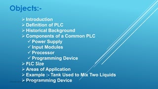
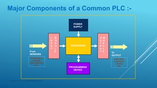
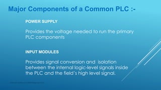
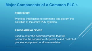
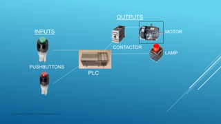
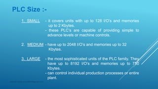
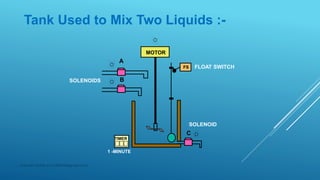
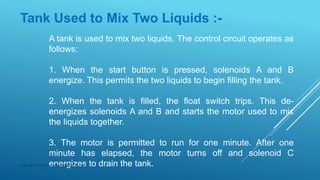
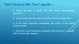
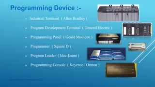
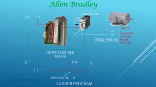


This presentation provides an introduction to programmable logic controllers (PLCs). It defines a PLC as a solid state electronic device that can be programmed to control machines and processes. The presentation outlines the typical components of a PLC including the power supply, input and output modules, processor, and programming device. It also discusses PLC sizes, common applications in manufacturing and industry, and provides an example of how a PLC could control a tank used to mix two liquids.