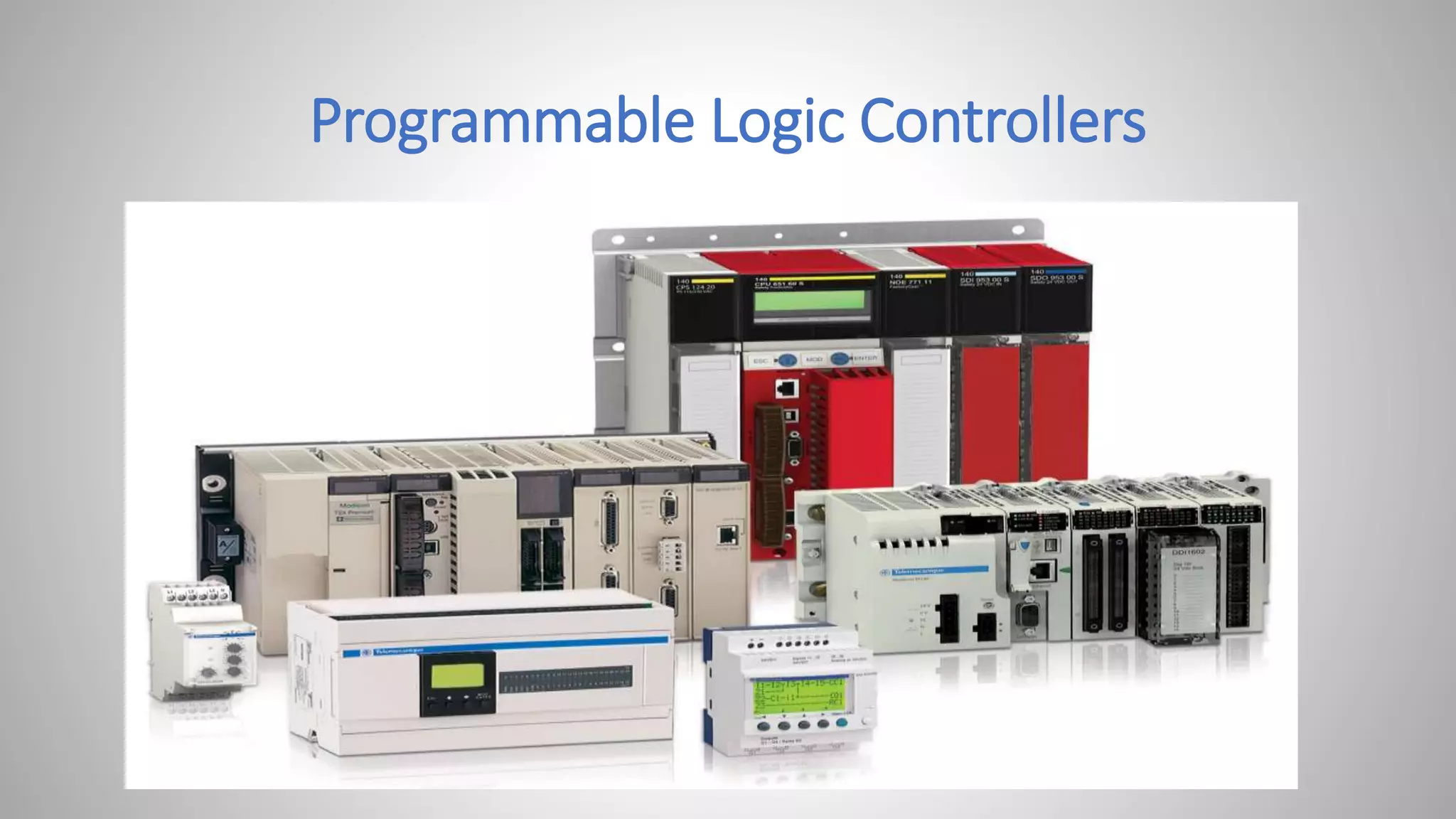
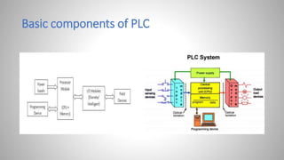
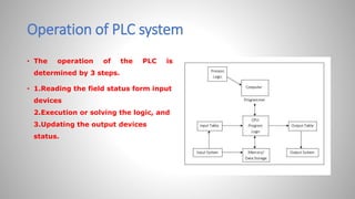
2. Programmable Logic Controller- Evolution
• It is a special purpose computer
• a modern controller replaced the olden relay logic ( ON/OFF)
• More operating time / fail frequently
• Power consumption is more
• Less flexibility and difficult in trouble shooting
3. What is PLC?
• Programmable logic controller / programmable controller
• Used for industrial Automation Process
• A specific memory to store the logics/ON-OFF, timing , counting,
arithmetic, control of various machines
• Designed for multiple input and out put arrangements
5. • CPU and Memory Module:-
This is the device where PLC program is stored and processed. The size and type of
CPU determines the programming functions available, size of the application logic
available, amount of memory supported, and processing speed.
• Power Supply:-
The power supply provides power for the PLC system. It provides internal DC
current to operate the processor logic circuitry and input/output assemblies. This
can be built into the PLC or an external unit. Common voltage levels required by
the PLC are 24Vdc, 120Vac, 220Vac. , is used to determine temperature.
6. • Input and Output Module:-
Inputs carry signals from the field (process) to the controller. Various types of inputs can be
switches, pressure sensors, transmitters etc. The field devices to whom PLC sends the results
of logical operations are the output devices. These are the actuators that adjusts or control
the process, motors, lights, relays, pumps, etc. Many types of inputs and outputs can be
connected to a PLC and they can be categorized mainly as analog and digital. Digital inputs
and outputs operate on discrete or binary change i.e. on/off, open/close. Analog inputs and
outputs change continuously with reference to time.
• Programming Device:-
The PLC is programmed using a special software using computer or Hand Held Terminal(HHT)
that can load and change the logic inside.
7. Operation of PLC system
• The operation of the PLC is
determined by 3 steps.
• 1.Reading the field status form input
devices
2.Execution or solving the logic, and
3.Updating the output devices
status.
8. PLC Programming
1.Textual Language
1. Instruction list
2. Structured text
2.Graphical Form
1. Ladder Diagrams (LD) (i.e. Ladder Logic)
2. Function Block Diagram (FBD)
3. Sequential Function Chart (SFC)
10. Types of PLC
Compact PLC
It will be in single case, fixed I/O modules, Expansion is not possible
Modular PLC
It has multiple expansion through modules. I/O components can be
changed / extended. All are independent to the other.
11. Some of the manufacturers of PLCs include:
• Allen Bradley
• ABB
• Siemens
• Mitsubishi PLC
• Hitachi PLC
• Delta PLC
• General Electric (GE) PLC
• Honeywell PLC
12. Applications of PLC
1.Process Automation Plants (e.g. mining, oil &gas)
2.Glass Industry
3.Paper Industry
4.Cement Manufacturing
5.In boilers – Thermal Power Plants
Few onboard ships applications of PLC
• Boiler control
• Generator control and its load management
• Engine room alarms etc.,
13.
14.
15. PLC Programming ( LD)- logic gates
• Logic gates are the basic building blocks of any digital system.
• It is an electronic circuit having one or more than one input and only
one output.
• The relationship between the input and the output is based on a
certain logic.
• Based on this, logic gates are named as AND gate, OR gate, NOT gate
etc.
19. A signal lamp is required to be switched on if a pump is running and the pressure is
satisfactory, or if the lamp test switch is closed. In this application, if there should be
an output from the lamp inputs from both pump and pressure sensors are required.
Hence, AND logic gates are used.