Downloaded 587 times
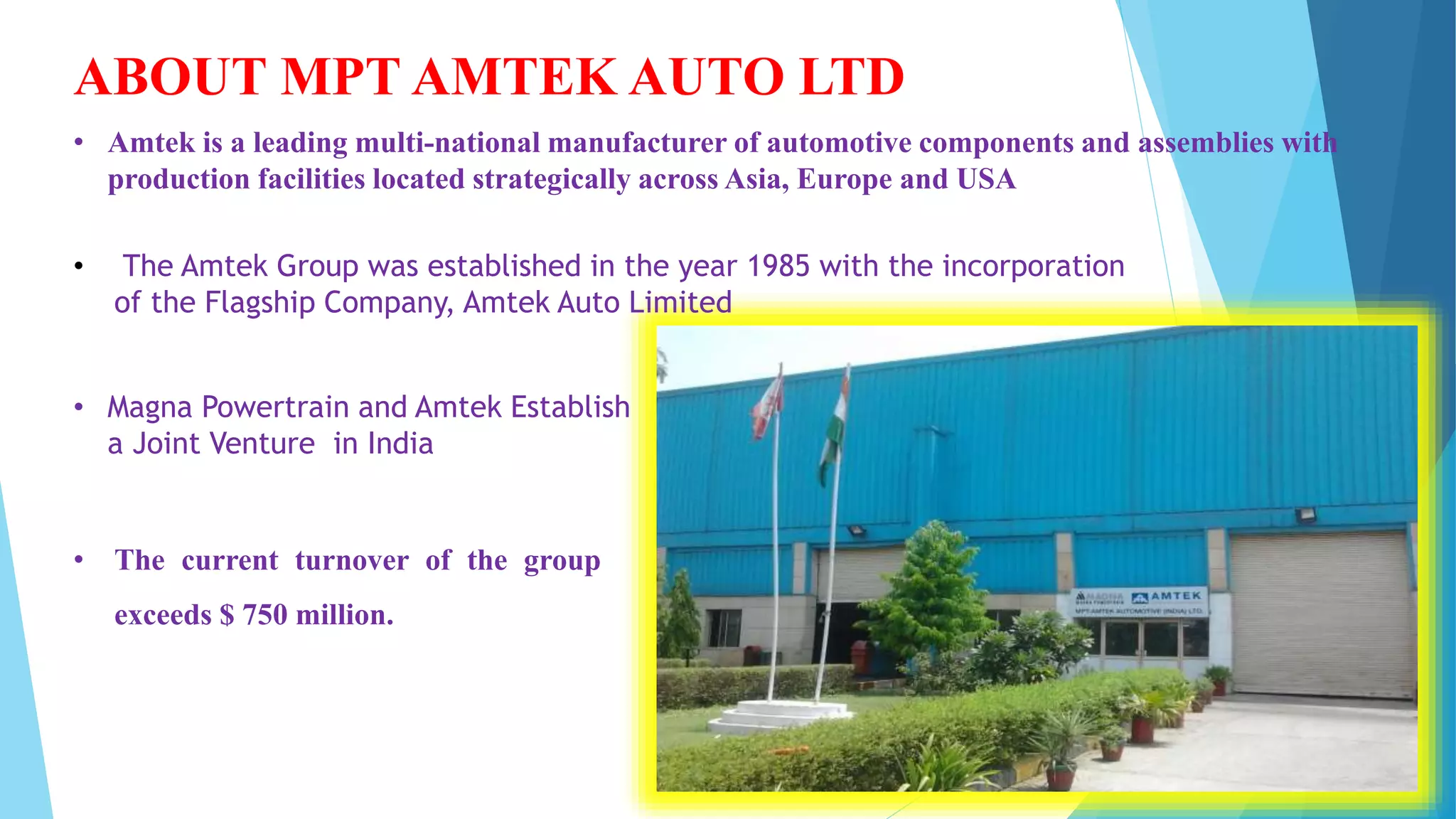
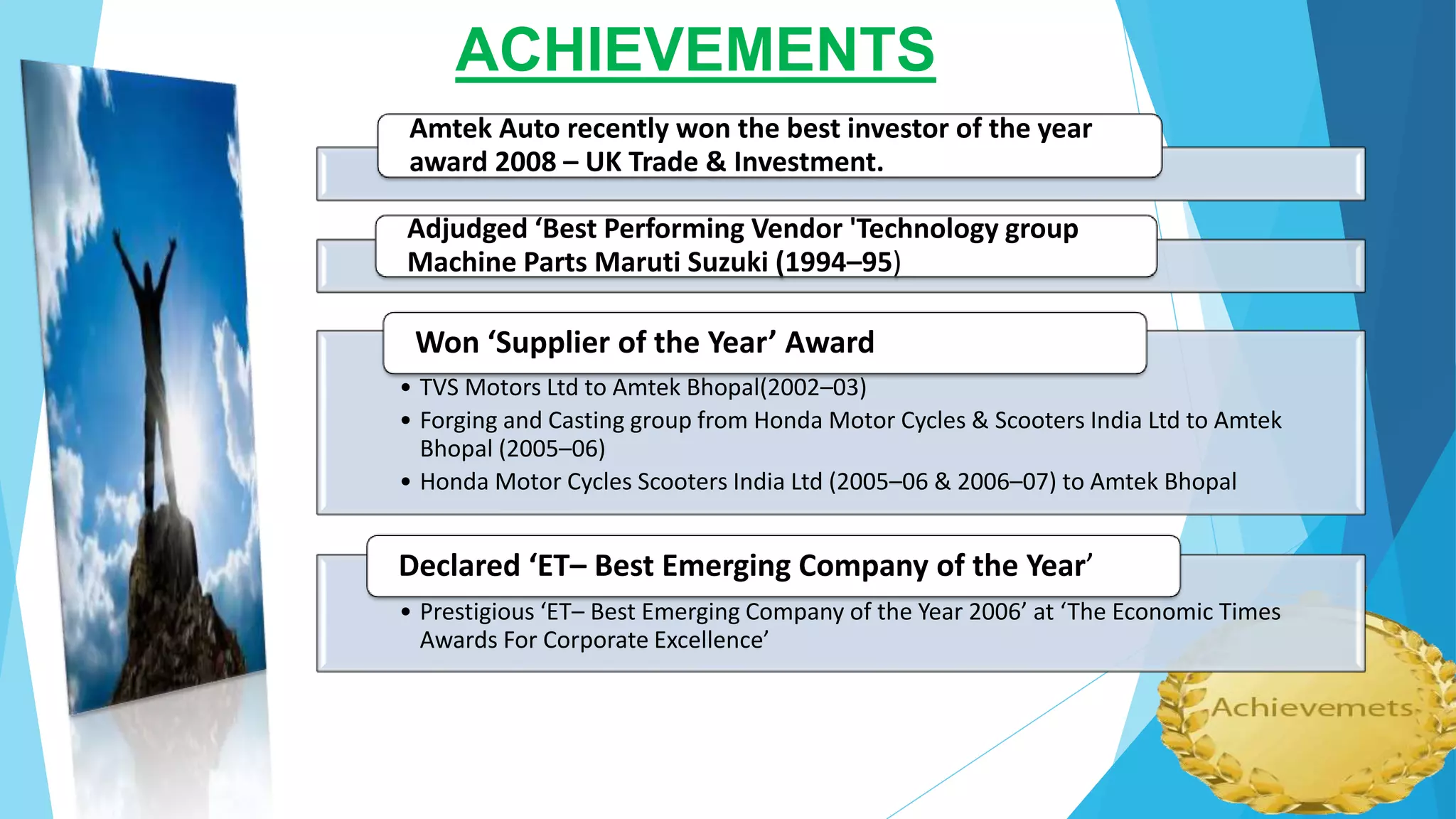
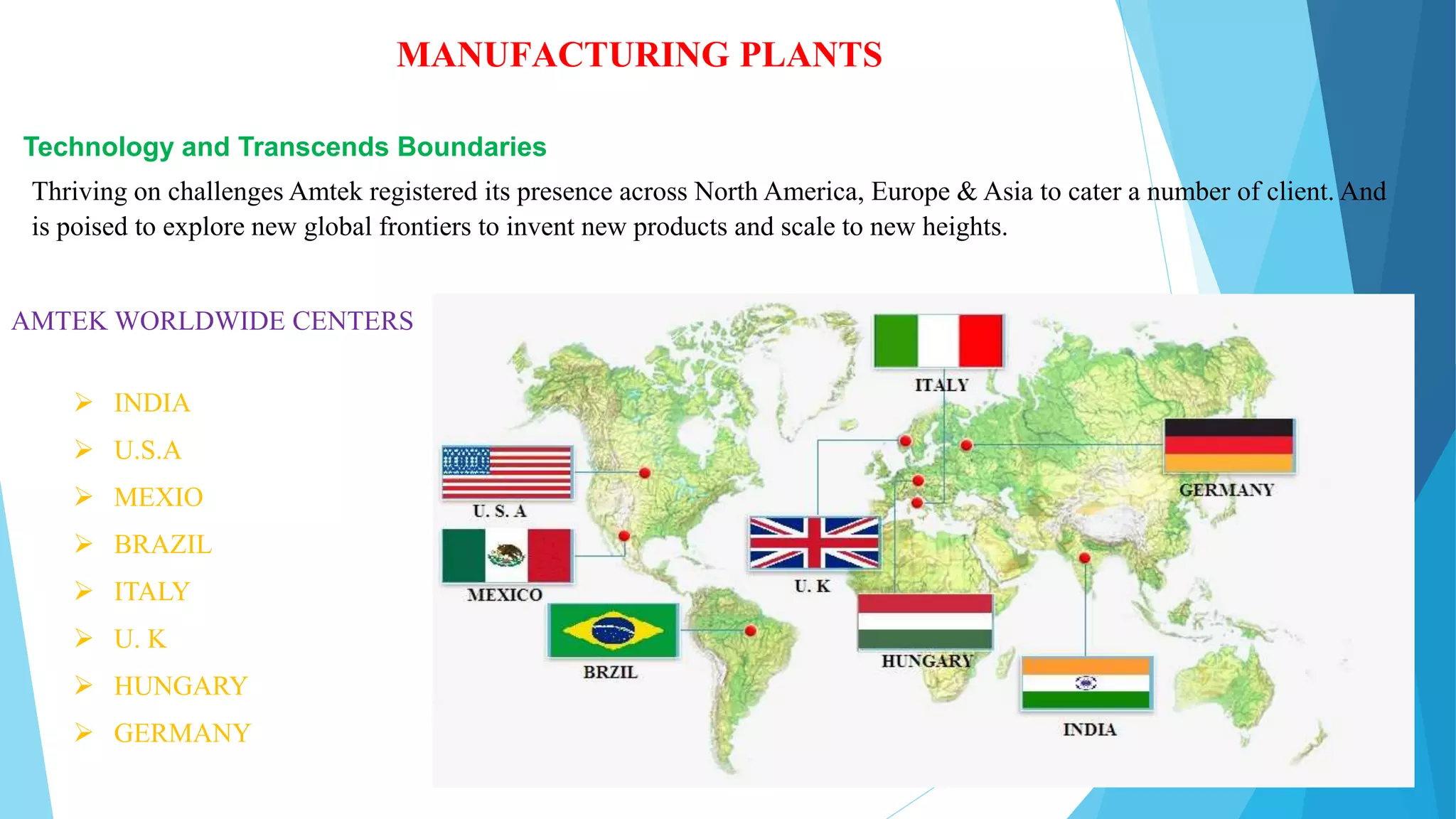
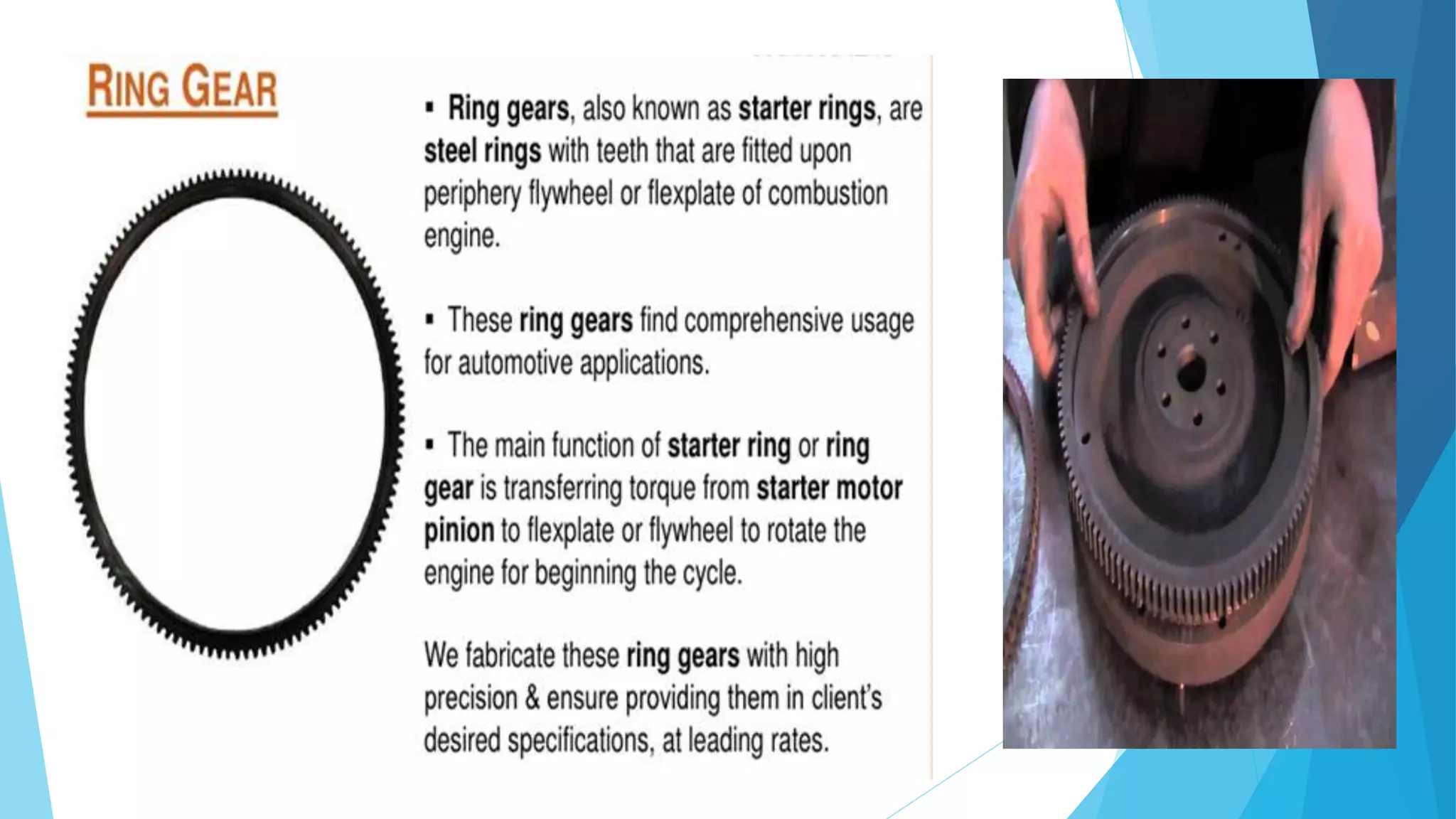
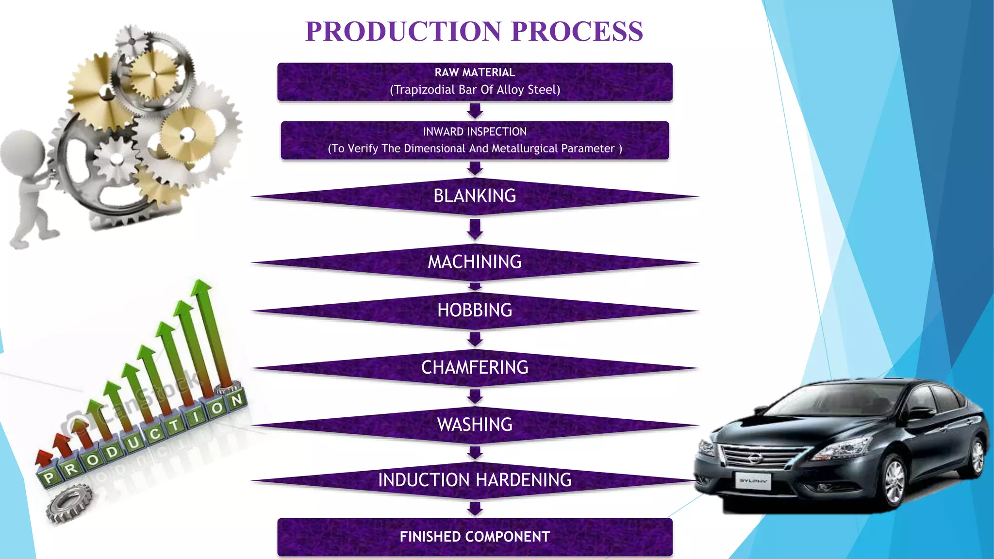
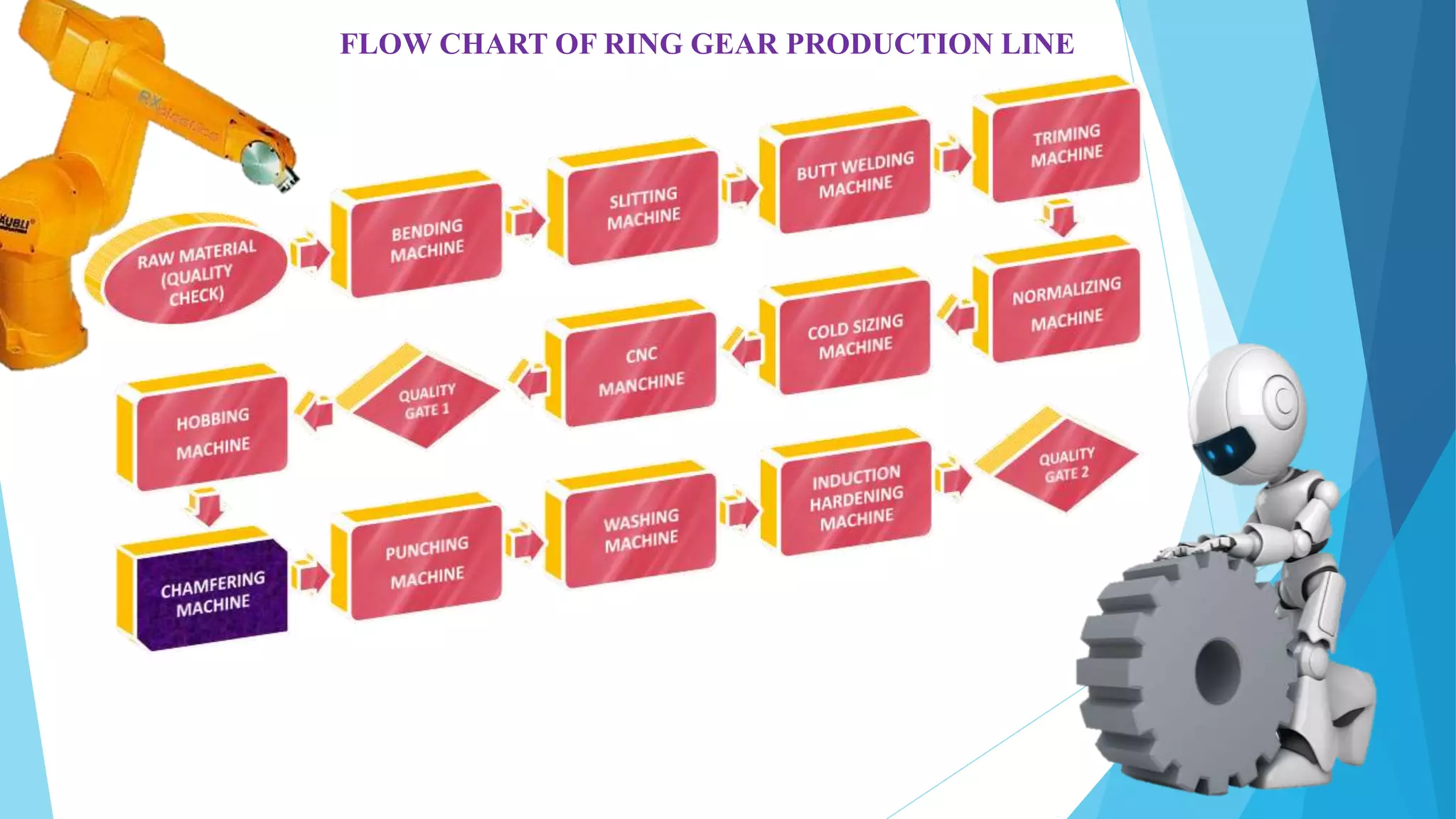
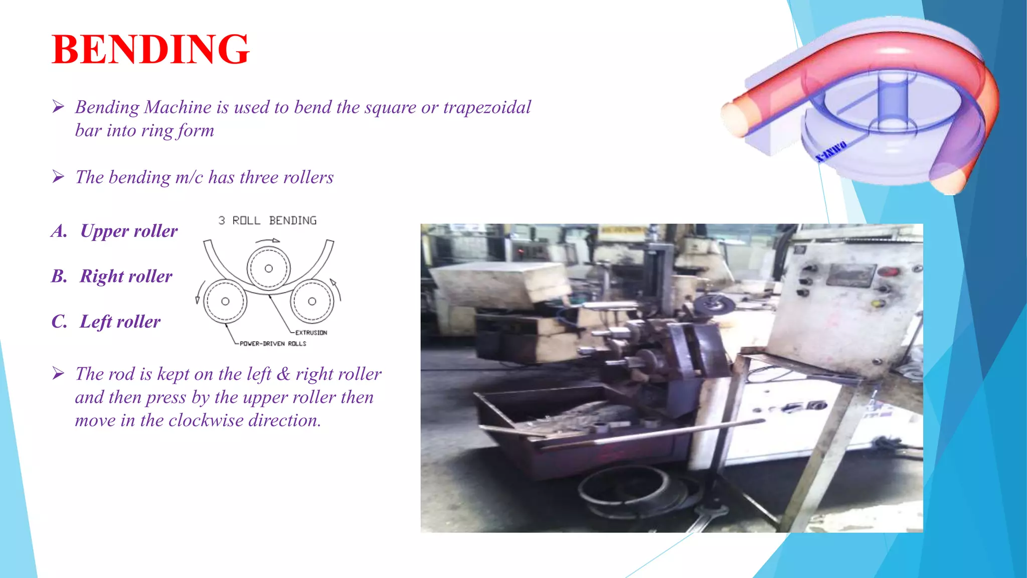
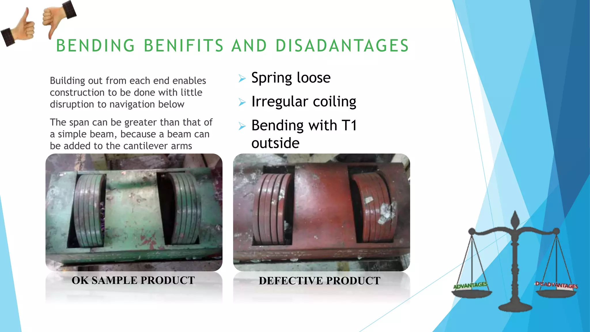
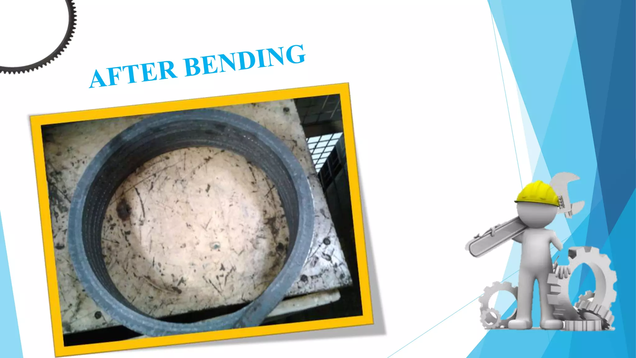
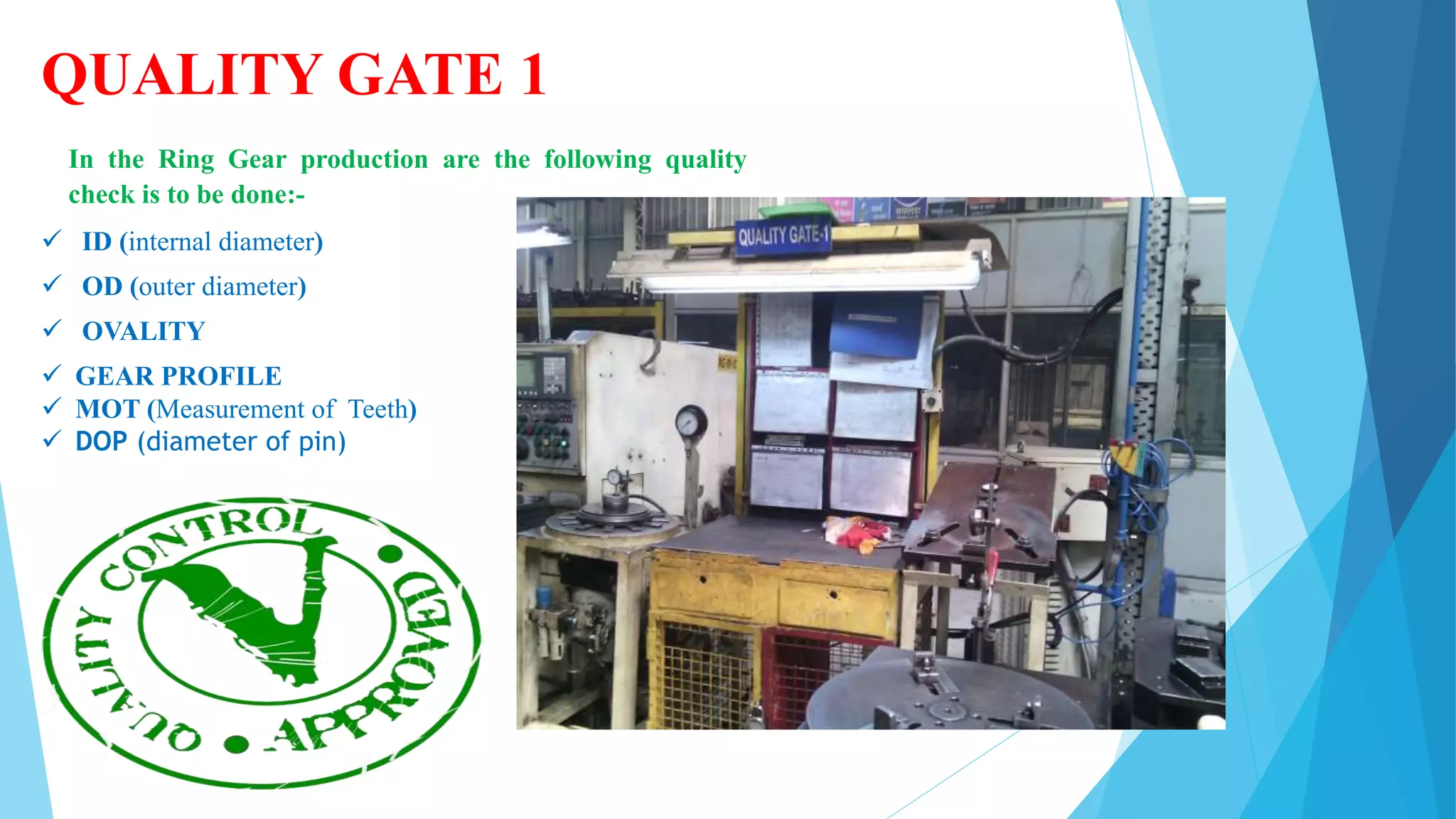
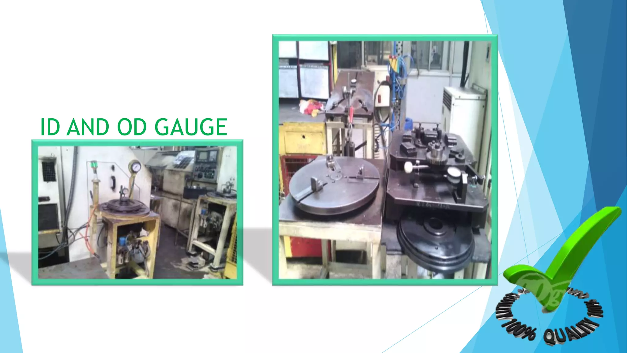
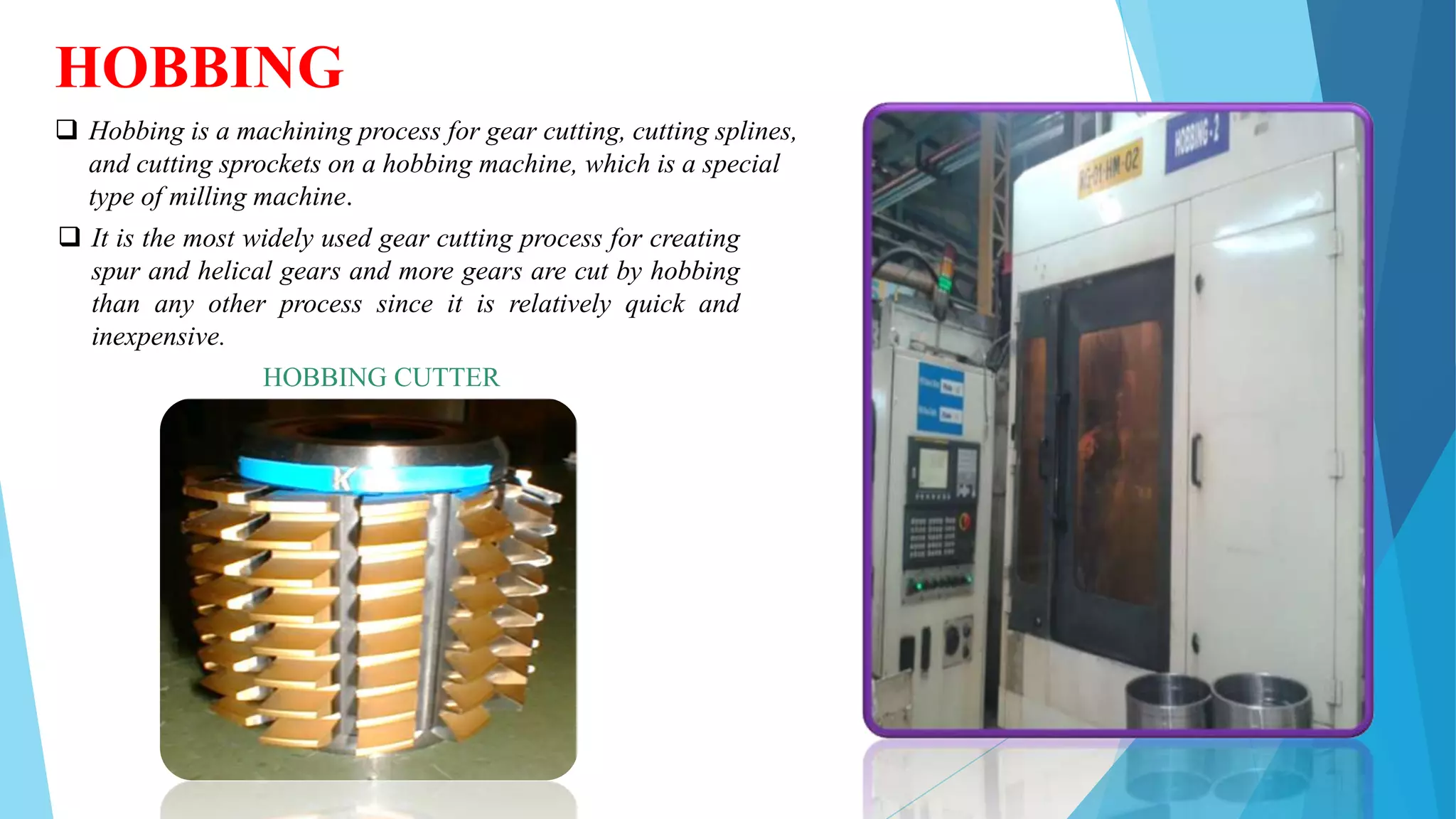
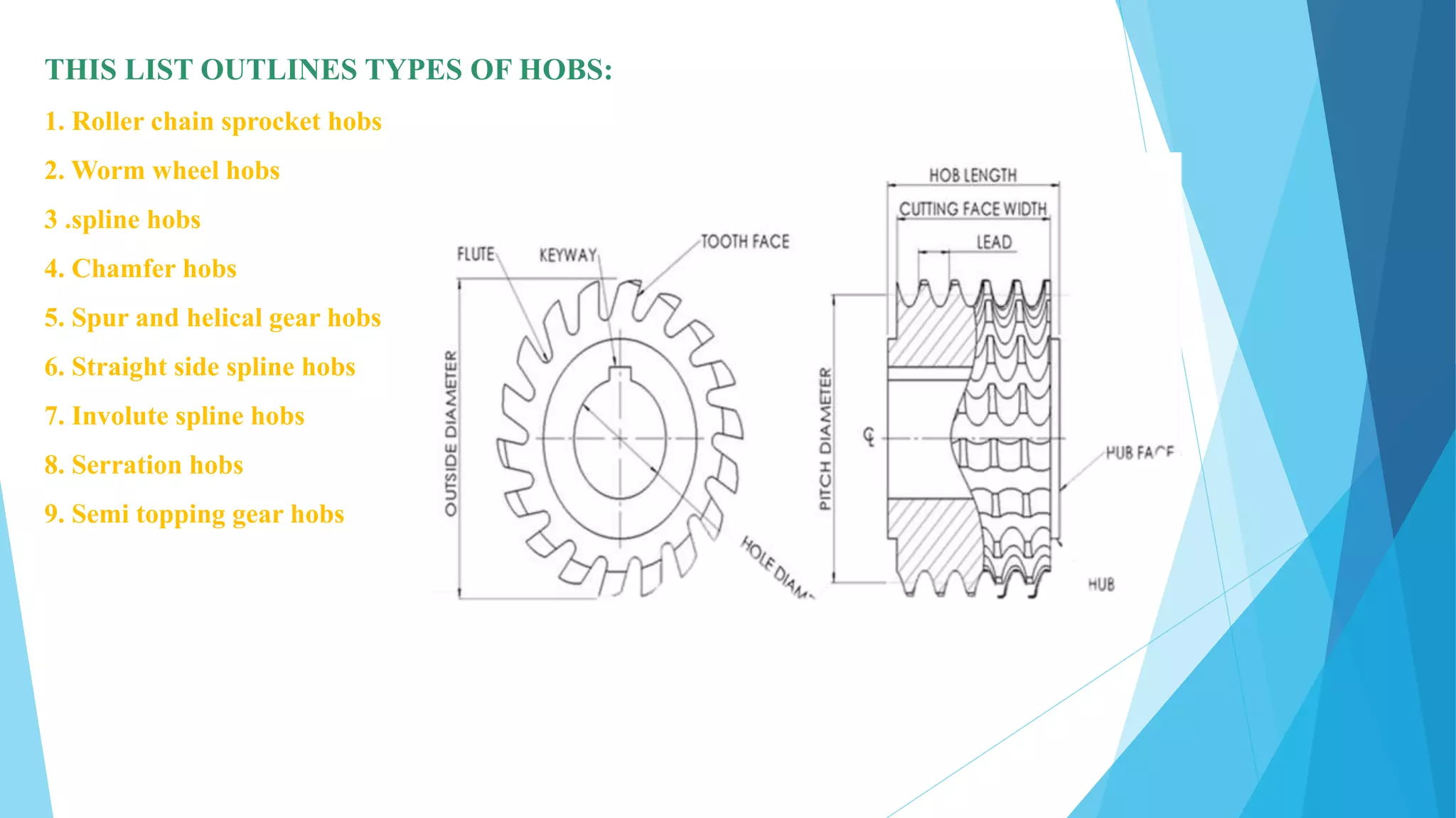
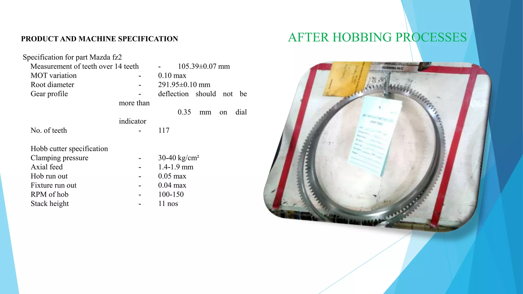
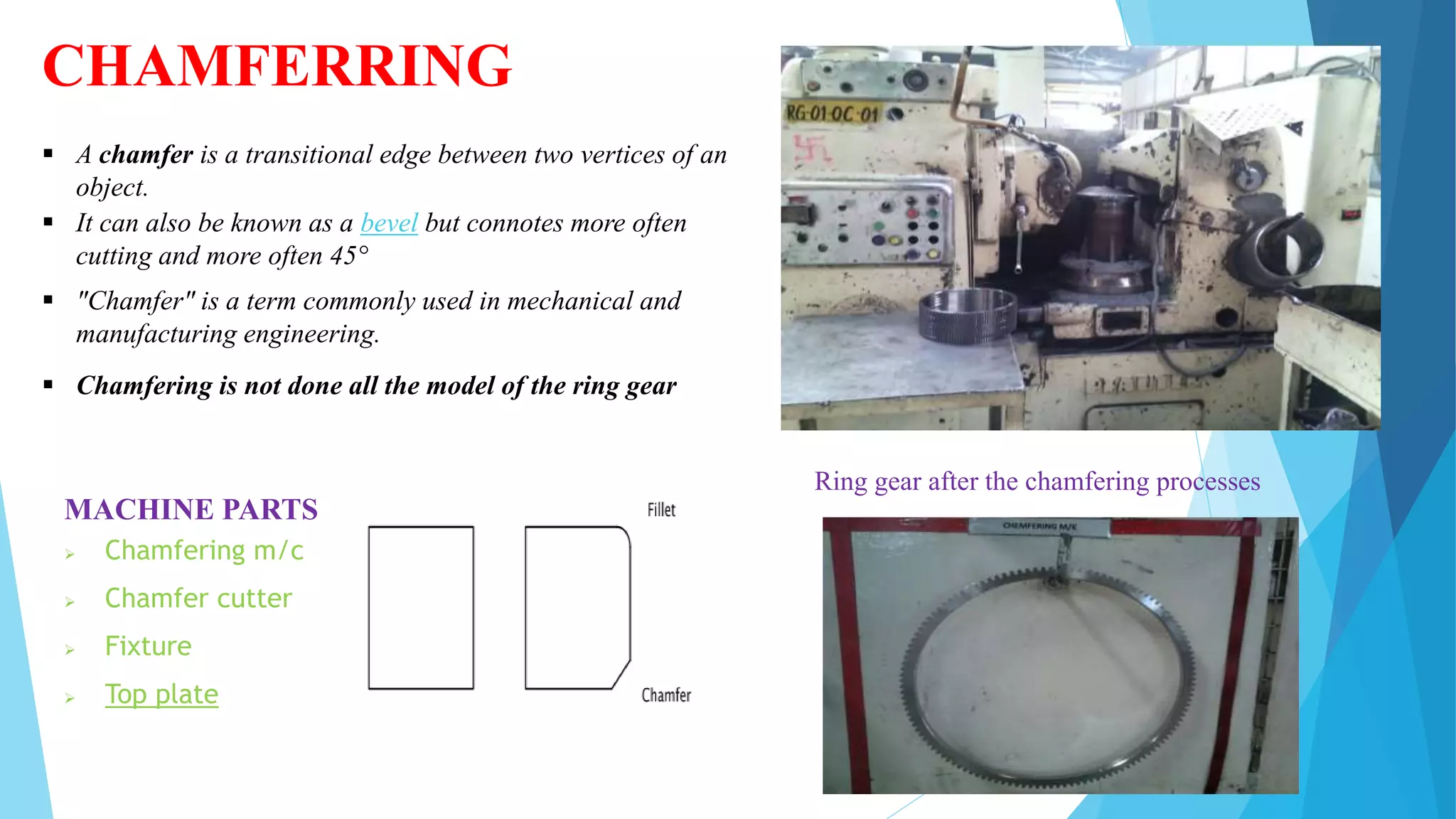
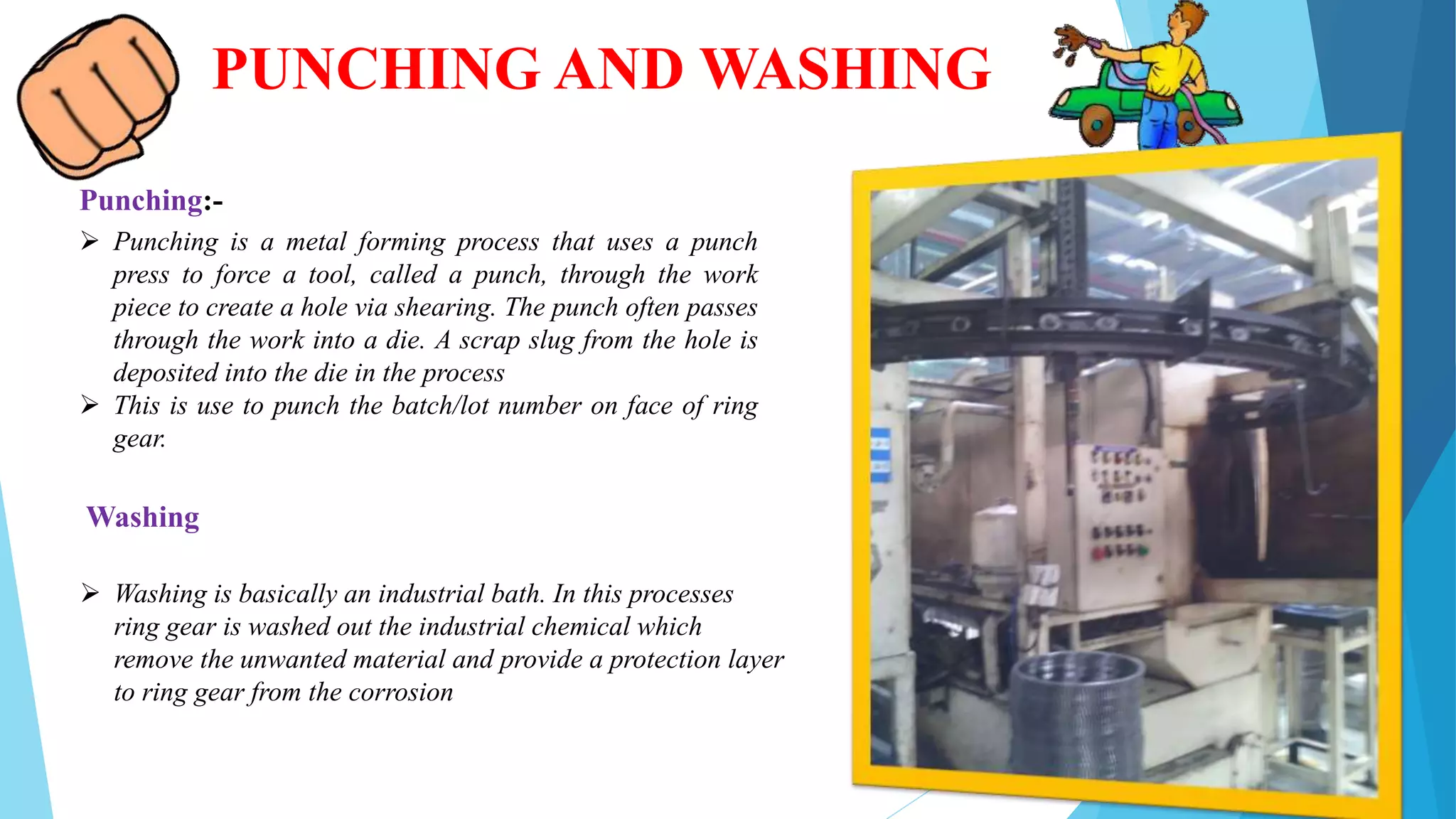
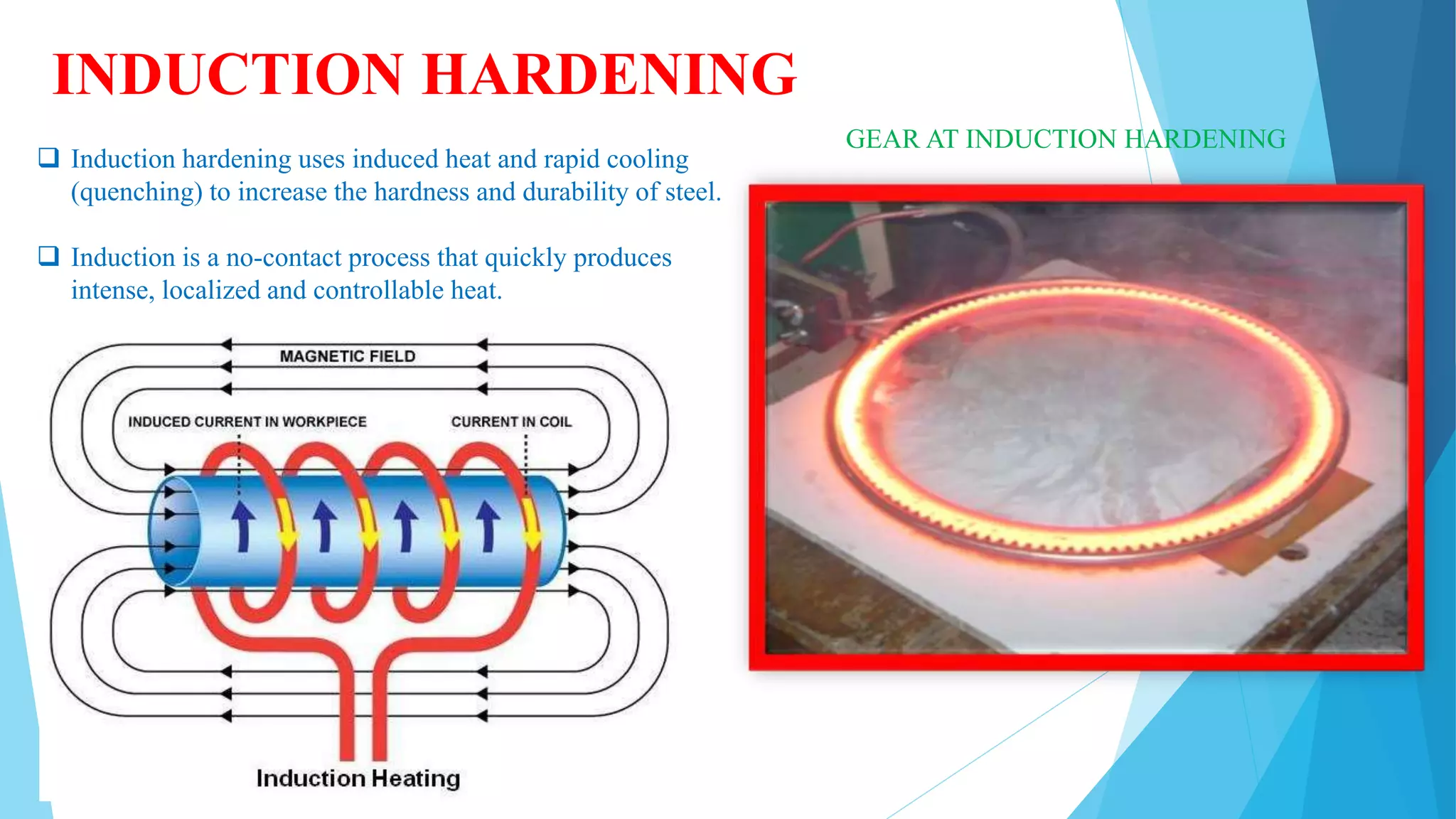
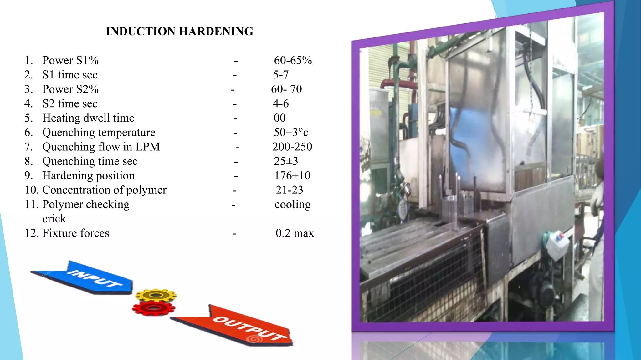
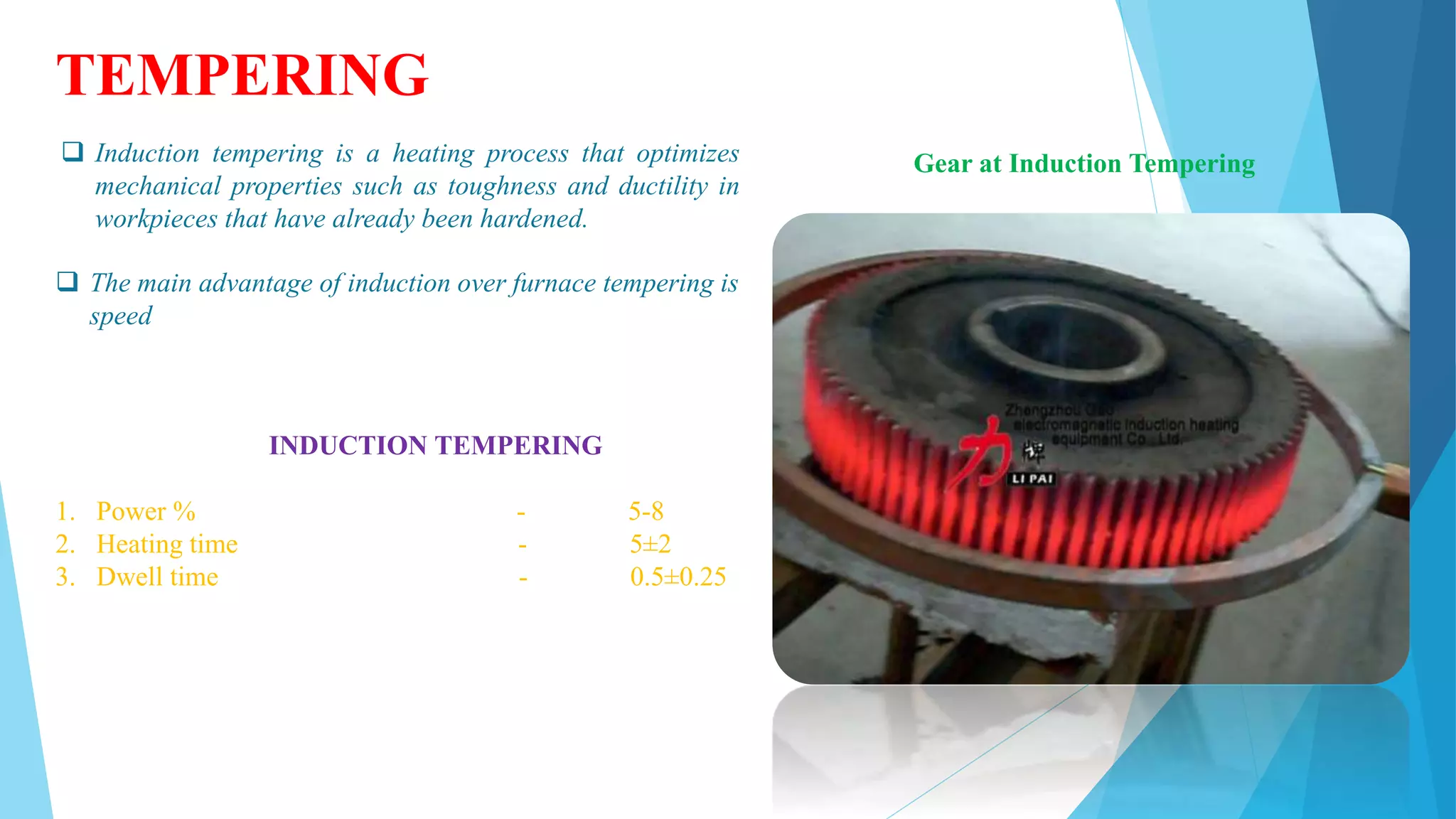
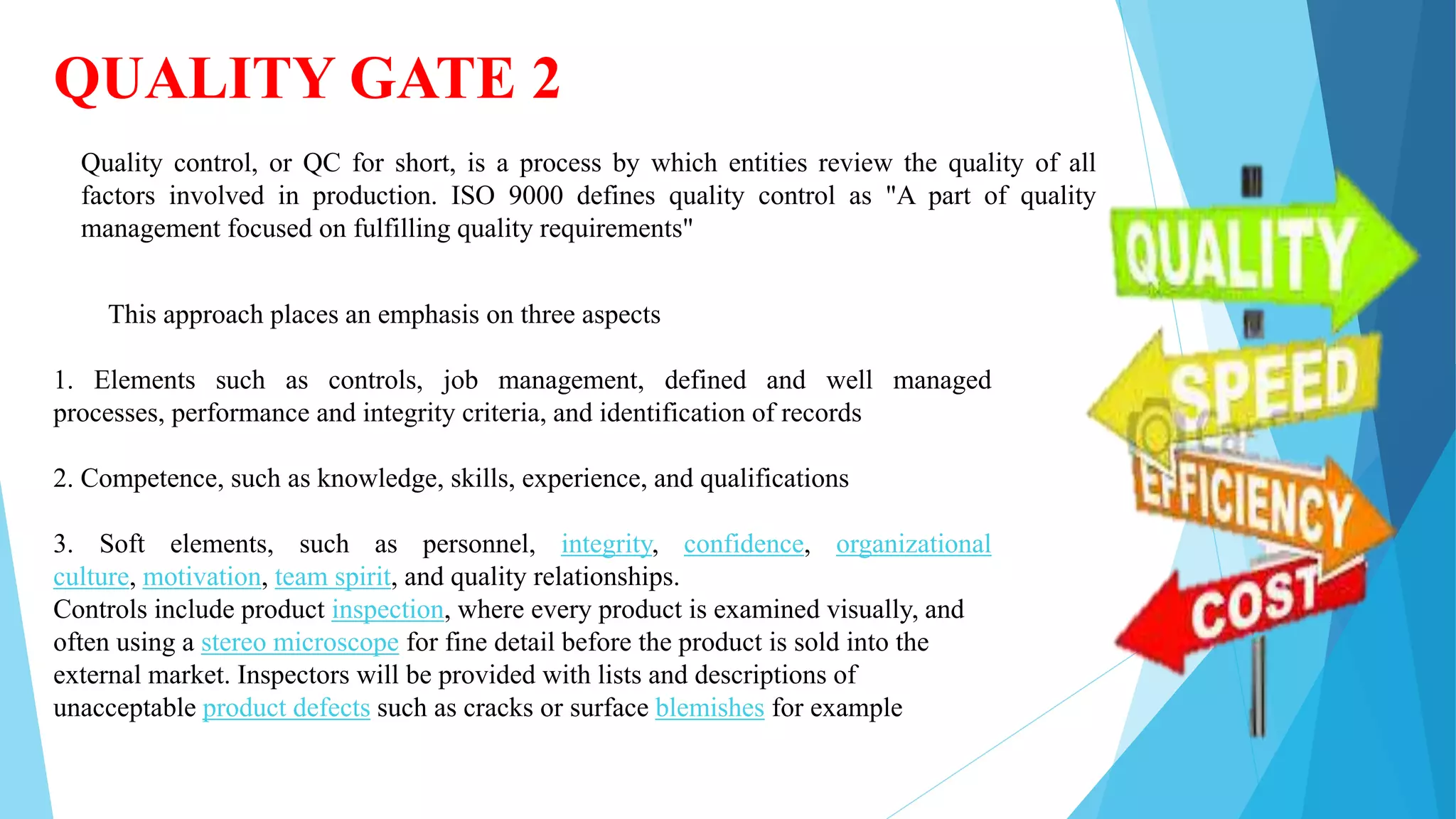
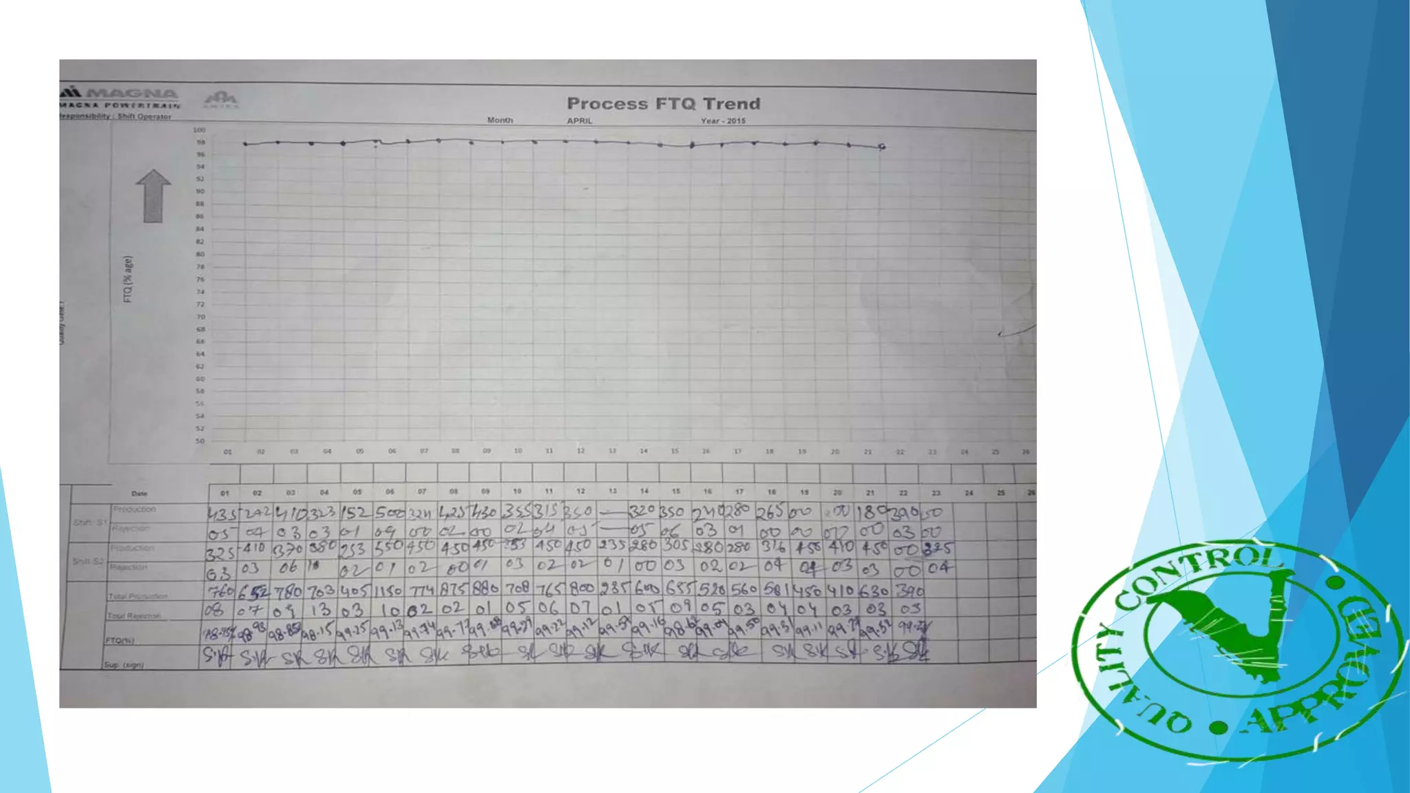
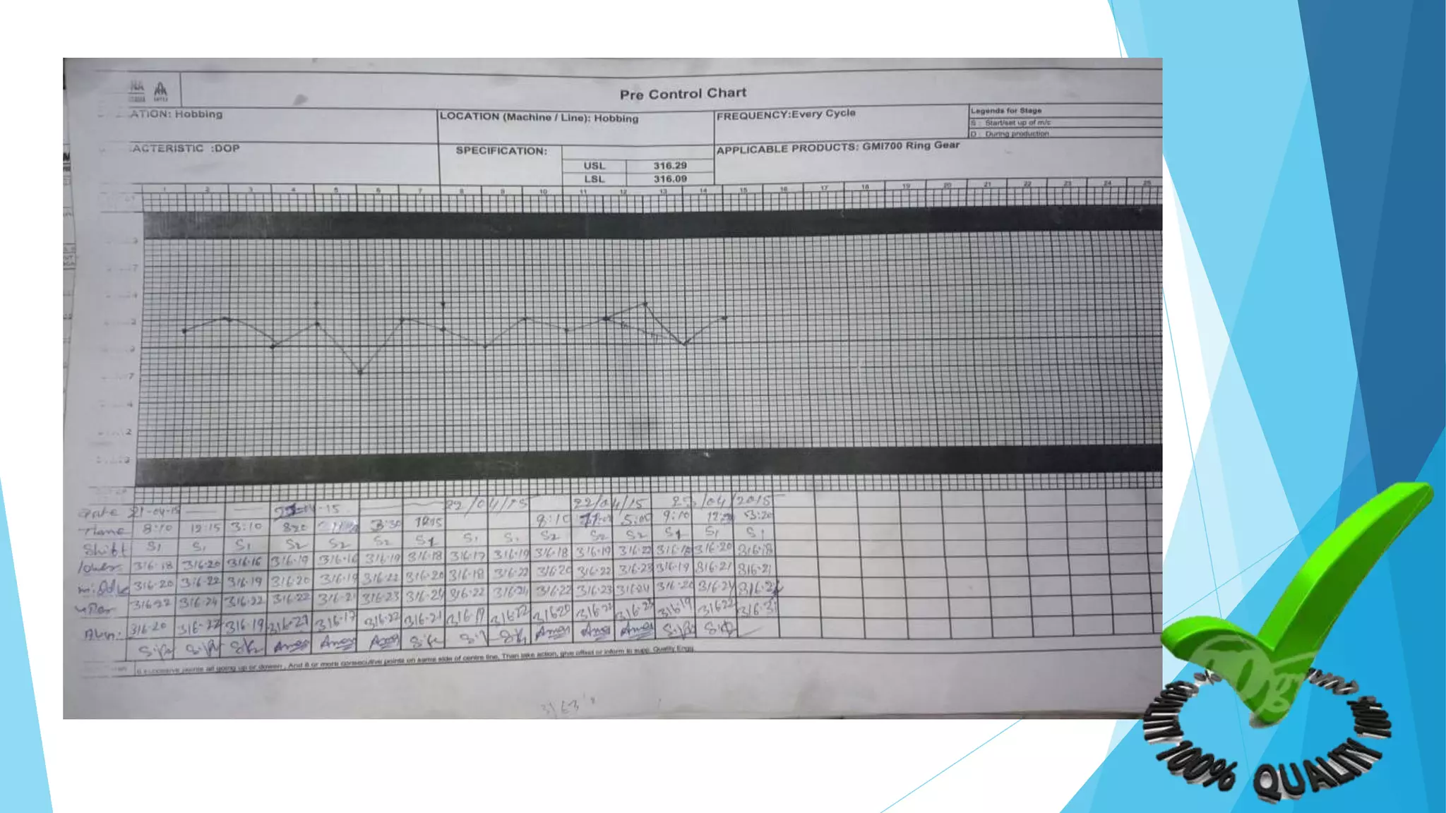


The document provides information about the ring gear production process at MPT Amtek Automotive Ltd. It describes the company's background and achievements. It then outlines the various manufacturing stages involved in producing ring gears, including bending, slitting, flash butt welding and trimming, normalizing, cold sizing, CNC machining, hobbing, chamfering, punching, washing, induction hardening, and tempering. Quality checks are conducted after key stages to ensure dimensional and geometric specifications are met.


