Downloaded 236 times
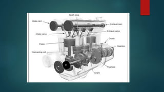
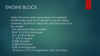
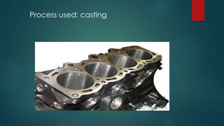


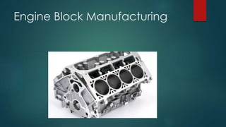


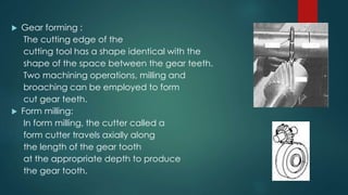

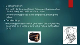
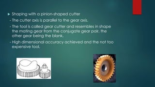
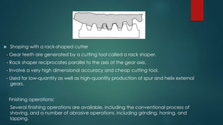
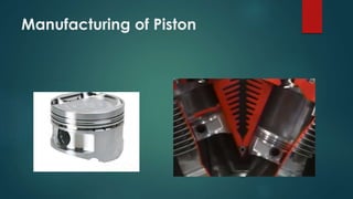


The document describes the manufacturing processes used to produce key engine components. Engine blocks are typically made of cast aluminum alloys using a casting process. Pistons are commonly forged from aluminum alloys and undergo machining like cutting, drilling, and milling. Crankshafts are usually made from steel alloys using casting and machining processes like turning, drilling, and grinding. Gears are manufactured through gear forming methods like milling and broaching or gear generation processes like hobbing and shaping.


![DESIGN AND FABRICATION OF THE IBM 90-90 SEAT BELT CLAMP KIA VEHICLE[1].pptx 2...](https://cdn.slidesharecdn.com/ss_thumbnails/designandfabricationoftheibm90-90seatbeltclampkiavehicle1-260116160442-70ff67fc-thumbnail.jpg?width=640&height=640&fit=bounds)


