Downloaded 861 times


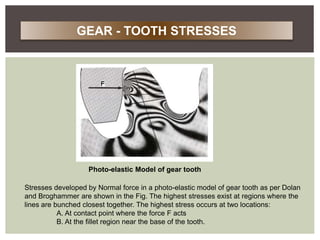


![At the section XX,
Mb= Pt x h
I= (1/12) b x t3
Y= t / 2
The bending stresses are given by,
σ b = Mb x y / I
= (pt x h)(t/2) / [(1/12)bt3]
Rearranging the terms,
Pt = b σ b (t2/6h)
Multiplying the numerator and denominator of the right-hand side by m,
Pt =m b σ b (t2/6hm)
BEAM STRENGTH OF GEAR TOOTH](https://image.slidesharecdn.com/spuregear-150221223946-conversion-gate01/85/Spure-gear-29-320.jpg)


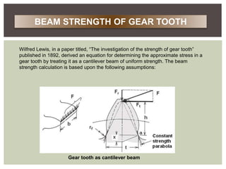
![When two cylinders are pressed together as shown in fig.(a), the contact stress is given
by,
σ c= 2*P/π*b*l ................(1.1)
and
b= { [ 2P(1-μ2)(1/E1 + 1/E2)] / π l(1/d1 + 1/d2) }1/2 ................(1.2)
where,
σ= maximum value of compressive stress (N/mm2)
P=force pressing the two cylinders together (N)
b= half width of deformation (mm)
l= axial length of the cylinder (mm)
d1,d2= diameter of two cylinders (mm)
E1,E2= moduli of elasticity of 2 cylinders (N/mm2)
μ = Poisson’s ratio
fig. contact stresses
WEAR STRENGTH OF GEAR TOOTH](https://image.slidesharecdn.com/spuregear-150221223946-conversion-gate01/85/Spure-gear-37-320.jpg)
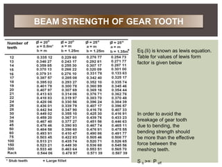
![Due to deformation under the action of load P, a rectangular surface of width (2b) and
length (l) is formed between the two cylinders. The elliptical stress distribution across the
width (2b) is shown in fig.
Substituting eq.(ii) into(i) and squaring both sides,
σc
2 =[1/π(1-μ2)]* (P/l)* {(1/r1+ 1/r2) / (1/E1+ 1/E2)} ................(1.3)
Where, r1,r2= radii of two cylinders
σc
2 =0.35*(P/l)* {(1/r1+ 1/r2) / (1/E1+ 1/E2)} ................(1.4)
The above equation of the contact stress is based on the following assumptions:
• The cylinders are made of isotropic materials.
• The elastic limit of the material is not exceeded.
• The dimensions r1,r2 are very large when compared to the width (2b) of the
deformation.
WEAR STRENGTH OF GEAR TOOTH](https://image.slidesharecdn.com/spuregear-150221223946-conversion-gate01/85/Spure-gear-38-320.jpg)

![r1,r2 are to be replaced by radii of curvature at the pitch point. Therefore,
r1= dp’ * sinα /2 r2= dg’ * sinα /2
There are some reasons for taking the radii of curvature at the pitch point.
• The wear on the gear tooth generally occurs at or near the pitch line.
• When only one pair of teeth carries the entire load, contact occurs at the pitch
point.
• The dynamic load is imposed on the gear tooth near the pitch line area.
(1/r1 + 1/r2)= 2/sinα [1/dp’ + 1/dg’] ............(1.5)
A ratio factor Q is defined as,
Q= 2*zg/(zg+zp) ..............(1.6)
WEAR STRENGTH OF GEAR TOOTH](https://image.slidesharecdn.com/spuregear-150221223946-conversion-gate01/85/Spure-gear-40-320.jpg)
![Substituting, dp’=m zp and dg’= m zg,
Q= 2 dg’/(dg’ + dp’)
Therefore,
[1/dp’ + 1/dg’] = (dg’ + dp’)/dg’ * dp’
= 2/ Q*dp’ ...............(1.7)
From eq.(v) and (vii),
(1/r1 + 1/r2)= 2/sinα*Q*dp’ ..............(1.8)
The force acting along the pitch line in fig.(b) is PN,
P=PN= Pt / cosα .............(1.9)
The axial length of the gears is the face width b,i.e. l=b
Therefore,
σc
2= 1.4*Pt / b*Q*dp’*sinα*cosα* (1/E1+ 1/E2) ............(1.10)
WEAR STRENGTH OF GEAR TOOTH](https://image.slidesharecdn.com/spuregear-150221223946-conversion-gate01/85/Spure-gear-41-320.jpg)


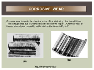
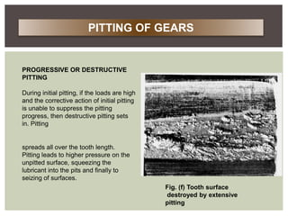
The document discusses various modes of gear failure, including abrasive wear, corrosive wear, pitting, and scoring. It provides detailed descriptions of these failures, their causes, and remedies, along with explanations of load and stress analysis methods for spur gear design. Additionally, it presents Lewis's equations for calculating bending and wear strength in gear teeth, emphasizing the importance of proper design to mitigate potential failures.


