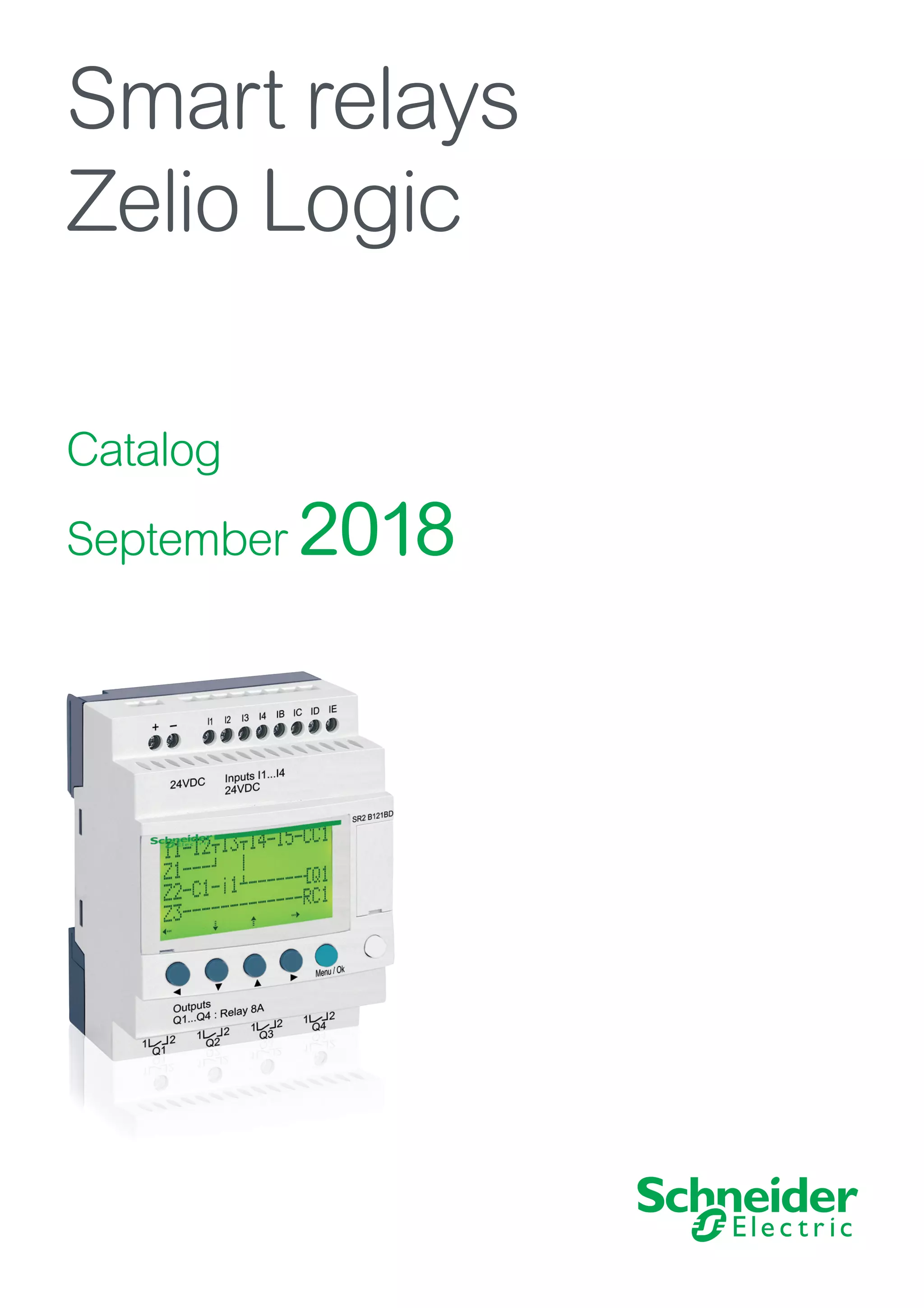
SlideShare a Scribd company logo
Catalog
September 2018
Smart relays
Zelio Logic
CÔNG TY CỔ PHẦN THIẾT BỊ ĐIỆN HOÀNG PHƯƠNG
ĐC: Số 10, ngõ 44, phố Võ Thị Sáu, P.Thanh Nhàn, Q.Hai Bà Trưng, TP. Hà Nội
MST: 0106798886
Tel: 024.3215.1322
Website: Hoangphuong.com.vn
Phone: 0944.240.317 / 0975.123.698 / 0961.008.858
Email: Codienhoangphuong@gmail.com
Quick access to Product information
Select your Catalog, your Training
With just 3 clicks, you can reach the 7,000 pages
of the Industrial Automation & Control catalog,
in both English and French.
–
– Digi-Cat is available on a USB key (for PC). To get your Digi-Cat, please
contact your local center
–
– Download Digi-Cat from this address:
http://digi-cat.schneider-electric.com/download.html
Find your training
–
– Find the right training for your needs
–
– Locate the training center with the selector tool, using this address:
http://www.schneider-electric.com/b2b/en/services/training/technical-training.jsp
then click on
1
Contents
Zelio Logic - Smart relays
General.  .  .  .  .  .  .  .  .  .  .  .  .  .  .  .  .  .  .  .  .  .  .  .  .  .  .  .  .  .  .  .  .  .  .  .  .  .  .  .  .  .  .  .  .  .  .  .  .  .  .  .  .  . page 2
Selection guides:
v
v Compact smart relays.................................................................................. page 4
v
v Modular smart relays and extensions.......................................................... page 6
b
b Compact and modular smart relays
v
v Presentation................................................................................................ page 8
v
v Functions
-
- Definitions............................................................................................ page 12
-
- Preset functions.................................................................................... page 13
-
- SFC (GRAFCET) function.................................................................... page 13
-
- Logic function....................................................................................... page 13
-
- Macro function...................................................................................... page 14
-
- PID function.......................................................................................... page 14
v
v Description
-
- Compact smart relays........................................................................... page 15
-
- Modular smart relays............................................................................ page 15
-
- Digital I/O extension module................................................................. page 15
v
v References
-
- Compact smart relays with display....................................................... page 16
-
- Modular smart relays............................................................................ page 18
-
- Digital I/O extension module................................................................. page 19
-
- Software............................................................................................... page 20
-
- Dedicated HMI...................................................................................... page 20
-
- Connection accessories....................................................................... page 20
-
- Memory cartridge................................................................................. page 20
-
- Mounting accessories........................................................................... page 21
b
b Communication
-
- Presentation......................................................................................... page 22
-
- Programming protocol description........................................................ page 23
v
v Communication protocol: Modbus serial link
-
- Presentation......................................................................................... page 24
-
- Connection examples........................................................................... page 25
-
- Functions.............................................................................................. page 26
-
- References........................................................................................... page 29
v
v Communication protocol: Ethernet Modbus/TCP
-
- Presentation, description...................................................................... page 27
-
- Functions.............................................................................................. page 28
-
- References........................................................................................... page 29
b
b Analogue I/O extension module
-
- Presentation, description...................................................................... page 30
-
- References........................................................................................... page 31
b
b Modem communication interface
-
- Presentation, description.........................................................pages 32 and 33
-
- Functions, Setting-up..............................................................pages 34 and 35
-
- References........................................................................................... page 35
Analogue interfaces
Selection guide .  .  .  .  .  .  .  .  .  .  .  .  .  .  .  .  .  .  .  .  .  .  .  .  .  .  .  .  .  .  .  .  .  .  .  .  .  .  .  .  .  .  .  .  .  . page 36
-
- Presentation......................................................................................... page 38
-
- References........................................................................................... page 40
Product reference index
b
b index......................................................................................................... page 42
2
General Zelio Logic - Smart relays
Smart relays for simple automation solutions
Designed for the management of simple automation systems, Zelio Logic smart
relays, with their unique combination of value for money and ease of use, provide a
real alternative to solutions based on cabled logic or specific cards.
Simple to select, install, and program, Zelio Logic is suitable for all your
applications.
Flexible, it offers you the choice of two ranges:
>
> Compact versions with fixed configurations
>
> Modular versions that allow the use of extension modules
with two programming languages (FBD or ladder).
Step into an intuitive world!
3
General Zelio Logic smart relays
Smart relays for simple automation solutions
>
> 2x more programming memory and more function blocks by simply updating
the firmware
>
> PID function for HVAC applications and 2G/3G modems
>
> Free software and firmware downloadable from the Schneider Electric
website
>
> Get to grips with software in less than an hour, simplified tool-free
programming in ladder or function block diagram (FBD) and SFC languages
for small applications
>
> Access to the ladder program and modification of settings on integrated
display
>
> Compact and modular smart relay range with expandable units
>
> Programmable logic: a smart alternative to cabled logic or specific cards
Zelio Logic
smart relay
>
> Modular
>
> With display
Zelio Logic I/O
extension modules
>
> Analog I/O
>
> Discrete I/O
Zelio Logic
smart relay
>
> Compact
>
> With or without
display
Zelio Logic
communication modules
>
> GSM/UMTS modem
>
> Modbus serial link
>
> Ethernet Modbus/TCP
Zelio Logic
communication
module
>
> GSM/UMTS modem
Monochrome HMI
The HMISTO501
Magelis Small Panel
is dedicated to
Zelio Logic smart relays:
3.4" monochrome touch
screen
+ Vijeo Designer
programming software
Color HMI
The HMISTO705
Magelis Small Panel
is dedicated to
Zelio Logic smart relays:
4.3” color touch screen
+ Vijeo XD
programming software
System components
Benefits
More flexibility - Easy design, maintenance, and
commissioning
Greater efficiency, less engineering time
Greater functionality
Higher performance
Zelio Soft 2
programming
software
4 3
Product type Compact smart relays
Supply voltage 24 V a 48 V a 100...240 V a 12 V c 24 V c
Number of I/O 12 20 20 10 12 20 12 20 10 12 20
Number of discrete inputs
(including analog inputs)
8 (0) 12 (0) 12 (0) 6 (0) 8 (0) 12 (0) 8 (4) 12 (6) 6 (0) 8 (4) 12 (2), 12 (6)
Number of “relay”/“transistor” outputs 4/0 8/0 8/0 4/0 4/0 8/0 4/0 8/0 4/0 4/0, 0/4 8/0, 0/8
With display, with clock
Programming language
SR2Bpp1B
FBD (1) or LADDER
_ SR2Bppp1FU
FBD (1) or LADDER
SR2Bpp1JD
FBD (1) or LADDER
SR2BpppBD
FBD (1) or LADDER
With display, without clock
Programming language
_ SR2A201E
LADDER only
SR2Appp1FU
LADDER only
_ SR2ApppBD
LADDER only
Without display, with clock
Programming language
SR2Epp1B
FBD (1) or LADDER
_ SR2Eppp1FU
FBD (1) or LADDER
_ SR2EpppBD
FBD (1) or LADDER
Without display, without clock
Programming language
_ _ SR2Dppp1FU
LADDER only
_ SR2DpppBD
LADDER only
Programming software (see page 20) “Zelio Soft 2” SR2SFT01 “Zelio Soft 2” SR2SFT01
Connection
accessories
(see page 20)
Serial link cable SR2CBL01 SR2CBL01
USB connecting cable SR2USB01 SR2USB01
Magelis terminal connecting
cable
SR2CBL08 for XBTN, XBTR, and XBTRT Magelis terminals
SR2CBL09 for HMISTO501 and HMISTO705 Magelis terminals
SR2CBL08 for XBTN, XBTR, and XBTRT Magelis terminals
SR2CBL09 for HMISTO501 and HMISTO705 Magelis terminals
Bluetooth interface SR2BTC01 SR2BTC01
Memory cartridge (see page 20) SR2MEM02
(dincompatible with SR2COM01)
SR2MEM02
(dincompatible with SR2COM01)
“Discovery” packs (see page 18) _ SR2PACKpFU _ SR2PACKpBD
Modem communication interface (see page 35) SR2COM01 SR2COM01 (for SR2B and SR2E) SR2COM01 SR2COM01 (for SR2B and SR2E)
GSM/UMTS modem (see page 35) SR2MOD02 SR2MOD02 SR2MOD02 SR2MOD02
Alarm management software (see page 35) “Zelio Logic Alarm” SR2SFT02 “Zelio Logic Alarm” SR2SFT02 “Zelio Logic Alarm” SR2SFT02 “Zelio Logic Alarm” SR2SFT02
Converters (thermocouple types J and K, Pt100 probes
and voltage/current)
_ _ RMppppBD: See Zelio Analog interfaces, page 38
Power supplies for DC control circuit – Please consult our catalog (n° DIA3ED2170401EN) and on our website www.schneider-electric.com
References SR2ppp1B SR2A201E SR2ppp1FU SR2Bpp1JD SR2ppppBD
Pages 16 and 17 16 16 and 17 16 16 and 17
(1)	FBD: Function Block Diagram
Selection guide Zelio Logic - Smart relays
Compact smart relays
5
6 3
Selection guide
Product type Modular smart relays
Supply voltage 24 V a 100...240 V a 12 V c 24 V c
Number of I/O 10 26 10 26 26 10 26
Number of discrete inputs
(including analog inputs)
6 (0) 16 (0) 6 (0) 16 (0) 16 (6) 6 (4) 16 (6)
Number of “relay”/“transistor” outputs 4/0 10/0 4/0 10/0 10/0 4/0, 0/4 10/0, 0/10
With display, with clock Yes Yes
Programming language FBD (1) or LADDER FBD (1) or LADDER
Programming software (see page 20) “Zelio Soft 2” SR2SFT01 “Zelio Soft 2” SR2SFT01
Connection
accessories
(see page 20)
Serial link cable SR2CBL01 SR2CBL01
USB connecting cable SR2USB01 SR2USB01
Magelis terminal
connecting cable
SR2CBL08 for XBTN, XBTR, and XBTRT Magelis terminals
SR2CBL09 for HMISTO501 and HMISTO705 Magelis terminals
SR2CBL08 for XBTN, XBTR, and XBTRT Magelis terminals
SR2CBL09 for HMISTO501 and HMISTO705 Magelis terminals
Bluetooth interface SR2BTC01 SR2BTC01
Memory cartridge (see page 20) SR2MEM02
(d incompatible with SR2COM01)
SR2MEM02
(d incompatible with SR2COM01)
“Discovery” packs (see page 18) _ SR3PACKpBD _ SR3PACKpBD
Modem communication interface (see page 35) SR2COM01 SR2COM01
GSM/UMTS modem (see page 35) SR2MOD02 SR2MOD02
Alarm management software (see page 35) “Zelio Logic Alarm” SR2SFT02 “Zelio Logic Alarm” SR2SFT02
Converters (thermocouple types J and K, Pt100 probes,
and voltage/current)
_ RMppppBD: See Zelio Analog interfaces, page 38
Power supplies for DC control circuit – Please consult our catalog (n° DIA3ED2170401EN) and on our website www.schneider-electric.com
References SR3Bpp1B SR3Bpp1FU SR3B261JD SR3BpppBD
Pages 18 18 18 18
Associated extensions Discrete I/O extensions Network communication extensions I/O extensions
Modbus serial link
(slave)
Ethernet port
(server)
Analog Discrete
or and or
Number of I/O 6 10 14 6 10 14 6 10 14 b
b Number of words:
v
v 4 (inputs)
v
v 4 (outputs)
v
v 4 (clock)
v
v 1 (status)
b
b Number of words:
v
v 4 (inputs)
v
v 4 (outputs)
v
v 4 (clock)
v
v 1 (status)
4 6 10 14
Type and number of discrete inputs
(or analog inputs)
4 (0) 6 (0) 8 (0) 4 (0) 6 (0) 8 (0) 4 (0) 6 (0) 8 (0) 0 (2) 4 (0) 6 (0) 8 (0)
Type and number of relay outputs
(or analog outputs)
2 (0) 4 (0) 6 (0) 2 (0) 4 (0) 6 (0) 2 (0) 4 (0) 6 (0) 0 (2) 2 (0) 4 (0) 6 (0)
References SR3XTpppB SR3XTpppFU SR3XTpppJD SR3MBU01BD SR3NET01BD SR3XT43BD SR3XTpppBD
Pages 19 19 29 31 19
(1) FBD: Function Block Diagram
Zelio Logic - Smart relays
Modular smart relays and extensions
7
8
Presentation
Zelio Logic smart relays are designed for use in small automated systems. They are
used in both the industrial and commercial sectors.
b
b For industry:
v
v automation of small finishing, production, assembly, or packaging machines
v
v small automated systems operating at 48 V a (hoisting application, etc.)
v
v decentralized automation of ancillary equipment for large and medium-sized
machines (in the textile, plastics, materials processing sectors, etc.)
v
v automation systems for agricultural machinery (irrigation, pumping, greenhouses,
etc.)
b
b For the commercial/building sectors:
v
v automation of barriers, roller shutters, access control
v
v automation of lighting systems
v
v automation of compressors and air conditioning systems
v
v etc.
Their compact size and ease of setup make them a competitive alternative to
solutions based on cabled logic or specific cards.
b
b Programming
Simple programming, backed up by the universal nature of the languages, meets the
requirements of automation specialists and the needs of electricians.
Programming can be performed:
v
v locally, using the buttons on the Zelio Logic smart relay (ladder language)
v
v on a PC using “Zelio Soft 2” software
When using a PC, programming can be performed either in ladder language or in
function block diagram (FBD) language (see page 10).
The LCD display unit backlight (1) is activated by pressing one of the 6 programming
buttons on the Zelio Logic smart relay or by programming with “Zelio Soft 2” software
(e.g. flashing when diagnosing a malfunction).
The clock has a lithium battery, which gives it an independent operating time of
10 years.
Data backup (preset values and current values) is provided by an EEPROM Flash
memory (with the same lifetime as the smart relay).
Compact smart relays
Compact smart relays meet requirements for simple automation systems.
The number of I/O can be:
b
b 12 or 20 I/O, supplied with 24 V a or 12 V c power
b
b 20 I/O, supplied with 48 V a power
b
b 10, 12, or 20 I/O, supplied with 100…240 V a or 24 V c power
Modular smart relays and extensions
The number of I/O for modular smart relays can be:
b
b 26 I/O, supplied with 12 V c power
b
b 10 or 26 I/O, supplied with 24 V a, 100…240 V a, or 24 V c power
To improve performance and flexibility, Zelio Logic modular smart relays can take
extensions to obtain a maximum of 40 I/O.
b
b Modbus serial link or Ethernet Modbus/TCP network communication extensions,
supplied with 24 V c power via the Zelio Logic smart relay at the same voltage
b
b analog I/O extension with 4 I/O, supplied with 24 V c power via the Zelio Logic
smart relay at the same voltage
b
b discrete I/O extensions with 6, 10, or 14 I/O, supplied with power via the
Zelio Logic smart relay at the same voltage
(1) LCD: Liquid crystal display
d Observe the order of assembly above when using a
Modbus slave or Ethernet server network communication
extension and a discrete or analog I/O extension.
An I/O extension cannot be inserted before a network
communication extension.
Presentation Zelio Logic - Smart relays
Compact and modular smart relays
Zelio Logic compact smart relay
Combination of modular smart relays and
extensions
1	 Modular Zelio Logic smart relay
(10 or 26 I/O)
2	 Discrete (6, 10, or 14 I/O) or
analog (4 I/O) I/O extension
1 2
1	 Modular Zelio Logic smart relay
(10 or 26 I/O)
2	 Modbus serial link or Ethernet Modbus/TCP
network communication extensions
3	 Discrete (6, 10, or 14 I/O) or
analog (4 I/O) I/O extension
1 2 3
Presentation
9
Communication
Cabled and wireless programming tools
b
b These programming tools allow the Zelio Logic smart relay to be connected to a
PC running “Zelio Soft 2” software:
v
v Cable connection:
-
- SR2USB01 cable to USB port
or
-
- SR2CBL01 cable to 9-way serial port
v
v Wireless link:
-
- SR2BTC01 Bluetooth interface
b
b Memory cartridge
The Zelio Logic smart relay can take a backup memory cartridge that allows the
application program to be copied to another Zelio Logic smart relay (it is only
possible to load and update the firmware with the SR2MEM02 memory cartridge).
The memory cartridge also enables a backup copy of the program to be saved prior
to replacing the product.
When used with a smart relay without display or buttons, the copy of the program
contained in the cartridge is automatically transferred to the Zelio Logic smart relay
on power-up.
Modbus serial link and Ethernet Modbus/TCP communication extensions
The Modbus serial link and Ethernet Modbus/TCP network communication
extension modules allow connection to automation system equipment such as
display units or PLCs (see page 22).
Modem communication interface
The “modem communication interface” offer in the Zelio Logic range includes:
-
- an SR2COM01 modem communication interface connected between a
Zelio Logic smart relay and a modem
-
- an SR2MOD02 GSM/UMTS (1) modem
-
- SR2SFT02 “Zelio Logic Alarm” software
This offer is designed for monitoring or remote control of machines or installations that
operate without personnel.
The modem communication interface, supplied with 12...24 V c power, enables
messages, phone numbers, and calling conditions to be stored (see page 32).
HMI terminals
HMISTO Small Panels offer added value to the equipment by enabling the creation of
eye-catching dialog screens.
They are available in monochrome (HMISTO501) or color (HMISTO705) versions.
They connect directly to the front panel of the smart relays in the memory cartridge
slot via the special cable (SR2CBL09).
The terminals are configured using Vijeo Designer (HMISTO501) or Vijeo XD
(HMISTO705) software. Exchanges with the smart relay are simplified using the
SLIn and SLout data exchange blocks in “Zelio Soft 2” (FBD language only).
24 words can be exchanged in each direction.
(1) Global System Mobile (2G)/Universal Mobile Telecommunications System (3G)
Presentation (continued) Zelio Logic - Smart relays
Compact and modular smart relays
Connecting cable Bluetooth interface
Memory cartridge
Ethernet Modbus/TCP
communication
extension
Modbus serial link
communication extension
Modem communication
interface
GSM/UMTS modem
Zelio Logic compact smart
relay + SR2CBL09 cable
HMISTO705 Small Panel
10
“Zelio Soft 2” for PC - version 5.1 (1)
“Zelio Soft 2” software enables:
b
b programming in ladder language or function block diagram (FBD) language
(see page 12)
b
b simulation, monitoring, and supervision
b
b uploading and downloading of programs
b
b print-out of customized files
b
b automatic program compilation
b
b online help
Consistency checks and application languages
“Zelio Soft 2” monitors applications by means of its consistency check function.
An indicator turns red at the slightest input error (ladder language). The problem can
be located simply by clicking the mouse.
“Zelio Soft 2” software allows users to switch between the 6 languages (English,
French, German, Italian, Portuguese, and Spanish) at any time and edit the
application file in the selected language.
Inputting messages for display on Zelio Logic
“Zelio Soft 2” software allows text function blocks to be configured, which can then
be displayed on Zelio Logic smart relays that have a display.
Program testing
2 test modes are provided:
b
b The simulation mode in “Zelio Soft 2” is used to test a program without a
Zelio Logic smart relay, i.e. to:
v
v enable discrete inputs
v
v display output status
v
v vary the voltage of the analog inputs
v
v enable the programming buttons
v
v simulate the application program in real time or in accelerated time
v
v display the different active program elements dynamically in red
b
b The monitoring is used to test the program executed by the smart relay, i.e. to:
v
v display the program “online”
v
v force inputs, outputs, auxiliary relays, and current function block values
v
v adjust the date and time
v
v switch from STOP mode to RUN mode and vice versa
In simulation or monitoring mode, the supervision window allows users to view the
status of the smart relay I/O within the application environment (diagram or image).
(1) These functions exist for versions u V 5.1.
Zelio Logic - Smart relays
Compact and modular smart relays
“Zelio Soft 2” programming software
Presentation
Programming in FBD language
Simulation mode
Monitoring window
11
User interfaces
“Zelio Soft 2” software (versions u 4.1) improves the ease of use of user interfaces
for the following functions:
“Split wiring sheet” function (ladder and FBD language)
The wiring sheet can be split into 2 to allow two separate parts of the wiring sheet to
be displayed on the same screen.
This can be used to:
b
b Display the required function blocks in the top and bottom parts of the screen
b
b Move the split bar as required
b
b Connect the function blocks between the 2 parts of the wiring sheet
The split wiring sheet is structured as follows:
1	 View of top part
2	 Top window vertical scroll bar
3	 Top window horizontal scroll bar
4	 Split bar
5	 View of bottom part
6	 Bottom window vertical scroll bar
7	 Bottom window horizontal scroll bar
“Replace function block” function (FBD language)
This function allows a block to be replaced without losing the input and output
connections.
E.g. replacing an “OR” block with a “NOR” block
zzzz
“Time Prog simulation” function (ladder and FBD languages)
Ladder or FBD program simulation mode allows the program to be debugged by
simulating it on the software workshop host computer.
A function allows the time on the simulator clock to be modified by setting it to 3 s
before the start of the next event .
The “Next event” button 1 is used to modify the simulator clock 2.
1
2
3
4
5
6
7
Structure of a split wiring sheet
1	 “OR” block to be replaced
1
2	 Move the links to the new “NOR”
block
2
3	 Delete the “OR” block and position
the “NOR” block in its place
3
“Acceleration and simulation terminals” window
2 1
Zelio Logic - Smart relays
Compact and modular smart relays
“Zelio Soft 2” programming software
Presentation (continued)
12
Ladder language
Definitions
Text function block
Up/down counter
Analog comparator
Auxiliary relay
LCD backlight
Output coil
Timer
Fast counter
Clock
Counter comparator
Daylight saving time change
Message
Ladder language enables a ladder program to be written with elementary functions,
elementary function blocks, and derived function blocks, as well as with contacts,
coils, and variables.
The contacts and coils can be annotated. Text can be placed freely within the
graphic.
b
b Ladder diagram input modes
“Zelio input” mode allows users who have programmed the Zelio Logic smart relay
directly on the device to achieve the same ease of use, even when using the
software for the first time.
“Ladder input” mode, which is more intuitive, is very user-friendly and incorporates
many additional features.
Two types of symbol can be used in ladder programming language:
v
v ladder symbols
v
v electrical symbols
“Ladder input” mode also allows the creation of mnemonics and comments
associated with each program line.
Instant switching from one input mode to the other is possible at any time, simply by
clicking the mouse.
Up to 240 (1) ladder diagram lines can be programmed, with 5 contacts and 1 coil
per program line.
b
b Functions
v
v 16 text function blocks
v
v 28 (1) timers, each of which can be configured from among 11 different types
(from 1/10 second to 9,999 hours)
v
v 28 (1) up/down counters from 0 to 32,767
v
v 1 fast counter (1 kHz)
v
v 16 analog comparators
v
v 8 clocks, each with 4 channels
v
v 56 (1) auxiliary relays
v
v 8 counter comparators
v
v LCD screen with programmable backlight
v
v automatic daylight saving time changeover
v
v variety of functions: coil, latching (Set/Reset), impulse relay, contactor
v
v 28 message blocks (with modem communication interface, see page 32)
Functions
Function Electrical scheme Ladder language Comment
Contact I corresponds to the real state of the contact wired to the smart
relay input.
i corresponds to the inverse state of the contact wired to the
smart relay input.
Standard coil The coil is energized when the contacts to which it is connected
are closed.
Latch coil (Set) The coil is energized (set) when the contacts to which it is
connected are closed.
It remains energized even if the contacts are no longer closed.
Unlatch coil
(Reset)
The coil is de-energized (reset) when the contacts to which it is
connected are closed.
It remains de-energized even if the contacts are no longer
closed.
(1) Possible using version V5.0 and above of “Zelio Soft 2” provided that the SR2COM01 communication module is not used. If this module is used, 16 timers,
16 counters, and 32 auxiliary relays are available and the program is limited to 120 ladder diagram lines.
13
14
22
21
or or
I
i
A1
A2
A1
A2
S
A1
A2
R
Zelio Logic - Smart relays
Compact and modular smart relays
“Zelio Soft 2” programming software
Presentation
13
Function block language (FBD/Grafcet SFC/logic functions) (1)
Definition
FBD language allows graphical programming based on the use of predefined function blocks, and provides the use of:
b
b 35 preprogrammed functions for counting, time delay, timing, switching threshold definition (e.g. temperature regulation), pulse generation,
time programming, multiplexing, and display
b
b 7 SFC functions
b
b 6 logic functions
Pre-programmed functions
Zelio Logic smart relays provide a high processing capacity, up to 500 (2) function blocks, including 35 pre-programmed functions:
TIMER AC TIMER BH TIMER Li TIMER BW TIMER AC
Timer. Function A/C
(ON-delay and OFF-delay)
Timer. Function BH
(adjustable pulsed signal)
Pulse generator
(ON-delay, OFF-delay)
Timer. Function BW
(pulse on rising/falling edge)
Timer. Function A/C with external
preset adjustment (ON-delay and
OFF-delay)
TIMER BH TIMER Li BISTABLE SET- RESET BOOLEAN
Timer. Function BH with
external preset adjustment
(adjustable pulsed signal)
Pulse generator with external
preset adjustment
(ON-delay, OFF-delay)
Impulse relay function Bistable latching - Priority
assigned either to SET or
RESET function
Allows logic equations to be
created between connected
inputs
CAM PRESET COUNT UP DOWN COUNT PRESET H-METER TIME PROG
Cam programmer Up/down counter Up/down counter with external
preset
Hour counter
(hour, minute preset)
Time programmer, weekly and
annual
GAIN TRIGGER MUX COMP IN ZONE ADD/SUB
Allows conversion of an
analog value by change of
scale and offset
Defines an activation zone
with hysteresis
Multiplexing functions on
2 analog values
Zone comparison
(Min. y Value y Max.)
Add and/or subtract function
MUL/DIV TEXT DISPLAY COM COMPARE
Multiply and/or divide function Display of digital and analog
data, date, time, messages for
Human-Machine interface
Display of digital and analog
data, date, time, messages for
Human-Machine interface
Sending of messages with
communication interface
(see page 32)
Comparison of 2 analog values
using the operands =, >, <, ≤, ≥, ≠
STATUS ARCHIVE SPEED COUNT CAN CNA
Access to smart relay status Storage of 2 values
simultaneously
Fast counting up to 1 kHz Analog-to-digital converter Digital-to-analog converter
SL In SL Out SUNTRACK SUNRISE/SUNSET PID
Input of a word via serial link Output of a word via serial link Tracks the sun’s position Outputs the sunrise and
sunset times
Temperature, level, flow rate,
or pressure control functions
SFC functions (3) (GRAFCET)
RESET-INIT INIT STEP STEP DIV-OR 2 CONV-OR 2
Reset initial step Initial step SFC step Divergence to OR Convergence to OR
DIV-AND 2 CONV-AND 2
Divergence to AND Convergence to AND
Logic functions
AND OR NAND NOR XOR NOT
AND function OR function NOTAND function NOT OR function Exclusive OR function NOT function
New feature for 2017
(1) Function block diagram
(2) Possible in version V5.0 or above of “Zelio Soft 2”
(3) Sequential function chart
Zelio Logic - Smart relays
Compact and modular smart relays
“Zelio Soft 2” programming software
Presentation (continued)
14
Function block language (FBD/Grafcet SFC/logic functions) (continued)
Macro function
3
Creating a macro
Inside a macro
1	 Select macro
2	 Edit properties
3	 Return to external view of a macro
4	 Internal function block in the macro
5	 Non-connected inputs
6	 Non-connected outputs
1 5 2 3 4 6 1 2
External view of a macro
1 Input connections
2 Output connection
3 Macro function block
A macro is a group of function blocks. It is
characterized by its number, name, links,
internal function blocks (255 max.), and its
I/O connections.
Seen from the outside, a macro behaves like a
function block with inputs and/or outputs likely
to be connected to links.
Once created, a macro can be manipulated like
a function block.
b
b Macro characteristics:
v
v The maximum number of macros is 64.
v
v A password dedicated to macros can be
used to protect their content.
v
v A macro can be edited/duplicated.
v
v A macro's comments can be edited.
b
b Macro properties:
A “Macro Properties” dialog box is used to
enter or modify the properties of a macro.
The properties of a macro are as follows:
v
v Macro name (optional)
v
v Block symbol, which may be:
-
- an identifier
-
- an image
v
v Name of inputs
v
v Name of outputs
PID function
Presentation
The PID function block is used to program
simple temperature, level, or pressure control
functions.
Two types of output enable adaptation to the
most common actuators available on the
market:
v
v Analog output, requiring the use of a
modular smart relay and an analog I/O
extension
v
v PWM output, enabling the integrated
outputs in any smart relay to be used.
Depending on the period set for PWM, and to
help extend service life, a smart relay equipped
with transistor outputs is recommended.
Programming
PID function blocks are available in FBD
language. To help with tuning, default
parameters are available for several typical
applications (flow, level, pressure,
temperature). These parameters can be
modified.
Tuning
The TEXT and DISPLAY function blocks are
used to help tune the control parameters
(Kp, Ti, Td) without using Zelio Soft 2: the
parameters can be modified directly using the
buttons on the front of the smart relay and the
display.
Zelio Logic - Smart relays
Compact and modular smart relays
“Zelio Soft 2” programming software
Functions (continued)
TEXT
TEXT
PID
PID
B000
B000
B003
B003
Tuning the parameters
Modifying parameters (Kp, Ti, Td) using the
programming and parameter setting buttons
Enable
Measure
Preset Setpoint
SetpointActivation
Analog Output
PWM Output
Kp
Ti
Td
Current Setpoint
PID
Programming the PID function
15
Compact smart relays
With display - 10, 12, and 20 I/O Without display - 10, 12, and 20 I/O
7
1
4
1
5
3
2
6
1
5
7
1 2 3 Zelio Logic compact smart relay front
panels comprise:
1	 Two retractable mounting feet
2	 Two power supply terminals
3	 Terminals for connecting the inputs
4	 Backlit LCD display with 4 lines of 18
characters
5	 Slot for memory cartridge or connection
to PC, modem communication interface,
HMI terminal (Magelis Small Panel), or
Bluetooth interface
6	 6 buttons for programming and
parameter entry
7	 Terminals for connecting the outputs
Modular smart relays
With display - 10 and 26 I/O
4
1
5
3
6 7
1 2 Zelio Logic modular smart relay front panels
comprise:
1	 Two retractable mounting feet
2	 Two power supply terminals
3	 Terminals for connecting the inputs
4	 Backlit LCD display with 4 lines of 18
characters
5	 Slot for memory cartridge or connection
to PC, modem communication interface,
HMI terminal (Magelis Small Panel), or
Bluetooth interface
6	 6 buttons for programming and
parameter entry
7	 Terminals for connecting the outputs
Discrete I/O extensions
6 discrete I/O 10 and 14 discrete I/O
1
2
1
5
5
4
3
1
1
5
5
4
3
2 Discrete I/O extension front panels
comprise:
1	 Two retractable mounting feet
2	 Terminals for connecting the inputs
3	 Terminals for connecting the outputs
4	 Connector for connection to the Zelio
Logic smart relay (powered via the Zelio
Logic smart relay)
5	 Locating pegs
Zelio Logic - Smart relays
Compact and modular smart relays
Description
16
Compact smart relays with display
Number
of I/O
Discrete
inputs
Including
0-10 V c
analog inputs
Relay
outputs
Transistor
outputs
Clock Reference Weight
kg
lb
24 V a power supply
12 8 0 4 0 Yes SR2B121B 0.250
0.551
20 12 0 8 0 Yes SR2B201B 0.380
0.838
48 V a power supply
20 12 0 8 0 No SR2A201E (1) 0.380
0.838
100...240 V a power supply
10 6 0 4 0 No SR2A101FU (1) 0.250
0.551
12 8 0 4 0 Yes SR2B121FU 0.250
0.551
20 12 0 8 0 No SR2A201FU (1) 0.380
0.838
Yes SR2B201FU 0.380
0.838
12 V c power supply
12 8 4 4 0 Yes SR2B121JD 0.250
0.551
20 12 6 8 0 Yes SR2B201JD 0.380
0.838
24 V c power supply
10 6 0 4 0 No SR2A101BD (1) 0.250
0.551
12 8 4 4 0 Yes SR2B121BD 0.250
0.551
0 4 Yes SR2B122BD 0.220
0.485
20 12 2 8 0 No SR2A201BD (1) 0.380
0.838
6 8 0 Yes SR2B201BD 0.380
0.838
0 8 Yes SR2B202BD 0.280
0.617
“Zelio Soft 2” software
See page 20
Connection accessories
See page 20
Compact “discovery” packs
Pack contents:
Compact smart relay with display SR2Bppppp
+ “Zelio Soft 2” programming software on CD-ROM SR2SFT01
+ PC connecting cable SR2USB01
Number of I/O Pack contents
(references)
Reference Weight
kg
lb
100...240 V a power supply
12 SR2B121FU
+ SR2SFT01
+ SR2USB01
SR2PACKFU 0.700
1.543
20 SR2B201FU
+ SR2SFT01
+ SR2USB01
SR2PACK2FU 0.850
1.874
24 V c power supply
12 SR2B121BD
+ SR2SFT01
+ SR2USB01
SR2PACKBD 0.700
1.543
20 SR2B201BD
+ SR2SFT01
+ SR2USB01
SR2PACK2BD 0.700
1.543
Modem communication interface
12...24 V c power supply
Description Reference
Modem communication interface See page 32
(1) Programming in ladder language only
SR2A201BD
SR2SFT01
Zelio Logic - Smart relays
Compact smart relays
References
Modem communication interface
SR2PACKppp
17
Compact smart relays without display
Number
of I/O
Discrete
inputs
Including
0-10 V c
analog
inputs
Relay
outputs
Transistor
outputs
Clock Reference Weight
kg
lb
24 V a power supply
12 8 0 4 0 Yes SR2E121B 0.220
0.485
20 12 0 8 0 Yes SR2E201B 0.350
0.772
100...240 V a power supply
10 6 0 4 0 No SR2D101FU (1) 0.220
0.485
12 8 0 4 0 Yes SR2E121FU 0.220
0.485
20 12 0 8 0 No SR2D201FU (1) 0.350
0.772
Yes SR2E201FU 0.350
0.772
24 V c power supply
10 6 0 4 0 No SR2D101BD (1) 0.220
0.485
12 8 4 4 0 Yes SR2E121BD 0.220
0.485
20 12 2 8 0 No SR2D201BD (1) 0.350
0.772
6 8 0 Yes SR2E201BD 0.350
0.772
“Zelio Soft 2” software
See page 20
Accessories
See page 20
Modem communication interface
12...24 V c power supply
Description Reference
Modem communication interface See page 32
(1) Programming in ladder language only
Zelio Logic - Smart relays
Compact smart relays
References (continued)
SR2E121BD
SR2USB01
Modem communication interface
SR2SFT01
18
Modular smart relays with display
Number
of I/O
Discrete
inputs
Including
0-10 V c
analog
inputs
Relay
outputs
Transistor
outputs
Clock Reference Weight
kg
lb
24 V a power supply
10 6 0 4 0 Yes SR3B101B 0.250
0.551
26 16 0 10 (1) 0 Yes SR3B261B 0.400
0.882
100...240 V a power supply
10 6 0 4 0 Yes SR3B101FU 0.250
0.551
26 16 0 10 (1) 0 Yes SR3B261FU 0.400
0.882
12 V c power supply
26 16 6 10 (1) 0 Yes SR3B261JD 0.400
0.882
24 V c power supply
10 6 4 4 0 Yes SR3B101BD 0.250
0.551
0 4 Yes SR3B102BD 0.220
0.485
26 16 6 10 (1) 0 Yes SR3B261BD 0.400
0.882
0 10 Yes SR3B262BD 0.300
0.661
“Zelio Soft 2” software
See page 20.
Connection accessories
See page 20.
Modular “discovery” packs
Pack contents:
Modular smart relay with display SR3Bpppp
+ “Zelio Soft 2” programming software on CD-ROM SR2SFT01
+ PC connecting cable SR2USB01
Number of I/O Pack contents
(references)
Reference Weight
kg
lb
100...240 V a power supply
10 SR3B101FU
+ SR2SFT01
+ SR2USB01
SR3PACKFU 0.700
1.543
26 SR3B261FU
+ SR2SFT01
+ SR2USB01
SR3PACK2FU 0.850
1.874
24 V c power supply
10 SR3B101BD
+ SR2SFT01
+ SR2USB01
SR3PACKBD 0.700
1.543
26 SR3B261BD
+ SR2SFT01
+ SR2USB01
SR3PACK2BD 0.850
1.874
(1) Including 8 outputs at maximum current of 8 A and 2 outputs at maximum current of 5 A.
Note: The Zelio Logic smart relay and its associated extensions have an identical voltage to be
able to operate together.
SR3B261B
SR2SFT01
SR3PACKppp
Zelio Logic - Smart relays
Modular smart relays
References
19
Zelio Logic - Smart relays
Modular smart relays
References (continued)
Communication extension (1)
24 V c power supply (via SR3B...BD smart relays)
For use with Communication ports Reference
SR3Bpp1BD and SR3Bpp2BD
Zelio Logic modular smart
relays
Modbus RS485 serial link
(RJ45)
See page 22
Ethernet Modbus/TCP (RJ45) See page 22
Analog I/O extension (2)
24 V c power supply (via Zelio Logic SR3B...BD smart relay)
Number
of I/O
Inputs Including c Including
Pt100
0-10 V c
output
Reference
0-10 V 0-20 mA
4 2 2 max. 2 max. 1 max. 2 See page 30
Discrete I/O extensions
Number
of I/O
Discrete inputs Relay outputs Reference Weight
kg
lb
24 V a power supply (via Zelio Logic SR3BpppB smart relays)
6 4 2 SR3XT61B 0.125
0.276
10 6 4 SR3XT101B 0.200
0.441
14 8 6 (3) SR3XT141B 0.220
0.485
100-240 V a power supply (via Zelio Logic SR3BpppFU smart relays)
6 4 2 SR3XT61FU 0.125
0.276
10 6 4 SR3XT101FU 0.200
0.441
14 8 6 (3) SR3XT141FU 0.220
0.485
12 V c power (via Zelio Logic SR3B261JD smart relay)
6 4 2 SR3XT61JD 0.125
0.276
10 6 4 SR3XT101JD 0.200
0.441
14 8 6 (3) SR3XT141JD 0.220
0.485
24 V c power supply (via Zelio Logic SR3BpppBD smart relays)
6 4 2 SR3XT61BD 0.125
0.276
10 6 4 SR3XT101BD 0.200
0.441
14 8 6 (3) SR3XT141BD 0.220
0.485
Modem communication interface (4)
12...24 V c power supply
Description Reference
Modem communication interface See page 32
(1) See page 22.
(2) See page 30.
(3) Including 4 outputs at maximum current of 8 A and 2 outputs at maximum current of 5 A.
(4)See page 32.
Note: The Zelio Logic smart relay and its associated extensions have an identical voltage to be
able to operate together.
Ethernet Modbus/TCP
communication extension
Modbus serial link
communication extension
SR3XT141JD
Modem communication interface
20
Zelio Logic - Smart relays
Compact and modular smart relays
References (continued)
Programming
Description Use Reference Weight
kg
lb
“Zelio Soft 2” software
Programming software
“Zelio Soft 2”, multilingual,
supplied on CD-ROM (1)
For PC and 32-bit and 64-bit operating systems compatible with
Windows 7, 8.1, and 10
SR2SFT01 0.200
0.441
HMI
Magelis Small Panel
with monochrome
touch screen
3.4” monochrome screen with 3 colors (green, orange, red)
16 MB application memory capacity
Programmed using Vijeo Designer u V6.0
HMISTO501 0.200
0.441
Magelis Small Panel
with color TFT
touch screen
4.3” color screen
26 MB application memory capacity
Programmed using Vijeo XD
HMISTO705 (2) 0.220/
0.485
Connection accessories
Connecting cables
Length: 3 m (9.84 ft.)
For use with “Zelio Soft 2”
Between the PC (9-way SUB-D connector) and the Zelio Logic
smart relay (programming port connector)
SR2CBL01 0.150
0.331
Between the PC (USB connector) and the Zelio Logic smart relay
(programming port connector)
SR2USB01 0.100
0.220
Connecting cables
Length: 2.5 m (8.20 ft.)
Between the Magelis XBTN, XBTR, or XBTRT Small Panel
(8-way mini-DIN connector) and the Zelio Logic smart relay
(programming port connector)
SR2CBL08 0.100
0.220
Between the Magelis HMISTO501 or HMISTO705 Small Panel
(9-way removable screw terminal block) and the Zelio Logic smart
relays (programming port connector)
SR2CBL09 -
Bluetooth interface for
Zelio Logic smart relays
Between the PC (wireless link) and the Zelio Logic smart relay.
Range of 10 m (32.80 ft.) (class 2)
SR2BTC01 0.015
0.033
Memory cartridges (3)
EEPROM memory
cartridges
For firmware (software embedded in the smart relay)
version y 2.4
SR2MEM01 0.010
0.022
For firmware (software embedded in the smart relay)
version u 3.0
SR2MEM02 0.010
0.022
Online documentation available
User Manuals for direct programming on the Zelio Logic smart relay (in English, French, German, Italian, Portuguese, or Spanish):
please visit our website www.schneider-electric.com.
Regulated switch mode power supplies
Input voltage Nominal output voltage Reference
100...240 V a (50/60 Hz) 5 V c, 12 V c, or 24 V c Please refer to the product
catalog (DIA3ED2170401EN)
and visit our website
www.schneider-electric.com
Converters
Description Reference
Converters for J and K type thermocouples,
for Pt100 probes, and voltage/current
See page 38
(1) Also available as a free download from www.schneider-electric.com.
(2) The SR2CBL09 cable used to connect an HMISTO705 terminal to a smart relay must be equipped with a shunt between the
terminals marked CTS and RTS. This shunt is included on all cables leaving the factory after June 2017 (date code 1722).
(3) The use of memory cartridge SR2MEM02 to load the program is not compatible with the SR2COM01 modem communication
interface.
PA577329
HMISTO501
HMISTO705
PF153902B
SR2USB01
SR_531_CPFJR16063
SR2BTC01
SR_531_CPFJR16058B
SR2MEM02
SR_531_CPFJR16068
SR_531_CPFJR16062B
SR2CBL09
SR2SFT01
SR_531_CPFJR16066B-14108
21
Mounting accessories
Description/use Mounting capacity Reference Weight
kg
lb
Dust- and damp-proof
enclosure with split
blanking plate
arrangement, equipped
with an IP 55 dust- and
damp-proof window with
hinged flap for mounting
through a door
-	 1 or 2 SR2 smart relays with
10 or 12 I/O
-	 or 1 SR2 smart relay with 20 I/O
-	 or 1 SR3 smart relay with 10 I/O +
1 I/O extension with 6, 10, or 14 I/O
-	 or 1 SR3 smart relay with 26 I/O +
1 I/O extension with 6 I/O
14210 0.350
0.772
Mounting bracket
and symmetrical
mounting rail
For mounting enclosure 14210
through a door panel
14211 0.210
0.463
14210
14211
References (continued) Zelio Logic - Smart relays
Compact and modular smart relays
22
Presentation Zelio Logic - Smart relays
Communication
Presentation
In order to communicate with their environment, Zelio Logic compact and modular
smart relays and their extensions are equipped with various types of communication
port.
b
b Compact and modular smart relays feature 1 serial link port for connecting a PC, the
modem communication interface, a memory cartridge slot, or an HMI terminal. This
port uses a dedicated Zelio Logic communication protocol.
b
b Zelio Logic modular smart relay extensions feature:
v
v 1 RS 485 serial link port using the Modbus protocol on the SR3MBU01BD extension
v
v 1 Ethernet Modbus/TCP 10/100 base T port on the SR3NET01BD extension
6 7
SR_531_OPFJR16089
2
1 3
4
5
1 	 Modular smart relay (10 or 26 I/O)
2 	 Serial link port, Zelio Logic connector
3 	 Modbus slave or Ethernet server communication extension module
4 	 RJ45 connector for Modbus serial link or Ethernet Modbus/TCP network
connection
5 	 Discrete (6, 10, or 14 I/O) or analog (4 I/O) I/O extension
6 	 Modem communication interface
7 	 GSM/UMTS modem
d Observe the order of assembly above when using a Modbus serial link (slave) or Ethernet
Modbus/TCP (server) network communication extension and a discrete or analog I/O extension.
An I/O extension cannot be inserted before the Modbus serial link (slave) or Ethernet Modbus/
TCP (server) network communication extension.
Communication ports on Zelio Logic smart relays and their extensions
Smart
relays
Smart relay serial
link port
Modbus serial
link port on
SR3MBU01BD
extension
Ethernet
Modbus/TCP port
on SR3NET01BD
extension
Modem
communication
interface port
Physical layer
Proprietary RS 485 10/100 base T RS 232
Connector
Zelio Logic RJ45 RJ45 Dedicated Zelio
Compact All types
(connection and
isolation via
SR2CBL01 or
SR2USB01 cable)
– – All SR2Bppppp,
SR2Eppppp smart
relays with clock
(see page 32)
Modular All types
(connection and
isolation via
SR2CBL01 or
SR2USB01 cable)
All SR3BpppBD
smart relays
with 24 V c 
power supply
All SR3BpppBD
smart relays
with 24 V c 
power supply
All types (see page
32)
23
Description Zelio Logic - Smart relays
Communication
Description
Wired connection
1
3
2
1 	 Programming PC
2 	 USB cable (SR2USB01) or serial link cable
(SR2CBL01) (1)
3 	 Zelio Logic compact or modular smart relay
Wireless connection
4
5
6
4 	 Programming PC with integrated Bluetooth technology
(1)
5 	 Bluetooth interface (SR2BTC01) for Zelio Logic smart
relay (1)
6 	 Zelio Logic compact or modular smart relay
Modem link
7
10
9
11
10
13
8
12
7 	 PC-modem connecting cable (SR1CBL03)
8 	 Programming PC
9 	 Modem interface connecting cable included with
SR2COM01(1)
10 	Data transmission/reception modem (SR2MOD02) (1)
11 	Phone or radio link
12 	Communication interface (SR2COM01)
13 	Zelio Logic compact or modular smart relay
(1) See page 20.
24
Presentation,
description
Zelio Logic - Smart relays
Communication
Modbus serial link communication protocol
Presentation
The Modbus communication protocol is the master/slave type.
Two exchange methods are possible:
b
b Request/response:
-
- The request from the master is addressed to a specific slave.
-
- The response is expected by return from the polled slave.
b
b Broadcast:
-
- The master broadcasts a request to all slave stations on the bus. These
stations execute the command without transmitting a response.
Zelio Logic modular smart relays are connected to the Modbus network via the
Modbus slave network communication extension. This extension is a slave that is
not electrically isolated.
The Modbus slave network communication extension must be connected to an
SR3BpppBD modular smart relay with a 24 V c power supply.
Configuration
The Modbus slave network communication extension can be configured:
b
b locally, using the buttons on the smart relay (1)
b
b on a PC using “Zelio Soft 2” software (see page 10)
When using a PC, programming can be performed either in ladder language or in
function block diagram (FBD) language (see page 12).
Description
6 1
8
8
2
5
3
4
1
7
The Modbus slave network communication
extension SR3MBU01BD comprises:
1 	 Two retractable mounting lugs
2 	 A Modbus network connection
(RJ45 shielded female connector)
3 	 A communication LED (COM)
4 	 A power LED (PWR)
5 	 A screw terminal block for the protective
ground connection
6 	 Spring for clip-on mounting on a
35 mm/1.38 in rail
7 	 Connector for connection to the
Zelio Logic smart relay (powered via
the Zelio Logic smart relay)
8 	 Locating pegs
(1) Programming via the buttons on the front panel of the smart relay is only possible in ladder
language.
SR_531_CPFJR16052
Modbus serial link network communication extension
25
Description Zelio Logic - Smart relays
Communication
Modbus serial link communication protocol
Connection examples
Example 1
- Total length of cables between M221 and Altivar 12: y 30 m (98.43 ft)
- Length of cable 3: y 10 m (32.81 ft)
Line polarization active Line terminator
3
4
4
3
2
5 7 7 8
6 6
1
b b
c 5 V
3
1 	 Slave display unit XBTN401
2 	 Controller to Magelis HMI cordsets
3 	 Modbus RS485 cordsets (VW3A8306Rpp extension cables)
4 	 Junction box TWDXCAT3RJ (1 x RJ45 for trunk cable, 2 x RJ45 for drop)
5 	 Modicon master logic controller TM221Cppp equipped with communication
cartridge TMC2SL1 (1)
6 	 Modular smart relay SR3BpppBD
7 	 Modbus communication extension module SR3MBU01BD
8 	 Altivar 12 drive
(1) Polarization must be enabled in the Modicon M221 master.
Example 2
- Total length of cables between isolation boxes 4: y 1,000 m (3,281 ft.)
- Length of drop cables 3: y 10 m (32.81 ft.)
Line polarization active Line terminator
4
3
3
4 (1)
3
3
2
1
5
10
6 8 8 9
9
7
4 (1)
1 	Master display unit HMISCU
2 	Controller to Magelis HMI cordsets
3 	Modbus RS485 cordsets (VW3A8306Rpp extension cables)
4 	Serial link tap isolation box TWDXCAISO (1 x RJ45 for trunk cable, 2 x RJ45 for
drop)
5 	Modicon master logic controller TM221Mppp (2)
6 	Altivar 312 variable speed drive
7 	TeSys U motor starter controller
8 	Modular smart relay SR3BpppBD
9 	Modbus communication extension module SR3MBU01BD
10 	Power meter IEM31
(1) Box powered by the logic controller
(2) Network master connected to serial link port (SERIAL1)
Function description
b
b The Modbus slave network communication extension is connected to a 2-wire or
4-wire Modbus network (1).
b
b The maximum length between 2 TWDXCAISO taps configured as line terminators
is 1,000 m/3,281 ft (9600 baud max., AWG 26).
b
b Amaximum of 32 slaves can be connected to the Modbus network, or a maximum of
247 slaves with repeaters.
b
b The connection cable and its RJ45 male connectors must be shielded.
b
b The module t terminal must be connected directly to the protective ground.
(1) Refer to the Quick Reference Guide supplied with the product.
26
Functions Zelio Logic - Smart relays
Communication
Modbus serial link communication protocol
Parameter entry
Parameters can be entered either using “Zelio Soft 2” software, or directly using the
buttons on the Zelio Logic smart relay (1).
When the “RUN” command is issued, the Zelio Logic smart relay initializes the
Modbus slave network communication extension in a configuration previously
defined in the basic program.
The Modbus slave network communication extension has 4 parameters:
b
b number of UART wires and Modbus frame format
b
b transmission speed
b
b parity
b
b Modbus extension network address
The default parameter settings are as follows: 2-wire, RTU, 19,200 baud, even
parity, address 1.
Parameters Options
Number of wires 2 or 4
Frame format RTU or ASCII
Transmission speed (baud) 1200, 2400, 4800, 9600, 19,200, 28,800, 38,400, 57,600
Parity None, even, odd
Network address 1 to 247
Addressing Modbus exchanges
Ladder programming
In ladder mode, the 4 data words (16 bits) to be exchanged cannot be accessed by
the application. Transfers with the master are implicit and are carried out in a way that
is totally transparent.
Modbus exchanges Code Number of words
Image of smart relay I/O Read
03
4
Clock words Read/Write
16, 06, or 03
4
Status words Read
03
1
Function block diagram (FBD) programming
In FBD mode, the 4 input data words (16 bits) (J1XT1 to J4XT1) and the 4 output
data words (O1XT1 to O4XT1) can be accessed by the application. Conversion
function blocks are used to:
b
b break down a word type input (16 bits) into 16 separate “bit” type outputs using the
CAN (analog-to-digital conversion) function e.g. to break down a J1XT1 to J4XT1
type input and copy these status values to discrete outputs
b
b compose a word type output (16 bits) from 16 separate “bit” type outputs using the
CNA(digital-to-analog conversion) function e.g. to transfer the status value of
discrete inputs or the status of a function to an O1XT1 to O4XT1 type output
Modbus exchanges Code Number of words
Input words Read/Write
16, 06, or 03
4
Output words Read
03
4
Clock words Read/Write
16, 06, or 03
4
Status words Read
03
1
(1) Programming via the buttons on the front panel of the smart relay is only possible in ladder
language.
Software workshop parameter entry window
Input words Output words
FBD program editing window
J1
XT1
J2
XT1
J3
XT1
J4
XT1
3
7
2
3
7
2
3
7
2
3
7
2
01
XT1
02
XT1
03
XT1
04
XT1
0
9
3
4
0
9
3
4
0
9
3
4
0
9
3
4
27
Presentation,
description
Zelio Logic - Smart relays
Communication
Ethernet Modbus/TCP network
Presentation
The SR3NET01BD extension is used to communicate over Ethernet via the Modbus/
TCP protocol in server mode. It must be connected to an SR3BpppBD smart relay
with a 24 V c power supply.
Configuration
The extension is configured on a PC using “Zelio Soft 2” software (see page 10).
Programming on the PC is performed in function block diagram (FBD) language
(see page 12).
Description
The Ethernet Modbus/TCP network communication extension SR3NET01BD
comprises:
6
3
4
5
2
1
7
8
8
1
1 	 Two retractable mounting lugs
2 	 An Ethernet network connection (RJ45 shielded
female connector)
3 	 A communication LED (LK/ACT 10/100)
4 	 A status LED (STS)
5 	 A screw terminal block for the protective ground
connection
6 	 Spring for clip-on mounting on a 35 mm/1.38 in rail
7 	 Connector for connection to the Zelio Logic smart
relay (powered via the Zelio Logic smart relay)
8 	 Locating pegs
Connection example
1 	Modicon logic controller
TM251MESE
2 	Ethernet network
(490NTW000pp
cordsets)
3 	ConneXium switch
TCSESUppp
4 	Zelio Logic modular
smart relay SR3BpppBD
5 	Communication interface
SR2COM01
6 	Connecting cable
SR2CBL07 (included
with the modem
communication interface)
7 	GSM modem
8 	Ethernet (server) network
communication extension
SR3NET01BD
9 	Analog I/O extension
SR3XT43BD
3
Function description
b
b The Ethernet Modbus/TCP network communication extension is connected to a LAN.
b
b The maximum cable length between 2 devices is 100 m/328.08 ft.
b
b The connection cable must be at least category 5, and its RJ45 male connectors
must be shielded.
b
b The t terminal must be connected directly to the protective ground.
Ethernet (server) network communication extension
28
Functions Zelio Logic - Smart relays
Communication
Ethernet Modbus/TCP network
Parameter entry
Parameters can be entered using “Zelio Soft 2” software.
When the “RUN” command is issued, the Zelio Logic smart relay initializes the
Ethernet Modbus/TCP network communication extension in a configuration
previously defined in the basic program.
The Ethernet Modbus/TCP network communication extension has 6 parameters:
b
b type of addressing (dynamic or static)
b
b IP address
b
b subnet mask
b
b gateway address
b
b reserved address
b
b time out
Addressing Ethernet exchanges
Function block diagram (FBD) programming
In FBD mode, the 4 input data words (16 bits) (J1XT1 to J4XT1) and the 4 output
data words (O1XT1 to O4XT1) can be accessed by the application.
Conversion function blocks are used to:
b
b break down a word type input (16 bits) into 16 separate “bit” type outputs using the
CAN (analog-to-digital conversion) function e.g. to break down a J1XT1 to J4XT1
type input and copy these status values to discrete outputs
b
b compose a word type output (16 bits) from 16 separate “bit” type outputs using the
CNA(digital-to-analog conversion) function e.g. to transfer the status value of
discrete inputs or the status of a function to an O1XT1 to O4XT1 type output
Ethernet exchanges Code Number of words
Input words Read/Write
16, 06, or 03
4
Output words Read
03
4
Clock words Read/Write
16, 06, or 03
4
Status words Read
03
1
Ethernet extension configuration window
Input words Output words
FBD program editing window
J1
XT1
J2
XT1
J3
XT1
J4
XT1
3
7
2
3
7
2
3
7
2
3
7
2
01
XT1
02
XT1
03
XT1
04
XT1
0
9
3
4
0
9
3
4
0
9
3
4
0
9
3
4
29
References Zelio Logic - Smart relays
Communication
Modbus serial link and Ethernet Modbus/TCP network communication extensions
For use with Communication
ports
Reference Weight
kg
lb
SR3Bpp1BD and SR3Bpp2BD
modular smart relays
Serial link (RJ45) SR3MBU01BD 0.110
0.242
Ethernet (RJ45) SR3NET01BD
(1)
0.110
0.242
Connection accessories
Designation Description Network Length
m/ft
Reference Weight
kg
lb
T-junctions v
v 2 x RJ45 connectors
v
v 1 integrated cable with RJ45 connector
Modbus
serial link
0.3/0.98 VW3A8306TF03 0.190
0.418
1/3.28 VW3A8306TF10 0.210
0.462
v
v 2 x RJ45 female connectors
v
v 1 x RJ45 male connector
Modbus
serial link
Without
cable
170XTS04100 0.020
0.044
Junction boxes v
v Screw terminal block for trunk cable
v
v 2 x RJ45 connectors for tap link
v
v Isolation of RS 485 serial link
v
v Polarization and line termination
v
v 24 V c power supply
v
v Mounting on 7 rail (35 mm/1.38 in.)
Modbus
serial link
– TWDXCAISO 0.100
0.220
v
v 3 x RJ45 connectors
v
v Polarization and line termination
v
v Mounting on 7 rail (35 mm/1.38 in.)
Modbus
serial link
– TWDXCAT3RJ 0.080
0.176
Line terminator v
v For RJ45 connector
v
v R = 120 W, C = 1 nf
Modbus
serial link
– VW3A8306RC 0.200
0.440
RS 485 extension cables v
v 2 x RJ45 connectors Modbus
serial link
0.3/0.98 VW3A8306R03 0.030
0.066
1/3.28 VW3A8306R10 0.050
0.110
3/9.84 VW3A8306R30 0.150
0.330
RS 485 double shielded
twisted pair trunk cables
v
v Modbus serial link, supplied without
connector
Modbus
serial link
100/328.08 TSXCSA100 5.680
12.52
200/656.17 TSXCSA200 10.920
24.074
500/640.42 TSXCSA500 30.00
66.13
Straight-through shielded
twisted pair extension
cables
v
v 2 x RJ45 connectors Ethernet
Modbus/TCP
2/6.56 490NTW00002
(2)
–
5/16.40 490NTW00005
(2)
–
12/39.37 490NTW00012
(2)
–
40/131.23 490NTW00040
(2)
–
80/262.47 490NTW00080
(2)
–
(1) Can only be used in FBD language.
(2) Cable compliant with EIA/TIA-568 standard category 5 and IEC 1180/EN 50173 class D.
For UL and CSA 22.1 approved cables, add the letter U at the end of the reference.
TWDXCAT3RJ
TWDXCAISO
SR3MBU01BD
SR3NET01BD
30
Presentation,
description
Presentation
Modular smart relays and analog I/O extensions
To improve performance and flexibility, Zelio Logic modular smart relays can take
analog I/O extensions with 10-bit resolution.
The inputs accept 0-10 V, 0-20 mA, and Pt 100 signals.
Using a Zelio Logic modular smart relay with a 24 V c power supply in conjunction
with an analog 4 I/O extension makes it possible to obtain up to 30 I/O, including
8 analog inputs and 2 analog outputs.
The analog I/O extension works with SR3pppBD smart relays with a 24 V c power
supply.
Description
4
5
5
3
2
1
1
The analog I/O extension front panel
comprises:
1	 Two retractable mounting feet
2	 Terminals for connecting the inputs
3	 Terminals for connecting the outputs
4	 Connector for connection to the smart
relay (powered via the smart relay)
5	 Locating pegs
Combination of modular smart relays and extensions
1 2 1	 Modular smart relay
(10 or 26 I/O)
2	 Analog I/O extension (4 I/O)
1 2 3 1	 Modular smart relay
(10 or 26 I/O)
2	 Modbus serial link or Ethernet
Modbus/TCP network communication
extensions
3	 Analog I/O extension
(4 I/O)
d Observe the order of assembly above when using a network communication module and an
analog I/O extension.
An I/O extension cannot be inserted before the network communication extension.
Zelio Logic - Smart relays
Analog I/O extension
31
Zelio Logic - Smart relays
Analog I/O extension
References
SR3XT43BD
Analog I/O extension
24 V c power supply (via SR3BpppBD smart relays)
Number
of I/O
Number
of inputs
Including
0 - 10 V
Including
0 - 20 mA
Including
Pt100
0 - 10 V
output
Reference Weight
kg
lb
4 2 2 max. 2 max. 1 max. 2 SR3XT43BD (1) 0.110
0.243
(1)	Can only be used in FBD language.
32
Presentation Zelio Logic - Smart relays
Modem communication interface
GSM/UMTS modem (1)
Presentation
The communication products in the Zelio Logic range are primarily designed for
monitoring or remote control of machines or installations which operate without
personnel.
Examples:
b
b monitoring of lift pumps, livestock buildings (ventilation, feed level, etc.),
refrigeration units, car washes
b
b alarm in the event of failure of industrial or domestic heating boilers
b
b remote control of lighting: parking lots, warehouses
b
b remote control and monitoring of escalators, public transport
b
b refuse compactor full alert
The communication range comprises:
b
b a communication interface connected between a smart relay and a modem
b
b A GSM/UMTS modem (1)
b
b “Zelio Logic Alarm” software
The system comprises:
b
b A remote station, machine, or installation to be monitored 1: control is achieved
using a Zelio Logic smart relay with clock from the SRpBppppp or SR2Eppppp
range 2 via its inputs and outputs. The smart relay is connected via a communication
interface 3 to a GSM/UMTS modem (1) 4.
b
b The GSM/UMTS telephone transmission network 5 provided by different
telecommunications operators
b
b A monitoring or control receiver device, which may be either of the following:
v
v a PC 6 equipped with a GSM/UMTS modem
v
v A GSM/UMTS phone 7
Note: The majority of modems built into PCs can be used.
Various combinations are possible between the types of modem used on the
Remote station, the type of receiver device (PC + modems or phone), and the type of
GSM/UMTS network available.
The type of architecture selected will therefore mainly depend on whether there is a
need to send SMS messages or not (see page 35).
(1) GSM = Global System Mobile (2G). UMTS = Universal Mobile Telecommunications System
(3G). The versions of modem communicating on the UMTS network (3G) are reserved for
certain countries. Please contact our Customer Care Center.
1
2
3
4 4
5
6
7
Remote station Transmission
network
Receiving equipment
Communication
interface
GSM/UMTS
modem
Zelio Logic
smart relay
GSM/UMTS
modem
33
Presentation (continued)
Smart relay (remote station)
The smart relay, as on an independent machine or installation, is used for control
(1). It contains the application program created using “Zelio Soft 2”.
The smart relay can be selected from the various models in the Zelio Logic range:
b
b according to the supply voltage
b
b with 10, 12, 20, or 26 I/O (up to 40 I/O with discrete extension)
b
b with or without display
b
b with clock
Modem communication interface (remote station)
The modem communication interface allows messages, phone numbers, and calling
conditions to be stored.
When the calling conditions are met, the messages, as well as any values to be sent,
are date-stamped and stored in the interface.
The modem communication interface scales analog values to the physical values
(degrees, bar, Pascal, etc.) required by the user.
Modem GSM/UMTS
GSM or UMTS modems can both be used on the remote station and PC type
receiver device (if the PC is not equipped with an internal modem). This modem
automatically adapts to the available network, by prioritizing the GSM network,
which offers the greatest functionality. If there is only a UMTS network available,
there will be reduced functionality (see the table on page 35).
In order to exploit all the capabilities associated with the communication modem, the
modems are equipped with DATA type SIM cards. VOICE type SIM cards may also
be used but some functions will not be available (see the table on page 35).
“Zelio Logic Alarm” alarm management software(PC type receiver device)
This software is used to:
b
b receive, classify, and export diagnostic alarm messages
b
b read or remotely force the status of program elements (inputs, outputs, auxiliary
relays, timer or counter values, etc.)
b
b send control instructions (RUN, STOP, setting the time of the smart relay, etc.)
b
b send specific instructions (modifying access rights, recipients, etc.)
Note: This software can only be used on GSM networks (2G).
(1) Zelio Logic smart relays (see page 8)
Description
The SR2COM01 modem communication interface comprises:
2
1
3
5
6
4
1 	 Retractable mounting lugs
2 	 12…24 V c power supply terminal block
3 	 Slot for connection to modem or PC
4 	 Interface status LED indicator
5 	 Connection cable to the smart relay
6 	 Spring for clip-on mounting on a 35 mm
(1.38 in.) rail
Presentation (continued),
description
Zelio Logic - Smart relays
Modem communication interface
34
Functions Zelio Logic - Smart relays
Modem communication interface
Functions
Message parameter entry window
Sending alarms
This function is used to send an alarm message to a receiver device.
When the calling condition is met, a message is sent to one or several phone
numbers or e-mail addresses.
Types of message:
b
b alarm message on a PC with modem and “Zelio Logic Alarm” software
b
b “SMS” message (1) on a GSM/UMTS phone
b
b e-mail via SMS (1) (2)
One or all of these solutions can be selected simultaneously.
The remote station to be monitored initiates the call.
The phone line is only used while the alarm message is being transmitted.
Up to 28 messages can be used.
These messages consist of:
b
b a 160-character text, which may contain discrete and/or analog values (counter
values, analog input voltages that can be scaled, etc.)
b
b 1 to 10 recipient phone numbers/e-mail addresses
Receiving commands
This function allows the status or the value of a program element to be modified from
the receiver device.
The operator initiates the call using the receiver device (PC or phone). It is then
possible to force the status of the discrete and/or analog value of each of the
28 messages.
Remote dialog using “Zelio Soft 2”
This function enables use of the Transfer, Monitoring, and Diagnostics modes
available in “Zelio Soft 2” via the transmission network instead of via the physical link
(SR2USB01 or SR2CBL01 cable) between the device (remote station) and the PC
(receiver device).
It is then possible to:
b
b transfer a program created on a PC station to the remote station
b
b transfer a program installed on the remote station to the PC station
b
b modify the receiver device phone numbers/e-mail addresses and the alarm
sending conditions from the PC
b
b update the firmware for the smart relay and the modem communication interface
b
b display and modify discrete and analog values
b
b perform diagnostics on the smart relay and modem communication interface
(1) Requires the use of a GSM/UMTS modem on the remote station side.
(2) Check with the transmission network operator that the e-mail by SMS service is available.
Functions available depending on the hardware architecture and/or type of SIM card
Function Remote station device
GSM network (2G) UMTS network (3G)
Type of SIM card
DATA DATA VOICE VOICE
DATA No. VOICE No.
Send alarm/receive command with GSM/UMTS phone
Send alarm/receive command with PC equipped with
“Zelio Logic Alarm” software (1)
Program transfer, firmware update, monitoring (1)
Send alarm via e-mail
Functions available
Functions not available
Note: Commands cannot be sent by e-mail.
(1) When using a GSM/UMTS modem on the PC side, it is essential that the SIM card has a
DATA number.
35
Setup,
references
Zelio Logic - Smart relays
Modem communication interface
Installation setup
Smart relay
Communication interface PC There are 2 steps involved in setting up the installation or machine to be monitored:
Connection for programming the smart relay and interface
1 	 Interface cable marked COM-Z
2 	 SR2USB01 or SR2CBL01 cable
After having powered-up the smart relay and the interface, the application program
can be transferred in order to simultaneously:
-
- load the automation system program into the smart relay
-
- load the alarm conditions, messages, and phone numbers into the interface
This operation can also be carried out remotely using “Transfer” mode, after having
established the connections described below.
d The use of memory cartridge SR2MEM01 or SR2MEM02 to load the program is not
compatible with the SR2COM01 modem communication interface.
Connections for operation
1	 Interface cable marked COM-Z
2	 SR2CBL07 cable supplied with the interface
3	 Antenna included with modem
GSM/UMTS modem
Smart relay
Communication interface
References
Modem communication interface
Description For use with Power supply Reference Weight
kg/lb
Modem communication
interface
(including SR2CBL07 cable)
SRpBppppp,
SR2Eppppp
12…24 V c SR2COM01 0.200
0.441
Modem
Description Supply
voltage
Reference Weight
kg/lb
GSM/UMTS modem (1)
including:
v
v power supply cable (1.5 m/4.92 ft)
v
v antenna with cable (2.5 m/8.20 ft)
v
v mounting on 5 rail (assembled with
GSM/UMTS modem)
v
v 2 lugs for plate mounting
12…24 V c SR2MOD02
(2)
0.335
0.739
Software
Description Use
Compatibility
Media Reference Weight
kg/lb
Zelio Logic Alarm CD-ROM SR2SFT02 0.200
0.441
Connection accessories
Description Composition/Use Length
m/ft
Reference Weight
kg/lb
Connecting cables 9-way SUB-D/9-way
SUB-D connectors
Between modem and PC
1.80/5.90 SR1CBL03 0.110
0.243
Special Zelio/9-way SUB-D
connector
Between communication
interface and modem
0.50/1.64 SR2CBL07
(3)
0.050
0.110
(1) Global System Mobile (2G)/Universal Mobile Telecommunications System (3G). The versions
of modem communicating on the UMTS network (3G) are reserved for certain countries. Please
contact our Customer Care Center.
(2) Not recommended for Japan.
(3) Spare part (cable included as standard with SR2COM01 communication interface).
SR2COM01
SR2MOD02
SR2CBL07
For PC and 32-bit and 64-bit
operating systems
compatible with Windows 7,
8.1, and 10
36 3
Product types Converters for thermocouples Converters for Universal and Optimum Pt100 probes Voltage/current converters
Input type J (Fe-CuNi) K (Ni-CrNi) Pt100, 2, 3 et 4 fils –
Input signal Temperature range 0...150 °C 0...300 °C 0...600 °C 0... 600 °C 0...1200 °C - 40...40 °C -100...100 °C 0...100 °C 0...250 °C 0...500 °C _
32...302 °F 32...572 °F 32...1112 °F 32...1112 °F 32...2192 °F - 40...104 °F - 148...212 °F 32...212 °F 32...482 °F 32...932 °F
Voltage _ _ 0...10 V 0...10 V; ± 10 V 0...50 V
0...300 V
0...500 V
c or a 50/60 Hz
–
Current – _ 4...20 mA 0...20 mA
4...20 mA
– 0...1.5 A
0...5 A
0...15 A
c or a 50/60 Hz
Output signal Voltage/Current Switchable: 0...10 V /0...20 mA; 4...20 mA Switchable:
0... 10 V/0...20 mA , 4...20 mA for Universal range RMPTp0BD
0...10 V ou 4...20 mA for Optimum range RMPTp3BD
0...10 V or
4...20 mA
Switchable:
0...10 V
±10 V/0...20 mA
4...20 mA
Switchable:
0...10 V/4...20 mA
0...20 mA
0...10 V or
0...20 mA or
4...20 mA
Supply voltage Rated c 24V ± 20%, not isolated c 24 V ± 20 %, non isolé c 24 V ± 20 %, isolé
Built-in protection Outputs Reverse polarity, overvoltage and short-circuit
Output safety feature, if input not wired or wire broken
Reverse polarity, overvoltage and short-circuit
Output safety feature, if input not wired or wire broken
Supply Reverse polarity Reverse polarity
Signalling Green LED (power on) Green LED (power on)
Conformity/Approvals Conforming to standards IEC 60947-1, IEC 60584-1 IEC 60751, DIN 43 760 IEC 60947-1
Approvals UL, CSA, GL, e UL, CSA, GL, e
Type RMTJ40BD RMTJ60BD RMTJ80BD RMTK80BD RMTK90BD RMPT10BD,
RMPT13BD
RMPT20BD,
RMPT23BD
RMPT30BD,
RMPT33BD
RMPT50BD,
RMPT53BD
RMPT70BD,
RMPT73BD
RMCN22BD RMCL55BD RMCV60BD RMCA61BD
Pages 40 40 and 41
Selection guide Analogue interfaces - Zelio Analog
Converters for thermocouples and Pt100 probes
Voltage/current converters
3
37
38
The Zelio Analog range of converters is designed to convert signals emitted by
sensors or electrical measurements into standard electrical signals which are
compatible with automation platforms, controllers (thermal processes, speed, …).
They also allow the connection distance between a sensor and the measurement
acquisition device to be increased: for example between a thermocouple and a
programmable controller.
Conforming to IEC standards, UL and CSA certified, these converters are suitable
for universal use.
Measurement signals for thermocouples and Pt100 probes
The voltages induced by thermocouples vary between 10 and 80 mV/°C, Pt100
probes (100 ohms at 0 °C) produce about 0.5 mV/°C, with measurement currents of
1 mA. Depending on the sensor, the signal to be measured ranges from a few mV
(thermocouple) to 250 and 700 mV for a Pt100 probe.
It is therefore difficult to transmit these low level signals over long electric lines
without encountering problems of interference, signal reduction or errors.
Connecting Zelio Analog converters close to the sensors resolves these problems :
-
- 4-20 mA current loops transmitted over a long distance are less sensitive to
interference than low level voltage signals from sensors,
-
- signal reductions during transmission (resistance) of voltages do not occur,
-
- the cables used to connect the converters to process equipment
(programmable controllers) are standard cables, which are more cost effective
than extension cables or compensation cables suitable for low level signals for
Pt100 probes or thermocouples.
Presentation
The Zelio Analog range
The Zelio Analog range has been developed both to take account of the most
common applications and to ensure great simplicity of installation:
b
b pre-set input and output scales, requiring no adjustment
b
b outputs protected against reverse polarity, overvoltage and short-circuits
b
b c 24 V power supply
b
b sealable protective cover
b
b rail mounting and screw fixing onto mounting plate
b
b LED indicator on the front panel
b
b input and output selector switches on the front panel
b
b output with fallback value if no input signal is present (due to failure of a sensor,
for example).
The Zelio Analog converter range is divided into four families:
b
b Converters for J and K type thermocouples: RMTJ/K
b
b Universal converters for Pt100 probes: RMPTp0
b
b Optimum converters for Pt100 probes: RMPTp3
b
b Universal voltage/current converters: RMC.
Converters for J and K type thermocouples
Thermocouples, which consist of two metals with different thermo-electric
characteristics, produce a voltage that varies according to temperature. This
voltage is transmitted to the Zelio Analog converter which converts it to a standard
signal.
Converters for thermocouples have cold junction compensation to allow detection
of measurement errors induced by the connection to the device itself.
Converters for J and K type thermocouples have:
b
b for inputs, a pre-set temperature range, depending on the model:
v
v Type J: 0...150 °C, 0...300 °C, 0...600 °C
v
v Type K: 0...600 °C, 0...1200 °C.
b
b for outputs, a switchable signal:
v
v 0...10 V, 0... 20 mA, 4... 20 mA.
Presentation Analogue interfaces - Zelio Analog
Converters for thermocouples and Pt100 probes
Voltage/current converters
RMTJ/K RMPTp0
RMC
RMPTp3
39
Universal converters for Pt100 probes
Pt100 probes with platinum resistor are electrical conductors whose resistance
varies according to the temperature.
This ohmic resistance is transmitted to the Zelio Analog converter which converts it
to a standard signal.
Universal converters for Pt100 probes have :
b
b for inputs, a pre-set temperature range, depending on the model:
v
v -100...100 °C,
v
v - 40...40 °C,
v
v 0...100 °C,
v
v 0...250 °C,
v
v 0...500 °C.
b
b for outputs, a switchable signal:
v
v 0... 10 V, 0... 20 mA, 4... 20 mA.
The products in the family Universal converters for Pt100 probes allow wiring of
Pt100 probes in 2, 3 and 4-wire mode.
Optimum converters for Pt100 probes
Derived from the above family, these converters have:
b
b for inputs, a pre-set temperature range identical to that of universal converters for
Pt100 probes.
b
b for outputs: 0...10V signal dedicated to Zelio Logic analogue inputs.
They allow Pt100 probes to be wired in 2, 3 and 4-wire mode.
Universal voltage/current converters
This family of converters allows the adaptation of electrical values (voltage/current).
Four products are available:
b
b a cost effective converter which will convert a 0...10 V signal to a 4...20mA signal
or vice versa.
b
b a Universal voltage/current converter allowing the most common signals. They
have:
v
v for inputs, a voltage/current range:
-
- 0...10 V, ± 10 V, 0...20 mA, 4...20 mA.
v
v for outputs, a switchable voltage/current range:
-
- 0...10 V, ± 10 V, 0...20 mA, 4...20 mA.
b
b two Universal voltage/current converters which allow conversion of electrical
power signals, both a.c. and d.c.
They have the following, depending on the model:
v
v for voltage inputs, a range of 0 to 500 V (a or c)
v
v for outputs, a switchable voltage/current range:
-
- 0...10 V, 0...20 mA, 4...20 mA.
v
v for current inputs, a range of 0 to 15 A (a or c)
v
v for outputs, a voltage/current range:
-
- 0...10 V, 0...20 mA, 4...20 mA.
Description
Zelio Analog converters have the following on their front panel, depending on the
model:
1 	 Two terminals for c 24 V supply connection
2 	 A ‘Power ON’ LED
3 	 Three input selector switches (depending on model)
4 	 An output selector switch (depending on model)
5 	 A sealable protective cover
6 	 A screw terminal block for inputs
7 	 A screw terminal block for outputs
Presentation (continued) Analogue interfaces - Zelio Analog
Converters for thermocouples and Pt100 probes
Voltage/current converter
RMPT70BD
RMCA61BD
3
5
2
6
4
RMCL55BD
7
1
40
References Analogue interfaces - Zelio Analog
Converters for thermocouples and Pt100 probes
Voltage/current converters
Converters for J and K type thermocouples
Supply voltage c 24 V ± 20 %, non isolated
Type Temperature range Switchable
output signal
Reference Weight
°C °F kg
lb
Type J 0…150 32…302 0…10 V, 0…20 mA,
4…20 mA
RMTJ40BD 0.120
0.264
0…300 32…572 0…10 V, 0…20 mA,
4…20 mA
RMTJ60BD 0.120
0.264
0…600 32…1112 0…10 V, 0…20 mA,
4…20 mA
RMTJ80BD 0.120
0.264
Type K 0…600 32…1112 0…10 V, 0…20 mA,
4…20 mA
RMTK80BD 0.120
0.264
0…1200 32…2192 0…10 V, 0…20 mA,
4…20 mA
RMTK90BD 0.120
0.264
Universal converters for Pt100 probes
Supply voltage c 24 V ± 20 %, non isolated
Type Temperature range Switchable
output signal
Reference Weight
°C °F kg
lb
Pt100
2-wire, 3-wire
and 4-wire
- 40…40 - 40…104 0…10 V, 0…20 mA,
4…20 mA
RMPT10BD 0.120
0.264
- 100…100 - 148…212 0…10 V, 0…20 mA,
4…20 mA
RMPT20BD 0.120
0.264
0…100 32…212 0…10 V, 0…20 mA,
4…20 mA
RMPT30BD 0.120
0.264
0…250 32…482 0…10 V, 0…20 mA,
4…20 mA
RMPT50BD 0.120
0.264
0…500 32…932 0…10 V, 0…20 mA,
4…20 mA
RMPT70BD 0.120
0.264
Optimum converters for Pt100 probes (1)
Supply voltage c 24 V ± 20 %, non isolated
Type Temperature range Output signal Reference Weight
°C °F kg
lb
Pt100
2-wire, 3-wire
and 4-wire
- 40…40 - 40…104 0…10 V or 4…20 mA RMPT13BD 0.120
0.264
- 100…100 - 148…212 0…10 V or 4…20 mA RMPT23BD 0.120
0.264
0…100 32…212 0…10 V or 4…20 mA RMPT33BD 0.120
0.264
0…250 32…482 0…10 V or 4…20 mA RMPT53BD 0.120
0.264
0…500 32…932 0…10 V or 4…20 mA RMPT73BD 0.120
0.264
(1) Converters dedicated to Zelio Logic smart relays.
RMTJ40BD
RMTK90BD
RMPT13BD
RMPT70BD
41
References (continued) Analogue interfaces - Zelio Analog
Converters for thermocouples and Pt100 probes
Voltage/current converter
Universal voltage/current converters
Supply voltage c 24 V ± 20 %, non isolated
Input signal Output signal Reference Weight
kg
lb
0…10 V or 4…20 mA 0…10 V or 4…20 mA RMCN22BD 0.120
0.264
Supply voltage c 24 V ± 20 %, isolated
Input signal Output signal Reference Weight
kg
lb
0…10 V, ± 10 V,
0…20 mA, 4…20 mA
Switchable:
0…10 V, ± 10 V,
0…20 mA, 4…20 mA
RMCL55BD 0.120
0.264
0…50 V, 0…300 V, 0…500 V
c or a 50/60 Hz
Switchable:
0…10 V, 0...20 mA,
4…20 mA
RMCV60BD 0.150
0.330
0…1.5A, 0…5A, 0…15A
c or a 50/60 Hz
0…10 V or 0...20 mA
or 4…20 mA
RMCA61BD 0.150
0.330
Connection accessories
Description Type Sold in lots of Unit reference Weight
kg
lb
Terminal blocks for
connection of protective
earth conductor
Screw 100 AB1TP435U 0.025
0.055
Spring 100 AB1RRNTP435U2 0.010
0.055
RMCN22BD
RMCL55BD
RMCA61BD
42
Index Smart relays - Zelio Logic
Product reference index
170XTS04100 29
490NTW00002 29
490NTW00005 29
490NTW00012 29
490NTW00040 29
490NTW00080 29
14210 21
14211 21
A
AB1RRNTP435U2 41
AB1TP435U 41
H
HMISTO501 20
HMISTO705 20
R
RMCA61BD 36
41
RMCL55BD 36
41
RMCN22BD 36
41
RMCV60BD 36
41
RMPT10BD 36
40
RMPT13BD 40
RMPT20BD 36
40
RMPT23BD 40
RMPT30BD 36
40
RMPT33BD 40
RMPT50BD 36
40
RMPT53BD 40
RMPT70BD 36
40
RMPT73BD 40
RMTJ40BD 36
40
RMTJ60BD 36
40
RMTJ80BD 36
40
RMTK80BD 36
40
RMTK90BD 36
40
S
SR1CBL03 35
SR2A101BD 16
SR2A101FU 16
SR2A201BD 16
SR2A201E 16
SR2A201FU 16
SR2B121B 16
SR2B121BD 16
SR2B121FU 16
SR2B121JD 16
SR2B122BD 16
SR2B201B 16
SR2B201BD 16
SR2B201FU 16
SR2B201JD 16
SR2B202BD 16
SR2BTC01 20
SR2CBL01 20
SR2CBL07 35
SR2CBL08 20
SR2CBL09 20
SR2COM01 35
SR2D101BD 17
SR2D101FU 17
SR2D201BD 17
SR2D201FU 17
SR2E121B 17
SR2E121BD 17
SR2E121FU 17
SR2E201B 17
SR2E201BD 17
SR2E201FU 17
SR2MEM01 20
SR2MEM02 20
SR2MOD02 35
SR2PACK2BD 16
SR2PACK2FU 16
SR2PACKBD 16
SR2PACKFU 16
SR2SFT01 20
SR2SFT02 35
SR2USB01 20
SR3B101B 18
SR3B101BD 18
SR3B101FU 18
SR3B102BD 18
SR3B261B 18
SR3B261BD 18
SR3B261FU 18
SR3B261JD 18
SR3B262BD 18
SR3MBU01BD 29
SR3NET01BD 29
SR3PACK2BD 18
SR3PACK2FU 18
SR3PACKBD 18
SR3PACKFU 18
SR3XT43BD 31
SR3XT61B 19
SR3XT61BD 19
SR3XT61FU 19
SR3XT61JD 19
SR3XT101B 19
SR3XT101BD 19
SR3XT101FU 19
SR3XT101JD 19
SR3XT141B 19
SR3XT141BD 19
SR3XT141FU 19
SR3XT141JD 19
T
TSXCSA100 29
TSXCSA200 29
TSXCSA500 29
TWDXCAISO 29
TWDXCAT3RJ 29
V
VW3A8306R03 29
VW3A8306R10 29
VW3A8306R30 29
VW3A8306RC 29
VW3A8306TF03 29
VW3A8306TF10 29
The information provided in this documentation contains general descriptions and/or technical
characteristics of the performance of the products contained herein. This documentation is
not intended as a substitute for and is not to be used for determining suitability or reliability of
these products for specific user applications. It is the duty of any such user or integrator to
perform the appropriate and complete risk analysis, evaluation and testing of the products with
respect to the relevant specific application or use thereof. Neither Schneider Electric nor any
of its affiliates or subsidiaries shall be responsible or liable for misuse of the information
contained herein.
Design: Schneider Electric
Photos: Schneider Electric
Head Office
35, rue Joseph Monier
F-92500 Rueil-Malmaison
France
Schneider Electric Industries SAS www.schneider-electric.com/msx
DIA3ED2111202EN
September 2018 - V3.1

More Related Content

What's hot

GRUPO_5_AUTOMÁTA_PROGRAMABLE_LOGO.pptx
GRUPO_5_AUTOMÁTA_PROGRAMABLE_LOGO.pptxGRUPO_5_AUTOMÁTA_PROGRAMABLE_LOGO.pptx
GRUPO_5_AUTOMÁTA_PROGRAMABLE_LOGO.pptx
JenyfferMorales2
 
elements of scada.pptx
elements of scada.pptxelements of scada.pptx
elements of scada.pptx
chetanharihar2
 
Keeping PACE with Advanced Process Control
Keeping PACE with Advanced Process ControlKeeping PACE with Advanced Process Control
Keeping PACE with Advanced Process Control
Yokogawa1
 
Class 17 integral and derivative control mode
Class 17   integral and derivative control modeClass 17   integral and derivative control mode
Class 17 integral and derivative control mode
Manipal Institute of Technology
 
Ch2 mathematical modeling of control system
Ch2 mathematical modeling of control system Ch2 mathematical modeling of control system
Ch2 mathematical modeling of control system
Elaf A.Saeed
 
SCADA System ? Supervisory Control & Data Acquisition
SCADA System ? Supervisory Control & Data AcquisitionSCADA System ? Supervisory Control & Data Acquisition
SCADA System ? Supervisory Control & Data Acquisition
Power System Operation
 
FILTER DESIGN
FILTER DESIGNFILTER DESIGN
FILTER DESIGN
naimish12
 
PLC and SCADA
PLC and SCADAPLC and SCADA
PLC and SCADA
ROSHAN LAL KUMAWAT
 
Speed control of dc motor using fuzzy pid controller-mid term progress report
Speed control of dc motor using fuzzy pid controller-mid term progress reportSpeed control of dc motor using fuzzy pid controller-mid term progress report
Speed control of dc motor using fuzzy pid controller-mid term progress report
Binod kafle
 
Process Control
Process ControlProcess Control
Process Control
RamaniIA
 
4554682.ppt
4554682.ppt4554682.ppt
4554682.ppt
ssusere57332
 
Programmable logic controller(plc)
Programmable logic controller(plc)Programmable logic controller(plc)
Programmable logic controller(plc)
Mustahid Ali
 
Hyster g005 (h80 xl) forklift service repair manual
Hyster g005 (h80 xl) forklift service repair manualHyster g005 (h80 xl) forklift service repair manual
Hyster g005 (h80 xl) forklift service repair manual
fjsqazkekdmme
 
Plc report with project
Plc report with projectPlc report with project
Plc report with project
Priya Hada
 
A Presentation on Automatic conveyor belt system
A Presentation on Automatic conveyor belt systemA Presentation on Automatic conveyor belt system
A Presentation on Automatic conveyor belt systemDHRUVIT KHARADI
 
Embedded Firmware Design and Development, and EDLC
Embedded Firmware Design and Development, and EDLCEmbedded Firmware Design and Development, and EDLC
Embedded Firmware Design and Development, and EDLC
JuliaAndrews11
 
ppt on PLC automation
ppt on PLC automationppt on PLC automation
ppt on PLC automation
Md Talib
 
Density based-traffic-light-control-system project-2 (3)
Density based-traffic-light-control-system project-2 (3)Density based-traffic-light-control-system project-2 (3)
Density based-traffic-light-control-system project-2 (3)
Rishik kanth
 
PLC SCADA report Paras Singhal
PLC SCADA report Paras SinghalPLC SCADA report Paras Singhal
PLC SCADA report Paras Singhal
PARAS SINGHAL
 

What's hot (20)

GRUPO_5_AUTOMÁTA_PROGRAMABLE_LOGO.pptx
GRUPO_5_AUTOMÁTA_PROGRAMABLE_LOGO.pptxGRUPO_5_AUTOMÁTA_PROGRAMABLE_LOGO.pptx
GRUPO_5_AUTOMÁTA_PROGRAMABLE_LOGO.pptx
 
Sliding Mode Control
Sliding Mode ControlSliding Mode Control
Sliding Mode Control
 
elements of scada.pptx
elements of scada.pptxelements of scada.pptx
elements of scada.pptx
 
Keeping PACE with Advanced Process Control
Keeping PACE with Advanced Process ControlKeeping PACE with Advanced Process Control
Keeping PACE with Advanced Process Control
 
Class 17 integral and derivative control mode
Class 17   integral and derivative control modeClass 17   integral and derivative control mode
Class 17 integral and derivative control mode
 
Ch2 mathematical modeling of control system
Ch2 mathematical modeling of control system Ch2 mathematical modeling of control system
Ch2 mathematical modeling of control system
 
SCADA System ? Supervisory Control & Data Acquisition
SCADA System ? Supervisory Control & Data AcquisitionSCADA System ? Supervisory Control & Data Acquisition
SCADA System ? Supervisory Control & Data Acquisition
 
FILTER DESIGN
FILTER DESIGNFILTER DESIGN
FILTER DESIGN
 
PLC and SCADA
PLC and SCADAPLC and SCADA
PLC and SCADA
 
Speed control of dc motor using fuzzy pid controller-mid term progress report
Speed control of dc motor using fuzzy pid controller-mid term progress reportSpeed control of dc motor using fuzzy pid controller-mid term progress report
Speed control of dc motor using fuzzy pid controller-mid term progress report
 
Process Control
Process ControlProcess Control
Process Control
 
4554682.ppt
4554682.ppt4554682.ppt
4554682.ppt
 
Programmable logic controller(plc)
Programmable logic controller(plc)Programmable logic controller(plc)
Programmable logic controller(plc)
 
Hyster g005 (h80 xl) forklift service repair manual
Hyster g005 (h80 xl) forklift service repair manualHyster g005 (h80 xl) forklift service repair manual
Hyster g005 (h80 xl) forklift service repair manual
 
Plc report with project
Plc report with projectPlc report with project
Plc report with project
 
A Presentation on Automatic conveyor belt system
A Presentation on Automatic conveyor belt systemA Presentation on Automatic conveyor belt system
A Presentation on Automatic conveyor belt system
 
Embedded Firmware Design and Development, and EDLC
Embedded Firmware Design and Development, and EDLCEmbedded Firmware Design and Development, and EDLC
Embedded Firmware Design and Development, and EDLC
 
ppt on PLC automation
ppt on PLC automationppt on PLC automation
ppt on PLC automation
 
Density based-traffic-light-control-system project-2 (3)
Density based-traffic-light-control-system project-2 (3)Density based-traffic-light-control-system project-2 (3)
Density based-traffic-light-control-system project-2 (3)
 
PLC SCADA report Paras Singhal
PLC SCADA report Paras SinghalPLC SCADA report Paras Singhal
PLC SCADA report Paras Singhal
 

Similar to Smart relays zelio logic 2018

Catalogues atv320 Schneider
Catalogues atv320 SchneiderCatalogues atv320 Schneider
Catalogues atv320 Schneider
Hoàng Phương JSC
 
Pic16 c505
Pic16 c505Pic16 c505
Pic16 c505
jayanarayanan b
 
Catalogo modicon m580 2014
Catalogo modicon m580 2014Catalogo modicon m580 2014
Catalogo modicon m580 2014
coyote533
 
22 micropl csandhmi_04_21
22 micropl csandhmi_04_2122 micropl csandhmi_04_21
22 micropl csandhmi_04_21
Oskitar Gabriel
 
Tft touch screen manufacturers
Tft touch screen manufacturersTft touch screen manufacturers
Tft touch screen manufacturers
KeatonParker2
 
Catálogo de PLC S7-200 SMART
Catálogo de PLC S7-200 SMART Catálogo de PLC S7-200 SMART
Catálogo de PLC S7-200 SMART
SANTIAGO PABLO ALBERTO
 
Dia3 ed2140106en
Dia3 ed2140106enDia3 ed2140106en
Dia3 ed2140106en
luisabs
 
CN200 Airbag, ECU and Mileage Programmer User Manual
CN200 Airbag, ECU and Mileage Programmer User ManualCN200 Airbag, ECU and Mileage Programmer User Manual
CN200 Airbag, ECU and Mileage Programmer User Manual
OBD365
 
CodeWarrior, Linux; OrCad and Hyperlynx; QMS Tools
CodeWarrior, Linux; OrCad and Hyperlynx; QMS ToolsCodeWarrior, Linux; OrCad and Hyperlynx; QMS Tools
CodeWarrior, Linux; OrCad and Hyperlynx; QMS Toolsdjerrybellott
 
CNC 3-Axis Stepper Motor Shield
CNC 3-Axis Stepper Motor ShieldCNC 3-Axis Stepper Motor Shield
CNC 3-Axis Stepper Motor Shield
handson28
 
4 ch QAM Encoder-Modulator
4 ch QAM Encoder-Modulator4 ch QAM Encoder-Modulator
4 ch QAM Encoder-Modulator
QuestTel Broadcast Systems
 
DIGITAL LOGIC DESIGN (1) PROJECT REPORT.docx
DIGITAL LOGIC DESIGN (1) PROJECT REPORT.docxDIGITAL LOGIC DESIGN (1) PROJECT REPORT.docx
DIGITAL LOGIC DESIGN (1) PROJECT REPORT.docx
RafayNaveed4
 
12.automatic toll gate billing system using rfid.
12.automatic toll gate billing system using rfid.12.automatic toll gate billing system using rfid.
12.automatic toll gate billing system using rfid.Sai Krishna
 
plc_training_manual.pdf
plc_training_manual.pdfplc_training_manual.pdf
plc_training_manual.pdf
MarioHaguila
 
1-AB Tech 2011 for printing.pdf
1-AB Tech 2011 for printing.pdf1-AB Tech 2011 for printing.pdf
1-AB Tech 2011 for printing.pdf
LeonelLosadaCardozo2
 
Picaxe manual3 interfaces
Picaxe manual3 interfacesPicaxe manual3 interfaces
Picaxe manual3 interfaces
alto34
 
IRJET - Ingenious Menu Ordering System for Restaurants
IRJET -  	  Ingenious Menu Ordering System for RestaurantsIRJET -  	  Ingenious Menu Ordering System for Restaurants
IRJET - Ingenious Menu Ordering System for Restaurants
IRJET Journal
 
PLC & SCADA
PLC & SCADA PLC & SCADA
PLC & SCADA
Ritesh Kumawat
 
Yokogawa Model GX10/GX20/GP10/GP20 Paperless Recorder First Step Guide
Yokogawa Model GX10/GX20/GP10/GP20 Paperless Recorder First Step GuideYokogawa Model GX10/GX20/GP10/GP20 Paperless Recorder First Step Guide
Yokogawa Model GX10/GX20/GP10/GP20 Paperless Recorder First Step Guide
Power Specialties, Inc.
 

Similar to Smart relays zelio logic 2018 (20)

Catalogues atv320 Schneider
Catalogues atv320 SchneiderCatalogues atv320 Schneider
Catalogues atv320 Schneider
 
Pic16 c505
Pic16 c505Pic16 c505
Pic16 c505
 
Catalogo modicon m580 2014
Catalogo modicon m580 2014Catalogo modicon m580 2014
Catalogo modicon m580 2014
 
22 micropl csandhmi_04_21
22 micropl csandhmi_04_2122 micropl csandhmi_04_21
22 micropl csandhmi_04_21
 
Tft touch screen manufacturers
Tft touch screen manufacturersTft touch screen manufacturers
Tft touch screen manufacturers
 
Catálogo de PLC S7-200 SMART
Catálogo de PLC S7-200 SMART Catálogo de PLC S7-200 SMART
Catálogo de PLC S7-200 SMART
 
Dia3 ed2140106en
Dia3 ed2140106enDia3 ed2140106en
Dia3 ed2140106en
 
CN200 Airbag, ECU and Mileage Programmer User Manual
CN200 Airbag, ECU and Mileage Programmer User ManualCN200 Airbag, ECU and Mileage Programmer User Manual
CN200 Airbag, ECU and Mileage Programmer User Manual
 
CodeWarrior, Linux; OrCad and Hyperlynx; QMS Tools
CodeWarrior, Linux; OrCad and Hyperlynx; QMS ToolsCodeWarrior, Linux; OrCad and Hyperlynx; QMS Tools
CodeWarrior, Linux; OrCad and Hyperlynx; QMS Tools
 
CNC 3-Axis Stepper Motor Shield
CNC 3-Axis Stepper Motor ShieldCNC 3-Axis Stepper Motor Shield
CNC 3-Axis Stepper Motor Shield
 
4 ch QAM Encoder-Modulator
4 ch QAM Encoder-Modulator4 ch QAM Encoder-Modulator
4 ch QAM Encoder-Modulator
 
DIGITAL LOGIC DESIGN (1) PROJECT REPORT.docx
DIGITAL LOGIC DESIGN (1) PROJECT REPORT.docxDIGITAL LOGIC DESIGN (1) PROJECT REPORT.docx
DIGITAL LOGIC DESIGN (1) PROJECT REPORT.docx
 
12.automatic toll gate billing system using rfid.
12.automatic toll gate billing system using rfid.12.automatic toll gate billing system using rfid.
12.automatic toll gate billing system using rfid.
 
plc_training_manual.pdf
plc_training_manual.pdfplc_training_manual.pdf
plc_training_manual.pdf
 
1-AB Tech 2011 for printing.pdf
1-AB Tech 2011 for printing.pdf1-AB Tech 2011 for printing.pdf
1-AB Tech 2011 for printing.pdf
 
Picaxe manual3 interfaces
Picaxe manual3 interfacesPicaxe manual3 interfaces
Picaxe manual3 interfaces
 
IRJET - Ingenious Menu Ordering System for Restaurants
IRJET -  	  Ingenious Menu Ordering System for RestaurantsIRJET -  	  Ingenious Menu Ordering System for Restaurants
IRJET - Ingenious Menu Ordering System for Restaurants
 
New Microsoft Office Word Document
New Microsoft Office Word DocumentNew Microsoft Office Word Document
New Microsoft Office Word Document
 
PLC & SCADA
PLC & SCADA PLC & SCADA
PLC & SCADA
 
Yokogawa Model GX10/GX20/GP10/GP20 Paperless Recorder First Step Guide
Yokogawa Model GX10/GX20/GP10/GP20 Paperless Recorder First Step GuideYokogawa Model GX10/GX20/GP10/GP20 Paperless Recorder First Step Guide
Yokogawa Model GX10/GX20/GP10/GP20 Paperless Recorder First Step Guide
 

More from Hoàng Phương JSC

Cong tac o cam schneider t12 2018 - premium
Cong tac o cam schneider t12 2018 - premiumCong tac o cam schneider t12 2018 - premium
Cong tac o cam schneider t12 2018 - premium
Hoàng Phương JSC
 
Avatar on schneider electric
Avatar on schneider electricAvatar on schneider electric
Avatar on schneider electric
Hoàng Phương JSC
 
Contactor lc1 d schneider
Contactor lc1 d schneiderContactor lc1 d schneider
Contactor lc1 d schneider
Hoàng Phương JSC
 
Overload relays
Overload relaysOverload relays
Overload relays
Hoàng Phương JSC
 
Easy pacttvs catalogues lc1e
Easy pacttvs catalogues lc1eEasy pacttvs catalogues lc1e
Easy pacttvs catalogues lc1e
Hoàng Phương JSC
 
Contactor lc1 f schneider
Contactor lc1 f schneiderContactor lc1 f schneider
Contactor lc1 f schneider
Hoàng Phương JSC
 
Lc1 d
Lc1 dLc1 d
Cptg011 en (web)
Cptg011 en (web)Cptg011 en (web)
Cptg011 en (web)
Hoàng Phương JSC
 
Contactor hoangphuongjsc.com
Contactor   hoangphuongjsc.comContactor   hoangphuongjsc.com
Contactor hoangphuongjsc.com
Hoàng Phương JSC
 
Evolis circuit breakers_17_5kv
Evolis circuit breakers_17_5kvEvolis circuit breakers_17_5kv
Evolis circuit breakers_17_5kv
Hoàng Phương JSC
 
Fuses mv
Fuses mvFuses mv
Compact ins catalogue 2013
Compact ins catalogue 2013Compact ins catalogue 2013
Compact ins catalogue 2013
Hoàng Phương JSC
 
Socket 2012
Socket 2012Socket 2012
Socket 2012
Hoàng Phương JSC
 
Series 56 industrial switches ip66 schneider clipsal
Series 56 industrial switches ip66 schneider   clipsalSeries 56 industrial switches ip66 schneider   clipsal
Series 56 industrial switches ip66 schneider clipsal
Hoàng Phương JSC
 
56 series ip66 schneider clipsal
56 series ip66 schneider   clipsal56 series ip66 schneider   clipsal
56 series ip66 schneider clipsal
Hoàng Phương JSC
 
Magelis xbt gt, xbt gk 2016
Magelis xbt gt, xbt gk 2016Magelis xbt gt, xbt gk 2016
Magelis xbt gt, xbt gk 2016
Hoàng Phương JSC
 
Modicon
ModiconModicon
Modicon m241 logic
Modicon m241 logicModicon m241 logic
Modicon m241 logic
Hoàng Phương JSC
 
Power and meter
Power and meterPower and meter
Power and meter
Hoàng Phương JSC
 
Easy logic power meter
Easy logic power meterEasy logic power meter
Easy logic power meter
Hoàng Phương JSC
 

More from Hoàng Phương JSC (20)

Cong tac o cam schneider t12 2018 - premium
Cong tac o cam schneider t12 2018 - premiumCong tac o cam schneider t12 2018 - premium
Cong tac o cam schneider t12 2018 - premium
 
Avatar on schneider electric
Avatar on schneider electricAvatar on schneider electric
Avatar on schneider electric
 
Contactor lc1 d schneider
Contactor lc1 d schneiderContactor lc1 d schneider
Contactor lc1 d schneider
 
Overload relays
Overload relaysOverload relays
Overload relays
 
Easy pacttvs catalogues lc1e
Easy pacttvs catalogues lc1eEasy pacttvs catalogues lc1e
Easy pacttvs catalogues lc1e
 
Contactor lc1 f schneider
Contactor lc1 f schneiderContactor lc1 f schneider
Contactor lc1 f schneider
 
Lc1 d
Lc1 dLc1 d
Lc1 d
 
Cptg011 en (web)
Cptg011 en (web)Cptg011 en (web)
Cptg011 en (web)
 
Contactor hoangphuongjsc.com
Contactor   hoangphuongjsc.comContactor   hoangphuongjsc.com
Contactor hoangphuongjsc.com
 
Evolis circuit breakers_17_5kv
Evolis circuit breakers_17_5kvEvolis circuit breakers_17_5kv
Evolis circuit breakers_17_5kv
 
Fuses mv
Fuses mvFuses mv
Fuses mv
 
Compact ins catalogue 2013
Compact ins catalogue 2013Compact ins catalogue 2013
Compact ins catalogue 2013
 
Socket 2012
Socket 2012Socket 2012
Socket 2012
 
Series 56 industrial switches ip66 schneider clipsal
Series 56 industrial switches ip66 schneider   clipsalSeries 56 industrial switches ip66 schneider   clipsal
Series 56 industrial switches ip66 schneider clipsal
 
56 series ip66 schneider clipsal
56 series ip66 schneider   clipsal56 series ip66 schneider   clipsal
56 series ip66 schneider clipsal
 
Magelis xbt gt, xbt gk 2016
Magelis xbt gt, xbt gk 2016Magelis xbt gt, xbt gk 2016
Magelis xbt gt, xbt gk 2016
 
Modicon
ModiconModicon
Modicon
 
Modicon m241 logic
Modicon m241 logicModicon m241 logic
Modicon m241 logic
 
Power and meter
Power and meterPower and meter
Power and meter
 
Easy logic power meter
Easy logic power meterEasy logic power meter
Easy logic power meter
 

Recently uploaded

Industrial Training at Shahjalal Fertilizer Company Limited (SFCL)
Industrial Training at Shahjalal Fertilizer Company Limited (SFCL)Industrial Training at Shahjalal Fertilizer Company Limited (SFCL)
Industrial Training at Shahjalal Fertilizer Company Limited (SFCL)
MdTanvirMahtab2
 
The Benefits and Techniques of Trenchless Pipe Repair.pdf
The Benefits and Techniques of Trenchless Pipe Repair.pdfThe Benefits and Techniques of Trenchless Pipe Repair.pdf
The Benefits and Techniques of Trenchless Pipe Repair.pdf
Pipe Restoration Solutions
 
Investor-Presentation-Q1FY2024 investor presentation document.pptx
Investor-Presentation-Q1FY2024 investor presentation document.pptxInvestor-Presentation-Q1FY2024 investor presentation document.pptx
Investor-Presentation-Q1FY2024 investor presentation document.pptx
AmarGB2
 
NO1 Uk best vashikaran specialist in delhi vashikaran baba near me online vas...
NO1 Uk best vashikaran specialist in delhi vashikaran baba near me online vas...NO1 Uk best vashikaran specialist in delhi vashikaran baba near me online vas...
NO1 Uk best vashikaran specialist in delhi vashikaran baba near me online vas...
Amil Baba Dawood bangali
 
CME397 Surface Engineering- Professional Elective
CME397 Surface Engineering- Professional ElectiveCME397 Surface Engineering- Professional Elective
CME397 Surface Engineering- Professional Elective
karthi keyan
 
road safety engineering r s e unit 3.pdf
road safety engineering  r s e unit 3.pdfroad safety engineering  r s e unit 3.pdf
road safety engineering r s e unit 3.pdf
VENKATESHvenky89705
 
The role of big data in decision making.
The role of big data in decision making.The role of big data in decision making.
The role of big data in decision making.
ankuprajapati0525
 
Gen AI Study Jams _ For the GDSC Leads in India.pdf
Gen AI Study Jams _ For the GDSC Leads in India.pdfGen AI Study Jams _ For the GDSC Leads in India.pdf
Gen AI Study Jams _ For the GDSC Leads in India.pdf
gdsczhcet
 
ML for identifying fraud using open blockchain data.pptx
ML for identifying fraud using open blockchain data.pptxML for identifying fraud using open blockchain data.pptx
ML for identifying fraud using open blockchain data.pptx
Vijay Dialani, PhD
 
Top 10 Oil and Gas Projects in Saudi Arabia 2024.pdf
Top 10 Oil and Gas Projects in Saudi Arabia 2024.pdfTop 10 Oil and Gas Projects in Saudi Arabia 2024.pdf
Top 10 Oil and Gas Projects in Saudi Arabia 2024.pdf
Teleport Manpower Consultant
 
Governing Equations for Fundamental Aerodynamics_Anderson2010.pdf
Governing Equations for Fundamental Aerodynamics_Anderson2010.pdfGoverning Equations for Fundamental Aerodynamics_Anderson2010.pdf
Governing Equations for Fundamental Aerodynamics_Anderson2010.pdf
WENKENLI1
 
Runway Orientation Based on the Wind Rose Diagram.pptx
Runway Orientation Based on the Wind Rose Diagram.pptxRunway Orientation Based on the Wind Rose Diagram.pptx
Runway Orientation Based on the Wind Rose Diagram.pptx
SupreethSP4
 
Fundamentals of Electric Drives and its applications.pptx
Fundamentals of Electric Drives and its applications.pptxFundamentals of Electric Drives and its applications.pptx
Fundamentals of Electric Drives and its applications.pptx
manasideore6
 
Student information management system project report ii.pdf
Student information management system project report ii.pdfStudent information management system project report ii.pdf
Student information management system project report ii.pdf
Kamal Acharya
 
Hierarchical Digital Twin of a Naval Power System
Hierarchical Digital Twin of a Naval Power SystemHierarchical Digital Twin of a Naval Power System
Hierarchical Digital Twin of a Naval Power System
Kerry Sado
 
Design and Analysis of Algorithms-DP,Backtracking,Graphs,B&B
Design and Analysis of Algorithms-DP,Backtracking,Graphs,B&BDesign and Analysis of Algorithms-DP,Backtracking,Graphs,B&B
Design and Analysis of Algorithms-DP,Backtracking,Graphs,B&B
Sreedhar Chowdam
 
Water Industry Process Automation and Control Monthly - May 2024.pdf
Water Industry Process Automation and Control Monthly - May 2024.pdfWater Industry Process Automation and Control Monthly - May 2024.pdf
Water Industry Process Automation and Control Monthly - May 2024.pdf
Water Industry Process Automation & Control
 
WATER CRISIS and its solutions-pptx 1234
WATER CRISIS and its solutions-pptx 1234WATER CRISIS and its solutions-pptx 1234
WATER CRISIS and its solutions-pptx 1234
AafreenAbuthahir2
 
RAT: Retrieval Augmented Thoughts Elicit Context-Aware Reasoning in Long-Hori...
RAT: Retrieval Augmented Thoughts Elicit Context-Aware Reasoning in Long-Hori...RAT: Retrieval Augmented Thoughts Elicit Context-Aware Reasoning in Long-Hori...
RAT: Retrieval Augmented Thoughts Elicit Context-Aware Reasoning in Long-Hori...
thanhdowork
 
English lab ppt no titlespecENG PPTt.pdf
English lab ppt no titlespecENG PPTt.pdfEnglish lab ppt no titlespecENG PPTt.pdf
English lab ppt no titlespecENG PPTt.pdf
BrazilAccount1
 

Recently uploaded (20)

Industrial Training at Shahjalal Fertilizer Company Limited (SFCL)
Industrial Training at Shahjalal Fertilizer Company Limited (SFCL)Industrial Training at Shahjalal Fertilizer Company Limited (SFCL)
Industrial Training at Shahjalal Fertilizer Company Limited (SFCL)
 
The Benefits and Techniques of Trenchless Pipe Repair.pdf
The Benefits and Techniques of Trenchless Pipe Repair.pdfThe Benefits and Techniques of Trenchless Pipe Repair.pdf
The Benefits and Techniques of Trenchless Pipe Repair.pdf
 
Investor-Presentation-Q1FY2024 investor presentation document.pptx
Investor-Presentation-Q1FY2024 investor presentation document.pptxInvestor-Presentation-Q1FY2024 investor presentation document.pptx
Investor-Presentation-Q1FY2024 investor presentation document.pptx
 
NO1 Uk best vashikaran specialist in delhi vashikaran baba near me online vas...
NO1 Uk best vashikaran specialist in delhi vashikaran baba near me online vas...NO1 Uk best vashikaran specialist in delhi vashikaran baba near me online vas...
NO1 Uk best vashikaran specialist in delhi vashikaran baba near me online vas...
 
CME397 Surface Engineering- Professional Elective
CME397 Surface Engineering- Professional ElectiveCME397 Surface Engineering- Professional Elective
CME397 Surface Engineering- Professional Elective
 
road safety engineering r s e unit 3.pdf
road safety engineering  r s e unit 3.pdfroad safety engineering  r s e unit 3.pdf
road safety engineering r s e unit 3.pdf
 
The role of big data in decision making.
The role of big data in decision making.The role of big data in decision making.
The role of big data in decision making.
 
Gen AI Study Jams _ For the GDSC Leads in India.pdf
Gen AI Study Jams _ For the GDSC Leads in India.pdfGen AI Study Jams _ For the GDSC Leads in India.pdf
Gen AI Study Jams _ For the GDSC Leads in India.pdf
 
ML for identifying fraud using open blockchain data.pptx
ML for identifying fraud using open blockchain data.pptxML for identifying fraud using open blockchain data.pptx
ML for identifying fraud using open blockchain data.pptx
 
Top 10 Oil and Gas Projects in Saudi Arabia 2024.pdf
Top 10 Oil and Gas Projects in Saudi Arabia 2024.pdfTop 10 Oil and Gas Projects in Saudi Arabia 2024.pdf
Top 10 Oil and Gas Projects in Saudi Arabia 2024.pdf
 
Governing Equations for Fundamental Aerodynamics_Anderson2010.pdf
Governing Equations for Fundamental Aerodynamics_Anderson2010.pdfGoverning Equations for Fundamental Aerodynamics_Anderson2010.pdf
Governing Equations for Fundamental Aerodynamics_Anderson2010.pdf
 
Runway Orientation Based on the Wind Rose Diagram.pptx
Runway Orientation Based on the Wind Rose Diagram.pptxRunway Orientation Based on the Wind Rose Diagram.pptx
Runway Orientation Based on the Wind Rose Diagram.pptx
 
Fundamentals of Electric Drives and its applications.pptx
Fundamentals of Electric Drives and its applications.pptxFundamentals of Electric Drives and its applications.pptx
Fundamentals of Electric Drives and its applications.pptx
 
Student information management system project report ii.pdf
Student information management system project report ii.pdfStudent information management system project report ii.pdf
Student information management system project report ii.pdf
 
Hierarchical Digital Twin of a Naval Power System
Hierarchical Digital Twin of a Naval Power SystemHierarchical Digital Twin of a Naval Power System
Hierarchical Digital Twin of a Naval Power System
 
Design and Analysis of Algorithms-DP,Backtracking,Graphs,B&B
Design and Analysis of Algorithms-DP,Backtracking,Graphs,B&BDesign and Analysis of Algorithms-DP,Backtracking,Graphs,B&B
Design and Analysis of Algorithms-DP,Backtracking,Graphs,B&B
 
Water Industry Process Automation and Control Monthly - May 2024.pdf
Water Industry Process Automation and Control Monthly - May 2024.pdfWater Industry Process Automation and Control Monthly - May 2024.pdf
Water Industry Process Automation and Control Monthly - May 2024.pdf
 
WATER CRISIS and its solutions-pptx 1234
WATER CRISIS and its solutions-pptx 1234WATER CRISIS and its solutions-pptx 1234
WATER CRISIS and its solutions-pptx 1234
 
RAT: Retrieval Augmented Thoughts Elicit Context-Aware Reasoning in Long-Hori...
RAT: Retrieval Augmented Thoughts Elicit Context-Aware Reasoning in Long-Hori...RAT: Retrieval Augmented Thoughts Elicit Context-Aware Reasoning in Long-Hori...
RAT: Retrieval Augmented Thoughts Elicit Context-Aware Reasoning in Long-Hori...
 
English lab ppt no titlespecENG PPTt.pdf
English lab ppt no titlespecENG PPTt.pdfEnglish lab ppt no titlespecENG PPTt.pdf
English lab ppt no titlespecENG PPTt.pdf
 

Smart relays zelio logic 2018

  • 1. Catalog September 2018 Smart relays Zelio Logic CÔNG TY CỔ PHẦN THIẾT BỊ ĐIỆN HOÀNG PHƯƠNG ĐC: Số 10, ngõ 44, phố Võ Thị Sáu, P.Thanh Nhàn, Q.Hai Bà Trưng, TP. Hà Nội MST: 0106798886 Tel: 024.3215.1322 Website: Hoangphuong.com.vn Phone: 0944.240.317 / 0975.123.698 / 0961.008.858 Email: Codienhoangphuong@gmail.com
  • 2. Quick access to Product information Select your Catalog, your Training With just 3 clicks, you can reach the 7,000 pages of the Industrial Automation & Control catalog, in both English and French. – – Digi-Cat is available on a USB key (for PC). To get your Digi-Cat, please contact your local center – – Download Digi-Cat from this address: http://digi-cat.schneider-electric.com/download.html Find your training – – Find the right training for your needs – – Locate the training center with the selector tool, using this address: http://www.schneider-electric.com/b2b/en/services/training/technical-training.jsp then click on
  • 3. 1 Contents Zelio Logic - Smart relays General. . . . . . . . . . . . . . . . . . . . . . . . . . . . . . . . . . . . . . . . . . . . . . . . . . . . . . page 2 Selection guides: v v Compact smart relays.................................................................................. page 4 v v Modular smart relays and extensions.......................................................... page 6 b b Compact and modular smart relays v v Presentation................................................................................................ page 8 v v Functions - - Definitions............................................................................................ page 12 - - Preset functions.................................................................................... page 13 - - SFC (GRAFCET) function.................................................................... page 13 - - Logic function....................................................................................... page 13 - - Macro function...................................................................................... page 14 - - PID function.......................................................................................... page 14 v v Description - - Compact smart relays........................................................................... page 15 - - Modular smart relays............................................................................ page 15 - - Digital I/O extension module................................................................. page 15 v v References - - Compact smart relays with display....................................................... page 16 - - Modular smart relays............................................................................ page 18 - - Digital I/O extension module................................................................. page 19 - - Software............................................................................................... page 20 - - Dedicated HMI...................................................................................... page 20 - - Connection accessories....................................................................... page 20 - - Memory cartridge................................................................................. page 20 - - Mounting accessories........................................................................... page 21 b b Communication - - Presentation......................................................................................... page 22 - - Programming protocol description........................................................ page 23 v v Communication protocol: Modbus serial link - - Presentation......................................................................................... page 24 - - Connection examples........................................................................... page 25 - - Functions.............................................................................................. page 26 - - References........................................................................................... page 29 v v Communication protocol: Ethernet Modbus/TCP - - Presentation, description...................................................................... page 27 - - Functions.............................................................................................. page 28 - - References........................................................................................... page 29 b b Analogue I/O extension module - - Presentation, description...................................................................... page 30 - - References........................................................................................... page 31 b b Modem communication interface - - Presentation, description.........................................................pages 32 and 33 - - Functions, Setting-up..............................................................pages 34 and 35 - - References........................................................................................... page 35 Analogue interfaces Selection guide . . . . . . . . . . . . . . . . . . . . . . . . . . . . . . . . . . . . . . . . . . . . . . page 36 - - Presentation......................................................................................... page 38 - - References........................................................................................... page 40 Product reference index b b index......................................................................................................... page 42
  • 4. 2 General Zelio Logic - Smart relays Smart relays for simple automation solutions Designed for the management of simple automation systems, Zelio Logic smart relays, with their unique combination of value for money and ease of use, provide a real alternative to solutions based on cabled logic or specific cards. Simple to select, install, and program, Zelio Logic is suitable for all your applications. Flexible, it offers you the choice of two ranges: > > Compact versions with fixed configurations > > Modular versions that allow the use of extension modules with two programming languages (FBD or ladder). Step into an intuitive world!
  • 5. 3 General Zelio Logic smart relays Smart relays for simple automation solutions > > 2x more programming memory and more function blocks by simply updating the firmware > > PID function for HVAC applications and 2G/3G modems > > Free software and firmware downloadable from the Schneider Electric website > > Get to grips with software in less than an hour, simplified tool-free programming in ladder or function block diagram (FBD) and SFC languages for small applications > > Access to the ladder program and modification of settings on integrated display > > Compact and modular smart relay range with expandable units > > Programmable logic: a smart alternative to cabled logic or specific cards Zelio Logic smart relay > > Modular > > With display Zelio Logic I/O extension modules > > Analog I/O > > Discrete I/O Zelio Logic smart relay > > Compact > > With or without display Zelio Logic communication modules > > GSM/UMTS modem > > Modbus serial link > > Ethernet Modbus/TCP Zelio Logic communication module > > GSM/UMTS modem Monochrome HMI The HMISTO501 Magelis Small Panel is dedicated to Zelio Logic smart relays: 3.4" monochrome touch screen + Vijeo Designer programming software Color HMI The HMISTO705 Magelis Small Panel is dedicated to Zelio Logic smart relays: 4.3” color touch screen + Vijeo XD programming software System components Benefits More flexibility - Easy design, maintenance, and commissioning Greater efficiency, less engineering time Greater functionality Higher performance Zelio Soft 2 programming software
  • 6. 4 3 Product type Compact smart relays Supply voltage 24 V a 48 V a 100...240 V a 12 V c 24 V c Number of I/O 12 20 20 10 12 20 12 20 10 12 20 Number of discrete inputs (including analog inputs) 8 (0) 12 (0) 12 (0) 6 (0) 8 (0) 12 (0) 8 (4) 12 (6) 6 (0) 8 (4) 12 (2), 12 (6) Number of “relay”/“transistor” outputs 4/0 8/0 8/0 4/0 4/0 8/0 4/0 8/0 4/0 4/0, 0/4 8/0, 0/8 With display, with clock Programming language SR2Bpp1B FBD (1) or LADDER _ SR2Bppp1FU FBD (1) or LADDER SR2Bpp1JD FBD (1) or LADDER SR2BpppBD FBD (1) or LADDER With display, without clock Programming language _ SR2A201E LADDER only SR2Appp1FU LADDER only _ SR2ApppBD LADDER only Without display, with clock Programming language SR2Epp1B FBD (1) or LADDER _ SR2Eppp1FU FBD (1) or LADDER _ SR2EpppBD FBD (1) or LADDER Without display, without clock Programming language _ _ SR2Dppp1FU LADDER only _ SR2DpppBD LADDER only Programming software (see page 20) “Zelio Soft 2” SR2SFT01 “Zelio Soft 2” SR2SFT01 Connection accessories (see page 20) Serial link cable SR2CBL01 SR2CBL01 USB connecting cable SR2USB01 SR2USB01 Magelis terminal connecting cable SR2CBL08 for XBTN, XBTR, and XBTRT Magelis terminals SR2CBL09 for HMISTO501 and HMISTO705 Magelis terminals SR2CBL08 for XBTN, XBTR, and XBTRT Magelis terminals SR2CBL09 for HMISTO501 and HMISTO705 Magelis terminals Bluetooth interface SR2BTC01 SR2BTC01 Memory cartridge (see page 20) SR2MEM02 (dincompatible with SR2COM01) SR2MEM02 (dincompatible with SR2COM01) “Discovery” packs (see page 18) _ SR2PACKpFU _ SR2PACKpBD Modem communication interface (see page 35) SR2COM01 SR2COM01 (for SR2B and SR2E) SR2COM01 SR2COM01 (for SR2B and SR2E) GSM/UMTS modem (see page 35) SR2MOD02 SR2MOD02 SR2MOD02 SR2MOD02 Alarm management software (see page 35) “Zelio Logic Alarm” SR2SFT02 “Zelio Logic Alarm” SR2SFT02 “Zelio Logic Alarm” SR2SFT02 “Zelio Logic Alarm” SR2SFT02 Converters (thermocouple types J and K, Pt100 probes and voltage/current) _ _ RMppppBD: See Zelio Analog interfaces, page 38 Power supplies for DC control circuit – Please consult our catalog (n° DIA3ED2170401EN) and on our website www.schneider-electric.com References SR2ppp1B SR2A201E SR2ppp1FU SR2Bpp1JD SR2ppppBD Pages 16 and 17 16 16 and 17 16 16 and 17 (1) FBD: Function Block Diagram Selection guide Zelio Logic - Smart relays Compact smart relays 5
  • 7. 6 3 Selection guide Product type Modular smart relays Supply voltage 24 V a 100...240 V a 12 V c 24 V c Number of I/O 10 26 10 26 26 10 26 Number of discrete inputs (including analog inputs) 6 (0) 16 (0) 6 (0) 16 (0) 16 (6) 6 (4) 16 (6) Number of “relay”/“transistor” outputs 4/0 10/0 4/0 10/0 10/0 4/0, 0/4 10/0, 0/10 With display, with clock Yes Yes Programming language FBD (1) or LADDER FBD (1) or LADDER Programming software (see page 20) “Zelio Soft 2” SR2SFT01 “Zelio Soft 2” SR2SFT01 Connection accessories (see page 20) Serial link cable SR2CBL01 SR2CBL01 USB connecting cable SR2USB01 SR2USB01 Magelis terminal connecting cable SR2CBL08 for XBTN, XBTR, and XBTRT Magelis terminals SR2CBL09 for HMISTO501 and HMISTO705 Magelis terminals SR2CBL08 for XBTN, XBTR, and XBTRT Magelis terminals SR2CBL09 for HMISTO501 and HMISTO705 Magelis terminals Bluetooth interface SR2BTC01 SR2BTC01 Memory cartridge (see page 20) SR2MEM02 (d incompatible with SR2COM01) SR2MEM02 (d incompatible with SR2COM01) “Discovery” packs (see page 18) _ SR3PACKpBD _ SR3PACKpBD Modem communication interface (see page 35) SR2COM01 SR2COM01 GSM/UMTS modem (see page 35) SR2MOD02 SR2MOD02 Alarm management software (see page 35) “Zelio Logic Alarm” SR2SFT02 “Zelio Logic Alarm” SR2SFT02 Converters (thermocouple types J and K, Pt100 probes, and voltage/current) _ RMppppBD: See Zelio Analog interfaces, page 38 Power supplies for DC control circuit – Please consult our catalog (n° DIA3ED2170401EN) and on our website www.schneider-electric.com References SR3Bpp1B SR3Bpp1FU SR3B261JD SR3BpppBD Pages 18 18 18 18 Associated extensions Discrete I/O extensions Network communication extensions I/O extensions Modbus serial link (slave) Ethernet port (server) Analog Discrete or and or Number of I/O 6 10 14 6 10 14 6 10 14 b b Number of words: v v 4 (inputs) v v 4 (outputs) v v 4 (clock) v v 1 (status) b b Number of words: v v 4 (inputs) v v 4 (outputs) v v 4 (clock) v v 1 (status) 4 6 10 14 Type and number of discrete inputs (or analog inputs) 4 (0) 6 (0) 8 (0) 4 (0) 6 (0) 8 (0) 4 (0) 6 (0) 8 (0) 0 (2) 4 (0) 6 (0) 8 (0) Type and number of relay outputs (or analog outputs) 2 (0) 4 (0) 6 (0) 2 (0) 4 (0) 6 (0) 2 (0) 4 (0) 6 (0) 0 (2) 2 (0) 4 (0) 6 (0) References SR3XTpppB SR3XTpppFU SR3XTpppJD SR3MBU01BD SR3NET01BD SR3XT43BD SR3XTpppBD Pages 19 19 29 31 19 (1) FBD: Function Block Diagram Zelio Logic - Smart relays Modular smart relays and extensions 7
  • 8. 8 Presentation Zelio Logic smart relays are designed for use in small automated systems. They are used in both the industrial and commercial sectors. b b For industry: v v automation of small finishing, production, assembly, or packaging machines v v small automated systems operating at 48 V a (hoisting application, etc.) v v decentralized automation of ancillary equipment for large and medium-sized machines (in the textile, plastics, materials processing sectors, etc.) v v automation systems for agricultural machinery (irrigation, pumping, greenhouses, etc.) b b For the commercial/building sectors: v v automation of barriers, roller shutters, access control v v automation of lighting systems v v automation of compressors and air conditioning systems v v etc. Their compact size and ease of setup make them a competitive alternative to solutions based on cabled logic or specific cards. b b Programming Simple programming, backed up by the universal nature of the languages, meets the requirements of automation specialists and the needs of electricians. Programming can be performed: v v locally, using the buttons on the Zelio Logic smart relay (ladder language) v v on a PC using “Zelio Soft 2” software When using a PC, programming can be performed either in ladder language or in function block diagram (FBD) language (see page 10). The LCD display unit backlight (1) is activated by pressing one of the 6 programming buttons on the Zelio Logic smart relay or by programming with “Zelio Soft 2” software (e.g. flashing when diagnosing a malfunction). The clock has a lithium battery, which gives it an independent operating time of 10 years. Data backup (preset values and current values) is provided by an EEPROM Flash memory (with the same lifetime as the smart relay). Compact smart relays Compact smart relays meet requirements for simple automation systems. The number of I/O can be: b b 12 or 20 I/O, supplied with 24 V a or 12 V c power b b 20 I/O, supplied with 48 V a power b b 10, 12, or 20 I/O, supplied with 100…240 V a or 24 V c power Modular smart relays and extensions The number of I/O for modular smart relays can be: b b 26 I/O, supplied with 12 V c power b b 10 or 26 I/O, supplied with 24 V a, 100…240 V a, or 24 V c power To improve performance and flexibility, Zelio Logic modular smart relays can take extensions to obtain a maximum of 40 I/O. b b Modbus serial link or Ethernet Modbus/TCP network communication extensions, supplied with 24 V c power via the Zelio Logic smart relay at the same voltage b b analog I/O extension with 4 I/O, supplied with 24 V c power via the Zelio Logic smart relay at the same voltage b b discrete I/O extensions with 6, 10, or 14 I/O, supplied with power via the Zelio Logic smart relay at the same voltage (1) LCD: Liquid crystal display d Observe the order of assembly above when using a Modbus slave or Ethernet server network communication extension and a discrete or analog I/O extension. An I/O extension cannot be inserted before a network communication extension. Presentation Zelio Logic - Smart relays Compact and modular smart relays Zelio Logic compact smart relay Combination of modular smart relays and extensions 1 Modular Zelio Logic smart relay (10 or 26 I/O) 2 Discrete (6, 10, or 14 I/O) or analog (4 I/O) I/O extension 1 2 1 Modular Zelio Logic smart relay (10 or 26 I/O) 2 Modbus serial link or Ethernet Modbus/TCP network communication extensions 3 Discrete (6, 10, or 14 I/O) or analog (4 I/O) I/O extension 1 2 3 Presentation
  • 9. 9 Communication Cabled and wireless programming tools b b These programming tools allow the Zelio Logic smart relay to be connected to a PC running “Zelio Soft 2” software: v v Cable connection: - - SR2USB01 cable to USB port or - - SR2CBL01 cable to 9-way serial port v v Wireless link: - - SR2BTC01 Bluetooth interface b b Memory cartridge The Zelio Logic smart relay can take a backup memory cartridge that allows the application program to be copied to another Zelio Logic smart relay (it is only possible to load and update the firmware with the SR2MEM02 memory cartridge). The memory cartridge also enables a backup copy of the program to be saved prior to replacing the product. When used with a smart relay without display or buttons, the copy of the program contained in the cartridge is automatically transferred to the Zelio Logic smart relay on power-up. Modbus serial link and Ethernet Modbus/TCP communication extensions The Modbus serial link and Ethernet Modbus/TCP network communication extension modules allow connection to automation system equipment such as display units or PLCs (see page 22). Modem communication interface The “modem communication interface” offer in the Zelio Logic range includes: - - an SR2COM01 modem communication interface connected between a Zelio Logic smart relay and a modem - - an SR2MOD02 GSM/UMTS (1) modem - - SR2SFT02 “Zelio Logic Alarm” software This offer is designed for monitoring or remote control of machines or installations that operate without personnel. The modem communication interface, supplied with 12...24 V c power, enables messages, phone numbers, and calling conditions to be stored (see page 32). HMI terminals HMISTO Small Panels offer added value to the equipment by enabling the creation of eye-catching dialog screens. They are available in monochrome (HMISTO501) or color (HMISTO705) versions. They connect directly to the front panel of the smart relays in the memory cartridge slot via the special cable (SR2CBL09). The terminals are configured using Vijeo Designer (HMISTO501) or Vijeo XD (HMISTO705) software. Exchanges with the smart relay are simplified using the SLIn and SLout data exchange blocks in “Zelio Soft 2” (FBD language only). 24 words can be exchanged in each direction. (1) Global System Mobile (2G)/Universal Mobile Telecommunications System (3G) Presentation (continued) Zelio Logic - Smart relays Compact and modular smart relays Connecting cable Bluetooth interface Memory cartridge Ethernet Modbus/TCP communication extension Modbus serial link communication extension Modem communication interface GSM/UMTS modem Zelio Logic compact smart relay + SR2CBL09 cable HMISTO705 Small Panel
  • 10. 10 “Zelio Soft 2” for PC - version 5.1 (1) “Zelio Soft 2” software enables: b b programming in ladder language or function block diagram (FBD) language (see page 12) b b simulation, monitoring, and supervision b b uploading and downloading of programs b b print-out of customized files b b automatic program compilation b b online help Consistency checks and application languages “Zelio Soft 2” monitors applications by means of its consistency check function. An indicator turns red at the slightest input error (ladder language). The problem can be located simply by clicking the mouse. “Zelio Soft 2” software allows users to switch between the 6 languages (English, French, German, Italian, Portuguese, and Spanish) at any time and edit the application file in the selected language. Inputting messages for display on Zelio Logic “Zelio Soft 2” software allows text function blocks to be configured, which can then be displayed on Zelio Logic smart relays that have a display. Program testing 2 test modes are provided: b b The simulation mode in “Zelio Soft 2” is used to test a program without a Zelio Logic smart relay, i.e. to: v v enable discrete inputs v v display output status v v vary the voltage of the analog inputs v v enable the programming buttons v v simulate the application program in real time or in accelerated time v v display the different active program elements dynamically in red b b The monitoring is used to test the program executed by the smart relay, i.e. to: v v display the program “online” v v force inputs, outputs, auxiliary relays, and current function block values v v adjust the date and time v v switch from STOP mode to RUN mode and vice versa In simulation or monitoring mode, the supervision window allows users to view the status of the smart relay I/O within the application environment (diagram or image). (1) These functions exist for versions u V 5.1. Zelio Logic - Smart relays Compact and modular smart relays “Zelio Soft 2” programming software Presentation Programming in FBD language Simulation mode Monitoring window
  • 11. 11 User interfaces “Zelio Soft 2” software (versions u 4.1) improves the ease of use of user interfaces for the following functions: “Split wiring sheet” function (ladder and FBD language) The wiring sheet can be split into 2 to allow two separate parts of the wiring sheet to be displayed on the same screen. This can be used to: b b Display the required function blocks in the top and bottom parts of the screen b b Move the split bar as required b b Connect the function blocks between the 2 parts of the wiring sheet The split wiring sheet is structured as follows: 1 View of top part 2 Top window vertical scroll bar 3 Top window horizontal scroll bar 4 Split bar 5 View of bottom part 6 Bottom window vertical scroll bar 7 Bottom window horizontal scroll bar “Replace function block” function (FBD language) This function allows a block to be replaced without losing the input and output connections. E.g. replacing an “OR” block with a “NOR” block zzzz “Time Prog simulation” function (ladder and FBD languages) Ladder or FBD program simulation mode allows the program to be debugged by simulating it on the software workshop host computer. A function allows the time on the simulator clock to be modified by setting it to 3 s before the start of the next event . The “Next event” button 1 is used to modify the simulator clock 2. 1 2 3 4 5 6 7 Structure of a split wiring sheet 1 “OR” block to be replaced 1 2 Move the links to the new “NOR” block 2 3 Delete the “OR” block and position the “NOR” block in its place 3 “Acceleration and simulation terminals” window 2 1 Zelio Logic - Smart relays Compact and modular smart relays “Zelio Soft 2” programming software Presentation (continued)
  • 12. 12 Ladder language Definitions Text function block Up/down counter Analog comparator Auxiliary relay LCD backlight Output coil Timer Fast counter Clock Counter comparator Daylight saving time change Message Ladder language enables a ladder program to be written with elementary functions, elementary function blocks, and derived function blocks, as well as with contacts, coils, and variables. The contacts and coils can be annotated. Text can be placed freely within the graphic. b b Ladder diagram input modes “Zelio input” mode allows users who have programmed the Zelio Logic smart relay directly on the device to achieve the same ease of use, even when using the software for the first time. “Ladder input” mode, which is more intuitive, is very user-friendly and incorporates many additional features. Two types of symbol can be used in ladder programming language: v v ladder symbols v v electrical symbols “Ladder input” mode also allows the creation of mnemonics and comments associated with each program line. Instant switching from one input mode to the other is possible at any time, simply by clicking the mouse. Up to 240 (1) ladder diagram lines can be programmed, with 5 contacts and 1 coil per program line. b b Functions v v 16 text function blocks v v 28 (1) timers, each of which can be configured from among 11 different types (from 1/10 second to 9,999 hours) v v 28 (1) up/down counters from 0 to 32,767 v v 1 fast counter (1 kHz) v v 16 analog comparators v v 8 clocks, each with 4 channels v v 56 (1) auxiliary relays v v 8 counter comparators v v LCD screen with programmable backlight v v automatic daylight saving time changeover v v variety of functions: coil, latching (Set/Reset), impulse relay, contactor v v 28 message blocks (with modem communication interface, see page 32) Functions Function Electrical scheme Ladder language Comment Contact I corresponds to the real state of the contact wired to the smart relay input. i corresponds to the inverse state of the contact wired to the smart relay input. Standard coil The coil is energized when the contacts to which it is connected are closed. Latch coil (Set) The coil is energized (set) when the contacts to which it is connected are closed. It remains energized even if the contacts are no longer closed. Unlatch coil (Reset) The coil is de-energized (reset) when the contacts to which it is connected are closed. It remains de-energized even if the contacts are no longer closed. (1) Possible using version V5.0 and above of “Zelio Soft 2” provided that the SR2COM01 communication module is not used. If this module is used, 16 timers, 16 counters, and 32 auxiliary relays are available and the program is limited to 120 ladder diagram lines. 13 14 22 21 or or I i A1 A2 A1 A2 S A1 A2 R Zelio Logic - Smart relays Compact and modular smart relays “Zelio Soft 2” programming software Presentation
  • 13. 13 Function block language (FBD/Grafcet SFC/logic functions) (1) Definition FBD language allows graphical programming based on the use of predefined function blocks, and provides the use of: b b 35 preprogrammed functions for counting, time delay, timing, switching threshold definition (e.g. temperature regulation), pulse generation, time programming, multiplexing, and display b b 7 SFC functions b b 6 logic functions Pre-programmed functions Zelio Logic smart relays provide a high processing capacity, up to 500 (2) function blocks, including 35 pre-programmed functions: TIMER AC TIMER BH TIMER Li TIMER BW TIMER AC Timer. Function A/C (ON-delay and OFF-delay) Timer. Function BH (adjustable pulsed signal) Pulse generator (ON-delay, OFF-delay) Timer. Function BW (pulse on rising/falling edge) Timer. Function A/C with external preset adjustment (ON-delay and OFF-delay) TIMER BH TIMER Li BISTABLE SET- RESET BOOLEAN Timer. Function BH with external preset adjustment (adjustable pulsed signal) Pulse generator with external preset adjustment (ON-delay, OFF-delay) Impulse relay function Bistable latching - Priority assigned either to SET or RESET function Allows logic equations to be created between connected inputs CAM PRESET COUNT UP DOWN COUNT PRESET H-METER TIME PROG Cam programmer Up/down counter Up/down counter with external preset Hour counter (hour, minute preset) Time programmer, weekly and annual GAIN TRIGGER MUX COMP IN ZONE ADD/SUB Allows conversion of an analog value by change of scale and offset Defines an activation zone with hysteresis Multiplexing functions on 2 analog values Zone comparison (Min. y Value y Max.) Add and/or subtract function MUL/DIV TEXT DISPLAY COM COMPARE Multiply and/or divide function Display of digital and analog data, date, time, messages for Human-Machine interface Display of digital and analog data, date, time, messages for Human-Machine interface Sending of messages with communication interface (see page 32) Comparison of 2 analog values using the operands =, >, <, ≤, ≥, ≠ STATUS ARCHIVE SPEED COUNT CAN CNA Access to smart relay status Storage of 2 values simultaneously Fast counting up to 1 kHz Analog-to-digital converter Digital-to-analog converter SL In SL Out SUNTRACK SUNRISE/SUNSET PID Input of a word via serial link Output of a word via serial link Tracks the sun’s position Outputs the sunrise and sunset times Temperature, level, flow rate, or pressure control functions SFC functions (3) (GRAFCET) RESET-INIT INIT STEP STEP DIV-OR 2 CONV-OR 2 Reset initial step Initial step SFC step Divergence to OR Convergence to OR DIV-AND 2 CONV-AND 2 Divergence to AND Convergence to AND Logic functions AND OR NAND NOR XOR NOT AND function OR function NOTAND function NOT OR function Exclusive OR function NOT function New feature for 2017 (1) Function block diagram (2) Possible in version V5.0 or above of “Zelio Soft 2” (3) Sequential function chart Zelio Logic - Smart relays Compact and modular smart relays “Zelio Soft 2” programming software Presentation (continued)
  • 14. 14 Function block language (FBD/Grafcet SFC/logic functions) (continued) Macro function 3 Creating a macro Inside a macro 1 Select macro 2 Edit properties 3 Return to external view of a macro 4 Internal function block in the macro 5 Non-connected inputs 6 Non-connected outputs 1 5 2 3 4 6 1 2 External view of a macro 1 Input connections 2 Output connection 3 Macro function block A macro is a group of function blocks. It is characterized by its number, name, links, internal function blocks (255 max.), and its I/O connections. Seen from the outside, a macro behaves like a function block with inputs and/or outputs likely to be connected to links. Once created, a macro can be manipulated like a function block. b b Macro characteristics: v v The maximum number of macros is 64. v v A password dedicated to macros can be used to protect their content. v v A macro can be edited/duplicated. v v A macro's comments can be edited. b b Macro properties: A “Macro Properties” dialog box is used to enter or modify the properties of a macro. The properties of a macro are as follows: v v Macro name (optional) v v Block symbol, which may be: - - an identifier - - an image v v Name of inputs v v Name of outputs PID function Presentation The PID function block is used to program simple temperature, level, or pressure control functions. Two types of output enable adaptation to the most common actuators available on the market: v v Analog output, requiring the use of a modular smart relay and an analog I/O extension v v PWM output, enabling the integrated outputs in any smart relay to be used. Depending on the period set for PWM, and to help extend service life, a smart relay equipped with transistor outputs is recommended. Programming PID function blocks are available in FBD language. To help with tuning, default parameters are available for several typical applications (flow, level, pressure, temperature). These parameters can be modified. Tuning The TEXT and DISPLAY function blocks are used to help tune the control parameters (Kp, Ti, Td) without using Zelio Soft 2: the parameters can be modified directly using the buttons on the front of the smart relay and the display. Zelio Logic - Smart relays Compact and modular smart relays “Zelio Soft 2” programming software Functions (continued) TEXT TEXT PID PID B000 B000 B003 B003 Tuning the parameters Modifying parameters (Kp, Ti, Td) using the programming and parameter setting buttons Enable Measure Preset Setpoint SetpointActivation Analog Output PWM Output Kp Ti Td Current Setpoint PID Programming the PID function
  • 15. 15 Compact smart relays With display - 10, 12, and 20 I/O Without display - 10, 12, and 20 I/O 7 1 4 1 5 3 2 6 1 5 7 1 2 3 Zelio Logic compact smart relay front panels comprise: 1 Two retractable mounting feet 2 Two power supply terminals 3 Terminals for connecting the inputs 4 Backlit LCD display with 4 lines of 18 characters 5 Slot for memory cartridge or connection to PC, modem communication interface, HMI terminal (Magelis Small Panel), or Bluetooth interface 6 6 buttons for programming and parameter entry 7 Terminals for connecting the outputs Modular smart relays With display - 10 and 26 I/O 4 1 5 3 6 7 1 2 Zelio Logic modular smart relay front panels comprise: 1 Two retractable mounting feet 2 Two power supply terminals 3 Terminals for connecting the inputs 4 Backlit LCD display with 4 lines of 18 characters 5 Slot for memory cartridge or connection to PC, modem communication interface, HMI terminal (Magelis Small Panel), or Bluetooth interface 6 6 buttons for programming and parameter entry 7 Terminals for connecting the outputs Discrete I/O extensions 6 discrete I/O 10 and 14 discrete I/O 1 2 1 5 5 4 3 1 1 5 5 4 3 2 Discrete I/O extension front panels comprise: 1 Two retractable mounting feet 2 Terminals for connecting the inputs 3 Terminals for connecting the outputs 4 Connector for connection to the Zelio Logic smart relay (powered via the Zelio Logic smart relay) 5 Locating pegs Zelio Logic - Smart relays Compact and modular smart relays Description
  • 16. 16 Compact smart relays with display Number of I/O Discrete inputs Including 0-10 V c analog inputs Relay outputs Transistor outputs Clock Reference Weight kg lb 24 V a power supply 12 8 0 4 0 Yes SR2B121B 0.250 0.551 20 12 0 8 0 Yes SR2B201B 0.380 0.838 48 V a power supply 20 12 0 8 0 No SR2A201E (1) 0.380 0.838 100...240 V a power supply 10 6 0 4 0 No SR2A101FU (1) 0.250 0.551 12 8 0 4 0 Yes SR2B121FU 0.250 0.551 20 12 0 8 0 No SR2A201FU (1) 0.380 0.838 Yes SR2B201FU 0.380 0.838 12 V c power supply 12 8 4 4 0 Yes SR2B121JD 0.250 0.551 20 12 6 8 0 Yes SR2B201JD 0.380 0.838 24 V c power supply 10 6 0 4 0 No SR2A101BD (1) 0.250 0.551 12 8 4 4 0 Yes SR2B121BD 0.250 0.551 0 4 Yes SR2B122BD 0.220 0.485 20 12 2 8 0 No SR2A201BD (1) 0.380 0.838 6 8 0 Yes SR2B201BD 0.380 0.838 0 8 Yes SR2B202BD 0.280 0.617 “Zelio Soft 2” software See page 20 Connection accessories See page 20 Compact “discovery” packs Pack contents: Compact smart relay with display SR2Bppppp + “Zelio Soft 2” programming software on CD-ROM SR2SFT01 + PC connecting cable SR2USB01 Number of I/O Pack contents (references) Reference Weight kg lb 100...240 V a power supply 12 SR2B121FU + SR2SFT01 + SR2USB01 SR2PACKFU 0.700 1.543 20 SR2B201FU + SR2SFT01 + SR2USB01 SR2PACK2FU 0.850 1.874 24 V c power supply 12 SR2B121BD + SR2SFT01 + SR2USB01 SR2PACKBD 0.700 1.543 20 SR2B201BD + SR2SFT01 + SR2USB01 SR2PACK2BD 0.700 1.543 Modem communication interface 12...24 V c power supply Description Reference Modem communication interface See page 32 (1) Programming in ladder language only SR2A201BD SR2SFT01 Zelio Logic - Smart relays Compact smart relays References Modem communication interface SR2PACKppp
  • 17. 17 Compact smart relays without display Number of I/O Discrete inputs Including 0-10 V c analog inputs Relay outputs Transistor outputs Clock Reference Weight kg lb 24 V a power supply 12 8 0 4 0 Yes SR2E121B 0.220 0.485 20 12 0 8 0 Yes SR2E201B 0.350 0.772 100...240 V a power supply 10 6 0 4 0 No SR2D101FU (1) 0.220 0.485 12 8 0 4 0 Yes SR2E121FU 0.220 0.485 20 12 0 8 0 No SR2D201FU (1) 0.350 0.772 Yes SR2E201FU 0.350 0.772 24 V c power supply 10 6 0 4 0 No SR2D101BD (1) 0.220 0.485 12 8 4 4 0 Yes SR2E121BD 0.220 0.485 20 12 2 8 0 No SR2D201BD (1) 0.350 0.772 6 8 0 Yes SR2E201BD 0.350 0.772 “Zelio Soft 2” software See page 20 Accessories See page 20 Modem communication interface 12...24 V c power supply Description Reference Modem communication interface See page 32 (1) Programming in ladder language only Zelio Logic - Smart relays Compact smart relays References (continued) SR2E121BD SR2USB01 Modem communication interface SR2SFT01
  • 18. 18 Modular smart relays with display Number of I/O Discrete inputs Including 0-10 V c analog inputs Relay outputs Transistor outputs Clock Reference Weight kg lb 24 V a power supply 10 6 0 4 0 Yes SR3B101B 0.250 0.551 26 16 0 10 (1) 0 Yes SR3B261B 0.400 0.882 100...240 V a power supply 10 6 0 4 0 Yes SR3B101FU 0.250 0.551 26 16 0 10 (1) 0 Yes SR3B261FU 0.400 0.882 12 V c power supply 26 16 6 10 (1) 0 Yes SR3B261JD 0.400 0.882 24 V c power supply 10 6 4 4 0 Yes SR3B101BD 0.250 0.551 0 4 Yes SR3B102BD 0.220 0.485 26 16 6 10 (1) 0 Yes SR3B261BD 0.400 0.882 0 10 Yes SR3B262BD 0.300 0.661 “Zelio Soft 2” software See page 20. Connection accessories See page 20. Modular “discovery” packs Pack contents: Modular smart relay with display SR3Bpppp + “Zelio Soft 2” programming software on CD-ROM SR2SFT01 + PC connecting cable SR2USB01 Number of I/O Pack contents (references) Reference Weight kg lb 100...240 V a power supply 10 SR3B101FU + SR2SFT01 + SR2USB01 SR3PACKFU 0.700 1.543 26 SR3B261FU + SR2SFT01 + SR2USB01 SR3PACK2FU 0.850 1.874 24 V c power supply 10 SR3B101BD + SR2SFT01 + SR2USB01 SR3PACKBD 0.700 1.543 26 SR3B261BD + SR2SFT01 + SR2USB01 SR3PACK2BD 0.850 1.874 (1) Including 8 outputs at maximum current of 8 A and 2 outputs at maximum current of 5 A. Note: The Zelio Logic smart relay and its associated extensions have an identical voltage to be able to operate together. SR3B261B SR2SFT01 SR3PACKppp Zelio Logic - Smart relays Modular smart relays References
  • 19. 19 Zelio Logic - Smart relays Modular smart relays References (continued) Communication extension (1) 24 V c power supply (via SR3B...BD smart relays) For use with Communication ports Reference SR3Bpp1BD and SR3Bpp2BD Zelio Logic modular smart relays Modbus RS485 serial link (RJ45) See page 22 Ethernet Modbus/TCP (RJ45) See page 22 Analog I/O extension (2) 24 V c power supply (via Zelio Logic SR3B...BD smart relay) Number of I/O Inputs Including c Including Pt100 0-10 V c output Reference 0-10 V 0-20 mA 4 2 2 max. 2 max. 1 max. 2 See page 30 Discrete I/O extensions Number of I/O Discrete inputs Relay outputs Reference Weight kg lb 24 V a power supply (via Zelio Logic SR3BpppB smart relays) 6 4 2 SR3XT61B 0.125 0.276 10 6 4 SR3XT101B 0.200 0.441 14 8 6 (3) SR3XT141B 0.220 0.485 100-240 V a power supply (via Zelio Logic SR3BpppFU smart relays) 6 4 2 SR3XT61FU 0.125 0.276 10 6 4 SR3XT101FU 0.200 0.441 14 8 6 (3) SR3XT141FU 0.220 0.485 12 V c power (via Zelio Logic SR3B261JD smart relay) 6 4 2 SR3XT61JD 0.125 0.276 10 6 4 SR3XT101JD 0.200 0.441 14 8 6 (3) SR3XT141JD 0.220 0.485 24 V c power supply (via Zelio Logic SR3BpppBD smart relays) 6 4 2 SR3XT61BD 0.125 0.276 10 6 4 SR3XT101BD 0.200 0.441 14 8 6 (3) SR3XT141BD 0.220 0.485 Modem communication interface (4) 12...24 V c power supply Description Reference Modem communication interface See page 32 (1) See page 22. (2) See page 30. (3) Including 4 outputs at maximum current of 8 A and 2 outputs at maximum current of 5 A. (4)See page 32. Note: The Zelio Logic smart relay and its associated extensions have an identical voltage to be able to operate together. Ethernet Modbus/TCP communication extension Modbus serial link communication extension SR3XT141JD Modem communication interface
  • 20. 20 Zelio Logic - Smart relays Compact and modular smart relays References (continued) Programming Description Use Reference Weight kg lb “Zelio Soft 2” software Programming software “Zelio Soft 2”, multilingual, supplied on CD-ROM (1) For PC and 32-bit and 64-bit operating systems compatible with Windows 7, 8.1, and 10 SR2SFT01 0.200 0.441 HMI Magelis Small Panel with monochrome touch screen 3.4” monochrome screen with 3 colors (green, orange, red) 16 MB application memory capacity Programmed using Vijeo Designer u V6.0 HMISTO501 0.200 0.441 Magelis Small Panel with color TFT touch screen 4.3” color screen 26 MB application memory capacity Programmed using Vijeo XD HMISTO705 (2) 0.220/ 0.485 Connection accessories Connecting cables Length: 3 m (9.84 ft.) For use with “Zelio Soft 2” Between the PC (9-way SUB-D connector) and the Zelio Logic smart relay (programming port connector) SR2CBL01 0.150 0.331 Between the PC (USB connector) and the Zelio Logic smart relay (programming port connector) SR2USB01 0.100 0.220 Connecting cables Length: 2.5 m (8.20 ft.) Between the Magelis XBTN, XBTR, or XBTRT Small Panel (8-way mini-DIN connector) and the Zelio Logic smart relay (programming port connector) SR2CBL08 0.100 0.220 Between the Magelis HMISTO501 or HMISTO705 Small Panel (9-way removable screw terminal block) and the Zelio Logic smart relays (programming port connector) SR2CBL09 - Bluetooth interface for Zelio Logic smart relays Between the PC (wireless link) and the Zelio Logic smart relay. Range of 10 m (32.80 ft.) (class 2) SR2BTC01 0.015 0.033 Memory cartridges (3) EEPROM memory cartridges For firmware (software embedded in the smart relay) version y 2.4 SR2MEM01 0.010 0.022 For firmware (software embedded in the smart relay) version u 3.0 SR2MEM02 0.010 0.022 Online documentation available User Manuals for direct programming on the Zelio Logic smart relay (in English, French, German, Italian, Portuguese, or Spanish): please visit our website www.schneider-electric.com. Regulated switch mode power supplies Input voltage Nominal output voltage Reference 100...240 V a (50/60 Hz) 5 V c, 12 V c, or 24 V c Please refer to the product catalog (DIA3ED2170401EN) and visit our website www.schneider-electric.com Converters Description Reference Converters for J and K type thermocouples, for Pt100 probes, and voltage/current See page 38 (1) Also available as a free download from www.schneider-electric.com. (2) The SR2CBL09 cable used to connect an HMISTO705 terminal to a smart relay must be equipped with a shunt between the terminals marked CTS and RTS. This shunt is included on all cables leaving the factory after June 2017 (date code 1722). (3) The use of memory cartridge SR2MEM02 to load the program is not compatible with the SR2COM01 modem communication interface. PA577329 HMISTO501 HMISTO705 PF153902B SR2USB01 SR_531_CPFJR16063 SR2BTC01 SR_531_CPFJR16058B SR2MEM02 SR_531_CPFJR16068 SR_531_CPFJR16062B SR2CBL09 SR2SFT01 SR_531_CPFJR16066B-14108
  • 21. 21 Mounting accessories Description/use Mounting capacity Reference Weight kg lb Dust- and damp-proof enclosure with split blanking plate arrangement, equipped with an IP 55 dust- and damp-proof window with hinged flap for mounting through a door - 1 or 2 SR2 smart relays with 10 or 12 I/O - or 1 SR2 smart relay with 20 I/O - or 1 SR3 smart relay with 10 I/O + 1 I/O extension with 6, 10, or 14 I/O - or 1 SR3 smart relay with 26 I/O + 1 I/O extension with 6 I/O 14210 0.350 0.772 Mounting bracket and symmetrical mounting rail For mounting enclosure 14210 through a door panel 14211 0.210 0.463 14210 14211 References (continued) Zelio Logic - Smart relays Compact and modular smart relays
  • 22. 22 Presentation Zelio Logic - Smart relays Communication Presentation In order to communicate with their environment, Zelio Logic compact and modular smart relays and their extensions are equipped with various types of communication port. b b Compact and modular smart relays feature 1 serial link port for connecting a PC, the modem communication interface, a memory cartridge slot, or an HMI terminal. This port uses a dedicated Zelio Logic communication protocol. b b Zelio Logic modular smart relay extensions feature: v v 1 RS 485 serial link port using the Modbus protocol on the SR3MBU01BD extension v v 1 Ethernet Modbus/TCP 10/100 base T port on the SR3NET01BD extension 6 7 SR_531_OPFJR16089 2 1 3 4 5 1  Modular smart relay (10 or 26 I/O) 2  Serial link port, Zelio Logic connector 3  Modbus slave or Ethernet server communication extension module 4  RJ45 connector for Modbus serial link or Ethernet Modbus/TCP network connection 5  Discrete (6, 10, or 14 I/O) or analog (4 I/O) I/O extension 6  Modem communication interface 7  GSM/UMTS modem d Observe the order of assembly above when using a Modbus serial link (slave) or Ethernet Modbus/TCP (server) network communication extension and a discrete or analog I/O extension. An I/O extension cannot be inserted before the Modbus serial link (slave) or Ethernet Modbus/ TCP (server) network communication extension. Communication ports on Zelio Logic smart relays and their extensions Smart relays Smart relay serial link port Modbus serial link port on SR3MBU01BD extension Ethernet Modbus/TCP port on SR3NET01BD extension Modem communication interface port Physical layer Proprietary RS 485 10/100 base T RS 232 Connector Zelio Logic RJ45 RJ45 Dedicated Zelio Compact All types (connection and isolation via SR2CBL01 or SR2USB01 cable) – – All SR2Bppppp, SR2Eppppp smart relays with clock (see page 32) Modular All types (connection and isolation via SR2CBL01 or SR2USB01 cable) All SR3BpppBD smart relays with 24 V c  power supply All SR3BpppBD smart relays with 24 V c  power supply All types (see page 32)
  • 23. 23 Description Zelio Logic - Smart relays Communication Description Wired connection 1 3 2 1  Programming PC 2  USB cable (SR2USB01) or serial link cable (SR2CBL01) (1) 3  Zelio Logic compact or modular smart relay Wireless connection 4 5 6 4  Programming PC with integrated Bluetooth technology (1) 5  Bluetooth interface (SR2BTC01) for Zelio Logic smart relay (1) 6  Zelio Logic compact or modular smart relay Modem link 7 10 9 11 10 13 8 12 7  PC-modem connecting cable (SR1CBL03) 8  Programming PC 9  Modem interface connecting cable included with SR2COM01(1) 10  Data transmission/reception modem (SR2MOD02) (1) 11  Phone or radio link 12  Communication interface (SR2COM01) 13  Zelio Logic compact or modular smart relay (1) See page 20.
  • 24. 24 Presentation, description Zelio Logic - Smart relays Communication Modbus serial link communication protocol Presentation The Modbus communication protocol is the master/slave type. Two exchange methods are possible: b b Request/response: - - The request from the master is addressed to a specific slave. - - The response is expected by return from the polled slave. b b Broadcast: - - The master broadcasts a request to all slave stations on the bus. These stations execute the command without transmitting a response. Zelio Logic modular smart relays are connected to the Modbus network via the Modbus slave network communication extension. This extension is a slave that is not electrically isolated. The Modbus slave network communication extension must be connected to an SR3BpppBD modular smart relay with a 24 V c power supply. Configuration The Modbus slave network communication extension can be configured: b b locally, using the buttons on the smart relay (1) b b on a PC using “Zelio Soft 2” software (see page 10) When using a PC, programming can be performed either in ladder language or in function block diagram (FBD) language (see page 12). Description 6 1 8 8 2 5 3 4 1 7 The Modbus slave network communication extension SR3MBU01BD comprises: 1  Two retractable mounting lugs 2  A Modbus network connection (RJ45 shielded female connector) 3  A communication LED (COM) 4  A power LED (PWR) 5  A screw terminal block for the protective ground connection 6  Spring for clip-on mounting on a 35 mm/1.38 in rail 7  Connector for connection to the Zelio Logic smart relay (powered via the Zelio Logic smart relay) 8  Locating pegs (1) Programming via the buttons on the front panel of the smart relay is only possible in ladder language. SR_531_CPFJR16052 Modbus serial link network communication extension
  • 25. 25 Description Zelio Logic - Smart relays Communication Modbus serial link communication protocol Connection examples Example 1 - Total length of cables between M221 and Altivar 12: y 30 m (98.43 ft) - Length of cable 3: y 10 m (32.81 ft) Line polarization active Line terminator 3 4 4 3 2 5 7 7 8 6 6 1 b b c 5 V 3 1  Slave display unit XBTN401 2  Controller to Magelis HMI cordsets 3  Modbus RS485 cordsets (VW3A8306Rpp extension cables) 4  Junction box TWDXCAT3RJ (1 x RJ45 for trunk cable, 2 x RJ45 for drop) 5  Modicon master logic controller TM221Cppp equipped with communication cartridge TMC2SL1 (1) 6  Modular smart relay SR3BpppBD 7  Modbus communication extension module SR3MBU01BD 8  Altivar 12 drive (1) Polarization must be enabled in the Modicon M221 master. Example 2 - Total length of cables between isolation boxes 4: y 1,000 m (3,281 ft.) - Length of drop cables 3: y 10 m (32.81 ft.) Line polarization active Line terminator 4 3 3 4 (1) 3 3 2 1 5 10 6 8 8 9 9 7 4 (1) 1  Master display unit HMISCU 2  Controller to Magelis HMI cordsets 3  Modbus RS485 cordsets (VW3A8306Rpp extension cables) 4  Serial link tap isolation box TWDXCAISO (1 x RJ45 for trunk cable, 2 x RJ45 for drop) 5  Modicon master logic controller TM221Mppp (2) 6  Altivar 312 variable speed drive 7  TeSys U motor starter controller 8  Modular smart relay SR3BpppBD 9  Modbus communication extension module SR3MBU01BD 10  Power meter IEM31 (1) Box powered by the logic controller (2) Network master connected to serial link port (SERIAL1) Function description b b The Modbus slave network communication extension is connected to a 2-wire or 4-wire Modbus network (1). b b The maximum length between 2 TWDXCAISO taps configured as line terminators is 1,000 m/3,281 ft (9600 baud max., AWG 26). b b Amaximum of 32 slaves can be connected to the Modbus network, or a maximum of 247 slaves with repeaters. b b The connection cable and its RJ45 male connectors must be shielded. b b The module t terminal must be connected directly to the protective ground. (1) Refer to the Quick Reference Guide supplied with the product.
  • 26. 26 Functions Zelio Logic - Smart relays Communication Modbus serial link communication protocol Parameter entry Parameters can be entered either using “Zelio Soft 2” software, or directly using the buttons on the Zelio Logic smart relay (1). When the “RUN” command is issued, the Zelio Logic smart relay initializes the Modbus slave network communication extension in a configuration previously defined in the basic program. The Modbus slave network communication extension has 4 parameters: b b number of UART wires and Modbus frame format b b transmission speed b b parity b b Modbus extension network address The default parameter settings are as follows: 2-wire, RTU, 19,200 baud, even parity, address 1. Parameters Options Number of wires 2 or 4 Frame format RTU or ASCII Transmission speed (baud) 1200, 2400, 4800, 9600, 19,200, 28,800, 38,400, 57,600 Parity None, even, odd Network address 1 to 247 Addressing Modbus exchanges Ladder programming In ladder mode, the 4 data words (16 bits) to be exchanged cannot be accessed by the application. Transfers with the master are implicit and are carried out in a way that is totally transparent. Modbus exchanges Code Number of words Image of smart relay I/O Read 03 4 Clock words Read/Write 16, 06, or 03 4 Status words Read 03 1 Function block diagram (FBD) programming In FBD mode, the 4 input data words (16 bits) (J1XT1 to J4XT1) and the 4 output data words (O1XT1 to O4XT1) can be accessed by the application. Conversion function blocks are used to: b b break down a word type input (16 bits) into 16 separate “bit” type outputs using the CAN (analog-to-digital conversion) function e.g. to break down a J1XT1 to J4XT1 type input and copy these status values to discrete outputs b b compose a word type output (16 bits) from 16 separate “bit” type outputs using the CNA(digital-to-analog conversion) function e.g. to transfer the status value of discrete inputs or the status of a function to an O1XT1 to O4XT1 type output Modbus exchanges Code Number of words Input words Read/Write 16, 06, or 03 4 Output words Read 03 4 Clock words Read/Write 16, 06, or 03 4 Status words Read 03 1 (1) Programming via the buttons on the front panel of the smart relay is only possible in ladder language. Software workshop parameter entry window Input words Output words FBD program editing window J1 XT1 J2 XT1 J3 XT1 J4 XT1 3 7 2 3 7 2 3 7 2 3 7 2 01 XT1 02 XT1 03 XT1 04 XT1 0 9 3 4 0 9 3 4 0 9 3 4 0 9 3 4
  • 27. 27 Presentation, description Zelio Logic - Smart relays Communication Ethernet Modbus/TCP network Presentation The SR3NET01BD extension is used to communicate over Ethernet via the Modbus/ TCP protocol in server mode. It must be connected to an SR3BpppBD smart relay with a 24 V c power supply. Configuration The extension is configured on a PC using “Zelio Soft 2” software (see page 10). Programming on the PC is performed in function block diagram (FBD) language (see page 12). Description The Ethernet Modbus/TCP network communication extension SR3NET01BD comprises: 6 3 4 5 2 1 7 8 8 1 1  Two retractable mounting lugs 2  An Ethernet network connection (RJ45 shielded female connector) 3  A communication LED (LK/ACT 10/100) 4  A status LED (STS) 5  A screw terminal block for the protective ground connection 6  Spring for clip-on mounting on a 35 mm/1.38 in rail 7  Connector for connection to the Zelio Logic smart relay (powered via the Zelio Logic smart relay) 8  Locating pegs Connection example 1  Modicon logic controller TM251MESE 2  Ethernet network (490NTW000pp cordsets) 3  ConneXium switch TCSESUppp 4  Zelio Logic modular smart relay SR3BpppBD 5  Communication interface SR2COM01 6  Connecting cable SR2CBL07 (included with the modem communication interface) 7  GSM modem 8  Ethernet (server) network communication extension SR3NET01BD 9  Analog I/O extension SR3XT43BD 3 Function description b b The Ethernet Modbus/TCP network communication extension is connected to a LAN. b b The maximum cable length between 2 devices is 100 m/328.08 ft. b b The connection cable must be at least category 5, and its RJ45 male connectors must be shielded. b b The t terminal must be connected directly to the protective ground. Ethernet (server) network communication extension
  • 28. 28 Functions Zelio Logic - Smart relays Communication Ethernet Modbus/TCP network Parameter entry Parameters can be entered using “Zelio Soft 2” software. When the “RUN” command is issued, the Zelio Logic smart relay initializes the Ethernet Modbus/TCP network communication extension in a configuration previously defined in the basic program. The Ethernet Modbus/TCP network communication extension has 6 parameters: b b type of addressing (dynamic or static) b b IP address b b subnet mask b b gateway address b b reserved address b b time out Addressing Ethernet exchanges Function block diagram (FBD) programming In FBD mode, the 4 input data words (16 bits) (J1XT1 to J4XT1) and the 4 output data words (O1XT1 to O4XT1) can be accessed by the application. Conversion function blocks are used to: b b break down a word type input (16 bits) into 16 separate “bit” type outputs using the CAN (analog-to-digital conversion) function e.g. to break down a J1XT1 to J4XT1 type input and copy these status values to discrete outputs b b compose a word type output (16 bits) from 16 separate “bit” type outputs using the CNA(digital-to-analog conversion) function e.g. to transfer the status value of discrete inputs or the status of a function to an O1XT1 to O4XT1 type output Ethernet exchanges Code Number of words Input words Read/Write 16, 06, or 03 4 Output words Read 03 4 Clock words Read/Write 16, 06, or 03 4 Status words Read 03 1 Ethernet extension configuration window Input words Output words FBD program editing window J1 XT1 J2 XT1 J3 XT1 J4 XT1 3 7 2 3 7 2 3 7 2 3 7 2 01 XT1 02 XT1 03 XT1 04 XT1 0 9 3 4 0 9 3 4 0 9 3 4 0 9 3 4
  • 29. 29 References Zelio Logic - Smart relays Communication Modbus serial link and Ethernet Modbus/TCP network communication extensions For use with Communication ports Reference Weight kg lb SR3Bpp1BD and SR3Bpp2BD modular smart relays Serial link (RJ45) SR3MBU01BD 0.110 0.242 Ethernet (RJ45) SR3NET01BD (1) 0.110 0.242 Connection accessories Designation Description Network Length m/ft Reference Weight kg lb T-junctions v v 2 x RJ45 connectors v v 1 integrated cable with RJ45 connector Modbus serial link 0.3/0.98 VW3A8306TF03 0.190 0.418 1/3.28 VW3A8306TF10 0.210 0.462 v v 2 x RJ45 female connectors v v 1 x RJ45 male connector Modbus serial link Without cable 170XTS04100 0.020 0.044 Junction boxes v v Screw terminal block for trunk cable v v 2 x RJ45 connectors for tap link v v Isolation of RS 485 serial link v v Polarization and line termination v v 24 V c power supply v v Mounting on 7 rail (35 mm/1.38 in.) Modbus serial link – TWDXCAISO 0.100 0.220 v v 3 x RJ45 connectors v v Polarization and line termination v v Mounting on 7 rail (35 mm/1.38 in.) Modbus serial link – TWDXCAT3RJ 0.080 0.176 Line terminator v v For RJ45 connector v v R = 120 W, C = 1 nf Modbus serial link – VW3A8306RC 0.200 0.440 RS 485 extension cables v v 2 x RJ45 connectors Modbus serial link 0.3/0.98 VW3A8306R03 0.030 0.066 1/3.28 VW3A8306R10 0.050 0.110 3/9.84 VW3A8306R30 0.150 0.330 RS 485 double shielded twisted pair trunk cables v v Modbus serial link, supplied without connector Modbus serial link 100/328.08 TSXCSA100 5.680 12.52 200/656.17 TSXCSA200 10.920 24.074 500/640.42 TSXCSA500 30.00 66.13 Straight-through shielded twisted pair extension cables v v 2 x RJ45 connectors Ethernet Modbus/TCP 2/6.56 490NTW00002 (2) – 5/16.40 490NTW00005 (2) – 12/39.37 490NTW00012 (2) – 40/131.23 490NTW00040 (2) – 80/262.47 490NTW00080 (2) – (1) Can only be used in FBD language. (2) Cable compliant with EIA/TIA-568 standard category 5 and IEC 1180/EN 50173 class D. For UL and CSA 22.1 approved cables, add the letter U at the end of the reference. TWDXCAT3RJ TWDXCAISO SR3MBU01BD SR3NET01BD
  • 30. 30 Presentation, description Presentation Modular smart relays and analog I/O extensions To improve performance and flexibility, Zelio Logic modular smart relays can take analog I/O extensions with 10-bit resolution. The inputs accept 0-10 V, 0-20 mA, and Pt 100 signals. Using a Zelio Logic modular smart relay with a 24 V c power supply in conjunction with an analog 4 I/O extension makes it possible to obtain up to 30 I/O, including 8 analog inputs and 2 analog outputs. The analog I/O extension works with SR3pppBD smart relays with a 24 V c power supply. Description 4 5 5 3 2 1 1 The analog I/O extension front panel comprises: 1 Two retractable mounting feet 2 Terminals for connecting the inputs 3 Terminals for connecting the outputs 4 Connector for connection to the smart relay (powered via the smart relay) 5 Locating pegs Combination of modular smart relays and extensions 1 2 1 Modular smart relay (10 or 26 I/O) 2 Analog I/O extension (4 I/O) 1 2 3 1 Modular smart relay (10 or 26 I/O) 2 Modbus serial link or Ethernet Modbus/TCP network communication extensions 3 Analog I/O extension (4 I/O) d Observe the order of assembly above when using a network communication module and an analog I/O extension. An I/O extension cannot be inserted before the network communication extension. Zelio Logic - Smart relays Analog I/O extension Analog I/O extension
  • 31. 31 Zelio Logic - Smart relays Analog I/O extension References SR3XT43BD Analog I/O extension 24 V c power supply (via SR3BpppBD smart relays) Number of I/O Number of inputs Including 0 - 10 V Including 0 - 20 mA Including Pt100 0 - 10 V output Reference Weight kg lb 4 2 2 max. 2 max. 1 max. 2 SR3XT43BD (1) 0.110 0.243 (1) Can only be used in FBD language.
  • 32. 32 Presentation Zelio Logic - Smart relays Modem communication interface Modem communication interface GSM/UMTS modem (1) Presentation The communication products in the Zelio Logic range are primarily designed for monitoring or remote control of machines or installations which operate without personnel. Examples: b b monitoring of lift pumps, livestock buildings (ventilation, feed level, etc.), refrigeration units, car washes b b alarm in the event of failure of industrial or domestic heating boilers b b remote control of lighting: parking lots, warehouses b b remote control and monitoring of escalators, public transport b b refuse compactor full alert The communication range comprises: b b a communication interface connected between a smart relay and a modem b b A GSM/UMTS modem (1) b b “Zelio Logic Alarm” software The system comprises: b b A remote station, machine, or installation to be monitored 1: control is achieved using a Zelio Logic smart relay with clock from the SRpBppppp or SR2Eppppp range 2 via its inputs and outputs. The smart relay is connected via a communication interface 3 to a GSM/UMTS modem (1) 4. b b The GSM/UMTS telephone transmission network 5 provided by different telecommunications operators b b A monitoring or control receiver device, which may be either of the following: v v a PC 6 equipped with a GSM/UMTS modem v v A GSM/UMTS phone 7 Note: The majority of modems built into PCs can be used. Various combinations are possible between the types of modem used on the Remote station, the type of receiver device (PC + modems or phone), and the type of GSM/UMTS network available. The type of architecture selected will therefore mainly depend on whether there is a need to send SMS messages or not (see page 35). (1) GSM = Global System Mobile (2G). UMTS = Universal Mobile Telecommunications System (3G). The versions of modem communicating on the UMTS network (3G) are reserved for certain countries. Please contact our Customer Care Center. 1 2 3 4 4 5 6 7 Remote station Transmission network Receiving equipment Communication interface GSM/UMTS modem Zelio Logic smart relay GSM/UMTS modem
  • 33. 33 Presentation (continued) Smart relay (remote station) The smart relay, as on an independent machine or installation, is used for control (1). It contains the application program created using “Zelio Soft 2”. The smart relay can be selected from the various models in the Zelio Logic range: b b according to the supply voltage b b with 10, 12, 20, or 26 I/O (up to 40 I/O with discrete extension) b b with or without display b b with clock Modem communication interface (remote station) The modem communication interface allows messages, phone numbers, and calling conditions to be stored. When the calling conditions are met, the messages, as well as any values to be sent, are date-stamped and stored in the interface. The modem communication interface scales analog values to the physical values (degrees, bar, Pascal, etc.) required by the user. Modem GSM/UMTS GSM or UMTS modems can both be used on the remote station and PC type receiver device (if the PC is not equipped with an internal modem). This modem automatically adapts to the available network, by prioritizing the GSM network, which offers the greatest functionality. If there is only a UMTS network available, there will be reduced functionality (see the table on page 35). In order to exploit all the capabilities associated with the communication modem, the modems are equipped with DATA type SIM cards. VOICE type SIM cards may also be used but some functions will not be available (see the table on page 35). “Zelio Logic Alarm” alarm management software(PC type receiver device) This software is used to: b b receive, classify, and export diagnostic alarm messages b b read or remotely force the status of program elements (inputs, outputs, auxiliary relays, timer or counter values, etc.) b b send control instructions (RUN, STOP, setting the time of the smart relay, etc.) b b send specific instructions (modifying access rights, recipients, etc.) Note: This software can only be used on GSM networks (2G). (1) Zelio Logic smart relays (see page 8) Description The SR2COM01 modem communication interface comprises: 2 1 3 5 6 4 1  Retractable mounting lugs 2  12…24 V c power supply terminal block 3  Slot for connection to modem or PC 4  Interface status LED indicator 5  Connection cable to the smart relay 6  Spring for clip-on mounting on a 35 mm (1.38 in.) rail Presentation (continued), description Zelio Logic - Smart relays Modem communication interface
  • 34. 34 Functions Zelio Logic - Smart relays Modem communication interface Functions Message parameter entry window Sending alarms This function is used to send an alarm message to a receiver device. When the calling condition is met, a message is sent to one or several phone numbers or e-mail addresses. Types of message: b b alarm message on a PC with modem and “Zelio Logic Alarm” software b b “SMS” message (1) on a GSM/UMTS phone b b e-mail via SMS (1) (2) One or all of these solutions can be selected simultaneously. The remote station to be monitored initiates the call. The phone line is only used while the alarm message is being transmitted. Up to 28 messages can be used. These messages consist of: b b a 160-character text, which may contain discrete and/or analog values (counter values, analog input voltages that can be scaled, etc.) b b 1 to 10 recipient phone numbers/e-mail addresses Receiving commands This function allows the status or the value of a program element to be modified from the receiver device. The operator initiates the call using the receiver device (PC or phone). It is then possible to force the status of the discrete and/or analog value of each of the 28 messages. Remote dialog using “Zelio Soft 2” This function enables use of the Transfer, Monitoring, and Diagnostics modes available in “Zelio Soft 2” via the transmission network instead of via the physical link (SR2USB01 or SR2CBL01 cable) between the device (remote station) and the PC (receiver device). It is then possible to: b b transfer a program created on a PC station to the remote station b b transfer a program installed on the remote station to the PC station b b modify the receiver device phone numbers/e-mail addresses and the alarm sending conditions from the PC b b update the firmware for the smart relay and the modem communication interface b b display and modify discrete and analog values b b perform diagnostics on the smart relay and modem communication interface (1) Requires the use of a GSM/UMTS modem on the remote station side. (2) Check with the transmission network operator that the e-mail by SMS service is available. Functions available depending on the hardware architecture and/or type of SIM card Function Remote station device GSM network (2G) UMTS network (3G) Type of SIM card DATA DATA VOICE VOICE DATA No. VOICE No. Send alarm/receive command with GSM/UMTS phone Send alarm/receive command with PC equipped with “Zelio Logic Alarm” software (1) Program transfer, firmware update, monitoring (1) Send alarm via e-mail Functions available Functions not available Note: Commands cannot be sent by e-mail. (1) When using a GSM/UMTS modem on the PC side, it is essential that the SIM card has a DATA number.
  • 35. 35 Setup, references Zelio Logic - Smart relays Modem communication interface Installation setup Smart relay Communication interface PC There are 2 steps involved in setting up the installation or machine to be monitored: Connection for programming the smart relay and interface 1  Interface cable marked COM-Z 2  SR2USB01 or SR2CBL01 cable After having powered-up the smart relay and the interface, the application program can be transferred in order to simultaneously: - - load the automation system program into the smart relay - - load the alarm conditions, messages, and phone numbers into the interface This operation can also be carried out remotely using “Transfer” mode, after having established the connections described below. d The use of memory cartridge SR2MEM01 or SR2MEM02 to load the program is not compatible with the SR2COM01 modem communication interface. Connections for operation 1 Interface cable marked COM-Z 2 SR2CBL07 cable supplied with the interface 3 Antenna included with modem GSM/UMTS modem Smart relay Communication interface References Modem communication interface Description For use with Power supply Reference Weight kg/lb Modem communication interface (including SR2CBL07 cable) SRpBppppp, SR2Eppppp 12…24 V c SR2COM01 0.200 0.441 Modem Description Supply voltage Reference Weight kg/lb GSM/UMTS modem (1) including: v v power supply cable (1.5 m/4.92 ft) v v antenna with cable (2.5 m/8.20 ft) v v mounting on 5 rail (assembled with GSM/UMTS modem) v v 2 lugs for plate mounting 12…24 V c SR2MOD02 (2) 0.335 0.739 Software Description Use Compatibility Media Reference Weight kg/lb Zelio Logic Alarm CD-ROM SR2SFT02 0.200 0.441 Connection accessories Description Composition/Use Length m/ft Reference Weight kg/lb Connecting cables 9-way SUB-D/9-way SUB-D connectors Between modem and PC 1.80/5.90 SR1CBL03 0.110 0.243 Special Zelio/9-way SUB-D connector Between communication interface and modem 0.50/1.64 SR2CBL07 (3) 0.050 0.110 (1) Global System Mobile (2G)/Universal Mobile Telecommunications System (3G). The versions of modem communicating on the UMTS network (3G) are reserved for certain countries. Please contact our Customer Care Center. (2) Not recommended for Japan. (3) Spare part (cable included as standard with SR2COM01 communication interface). SR2COM01 SR2MOD02 SR2CBL07 For PC and 32-bit and 64-bit operating systems compatible with Windows 7, 8.1, and 10
  • 36. 36 3 Product types Converters for thermocouples Converters for Universal and Optimum Pt100 probes Voltage/current converters Input type J (Fe-CuNi) K (Ni-CrNi) Pt100, 2, 3 et 4 fils – Input signal Temperature range 0...150 °C 0...300 °C 0...600 °C 0... 600 °C 0...1200 °C - 40...40 °C -100...100 °C 0...100 °C 0...250 °C 0...500 °C _ 32...302 °F 32...572 °F 32...1112 °F 32...1112 °F 32...2192 °F - 40...104 °F - 148...212 °F 32...212 °F 32...482 °F 32...932 °F Voltage _ _ 0...10 V 0...10 V; ± 10 V 0...50 V 0...300 V 0...500 V c or a 50/60 Hz – Current – _ 4...20 mA 0...20 mA 4...20 mA – 0...1.5 A 0...5 A 0...15 A c or a 50/60 Hz Output signal Voltage/Current Switchable: 0...10 V /0...20 mA; 4...20 mA Switchable: 0... 10 V/0...20 mA , 4...20 mA for Universal range RMPTp0BD 0...10 V ou 4...20 mA for Optimum range RMPTp3BD 0...10 V or 4...20 mA Switchable: 0...10 V ±10 V/0...20 mA 4...20 mA Switchable: 0...10 V/4...20 mA 0...20 mA 0...10 V or 0...20 mA or 4...20 mA Supply voltage Rated c 24V ± 20%, not isolated c 24 V ± 20 %, non isolé c 24 V ± 20 %, isolé Built-in protection Outputs Reverse polarity, overvoltage and short-circuit Output safety feature, if input not wired or wire broken Reverse polarity, overvoltage and short-circuit Output safety feature, if input not wired or wire broken Supply Reverse polarity Reverse polarity Signalling Green LED (power on) Green LED (power on) Conformity/Approvals Conforming to standards IEC 60947-1, IEC 60584-1 IEC 60751, DIN 43 760 IEC 60947-1 Approvals UL, CSA, GL, e UL, CSA, GL, e Type RMTJ40BD RMTJ60BD RMTJ80BD RMTK80BD RMTK90BD RMPT10BD, RMPT13BD RMPT20BD, RMPT23BD RMPT30BD, RMPT33BD RMPT50BD, RMPT53BD RMPT70BD, RMPT73BD RMCN22BD RMCL55BD RMCV60BD RMCA61BD Pages 40 40 and 41 Selection guide Analogue interfaces - Zelio Analog Converters for thermocouples and Pt100 probes Voltage/current converters 3 37
  • 37. 38 The Zelio Analog range of converters is designed to convert signals emitted by sensors or electrical measurements into standard electrical signals which are compatible with automation platforms, controllers (thermal processes, speed, …). They also allow the connection distance between a sensor and the measurement acquisition device to be increased: for example between a thermocouple and a programmable controller. Conforming to IEC standards, UL and CSA certified, these converters are suitable for universal use. Measurement signals for thermocouples and Pt100 probes The voltages induced by thermocouples vary between 10 and 80 mV/°C, Pt100 probes (100 ohms at 0 °C) produce about 0.5 mV/°C, with measurement currents of 1 mA. Depending on the sensor, the signal to be measured ranges from a few mV (thermocouple) to 250 and 700 mV for a Pt100 probe. It is therefore difficult to transmit these low level signals over long electric lines without encountering problems of interference, signal reduction or errors. Connecting Zelio Analog converters close to the sensors resolves these problems : - - 4-20 mA current loops transmitted over a long distance are less sensitive to interference than low level voltage signals from sensors, - - signal reductions during transmission (resistance) of voltages do not occur, - - the cables used to connect the converters to process equipment (programmable controllers) are standard cables, which are more cost effective than extension cables or compensation cables suitable for low level signals for Pt100 probes or thermocouples. Presentation The Zelio Analog range The Zelio Analog range has been developed both to take account of the most common applications and to ensure great simplicity of installation: b b pre-set input and output scales, requiring no adjustment b b outputs protected against reverse polarity, overvoltage and short-circuits b b c 24 V power supply b b sealable protective cover b b rail mounting and screw fixing onto mounting plate b b LED indicator on the front panel b b input and output selector switches on the front panel b b output with fallback value if no input signal is present (due to failure of a sensor, for example). The Zelio Analog converter range is divided into four families: b b Converters for J and K type thermocouples: RMTJ/K b b Universal converters for Pt100 probes: RMPTp0 b b Optimum converters for Pt100 probes: RMPTp3 b b Universal voltage/current converters: RMC. Converters for J and K type thermocouples Thermocouples, which consist of two metals with different thermo-electric characteristics, produce a voltage that varies according to temperature. This voltage is transmitted to the Zelio Analog converter which converts it to a standard signal. Converters for thermocouples have cold junction compensation to allow detection of measurement errors induced by the connection to the device itself. Converters for J and K type thermocouples have: b b for inputs, a pre-set temperature range, depending on the model: v v Type J: 0...150 °C, 0...300 °C, 0...600 °C v v Type K: 0...600 °C, 0...1200 °C. b b for outputs, a switchable signal: v v 0...10 V, 0... 20 mA, 4... 20 mA. Presentation Analogue interfaces - Zelio Analog Converters for thermocouples and Pt100 probes Voltage/current converters RMTJ/K RMPTp0 RMC RMPTp3
  • 38. 39 Universal converters for Pt100 probes Pt100 probes with platinum resistor are electrical conductors whose resistance varies according to the temperature. This ohmic resistance is transmitted to the Zelio Analog converter which converts it to a standard signal. Universal converters for Pt100 probes have : b b for inputs, a pre-set temperature range, depending on the model: v v -100...100 °C, v v - 40...40 °C, v v 0...100 °C, v v 0...250 °C, v v 0...500 °C. b b for outputs, a switchable signal: v v 0... 10 V, 0... 20 mA, 4... 20 mA. The products in the family Universal converters for Pt100 probes allow wiring of Pt100 probes in 2, 3 and 4-wire mode. Optimum converters for Pt100 probes Derived from the above family, these converters have: b b for inputs, a pre-set temperature range identical to that of universal converters for Pt100 probes. b b for outputs: 0...10V signal dedicated to Zelio Logic analogue inputs. They allow Pt100 probes to be wired in 2, 3 and 4-wire mode. Universal voltage/current converters This family of converters allows the adaptation of electrical values (voltage/current). Four products are available: b b a cost effective converter which will convert a 0...10 V signal to a 4...20mA signal or vice versa. b b a Universal voltage/current converter allowing the most common signals. They have: v v for inputs, a voltage/current range: - - 0...10 V, ± 10 V, 0...20 mA, 4...20 mA. v v for outputs, a switchable voltage/current range: - - 0...10 V, ± 10 V, 0...20 mA, 4...20 mA. b b two Universal voltage/current converters which allow conversion of electrical power signals, both a.c. and d.c. They have the following, depending on the model: v v for voltage inputs, a range of 0 to 500 V (a or c) v v for outputs, a switchable voltage/current range: - - 0...10 V, 0...20 mA, 4...20 mA. v v for current inputs, a range of 0 to 15 A (a or c) v v for outputs, a voltage/current range: - - 0...10 V, 0...20 mA, 4...20 mA. Description Zelio Analog converters have the following on their front panel, depending on the model: 1  Two terminals for c 24 V supply connection 2  A ‘Power ON’ LED 3  Three input selector switches (depending on model) 4  An output selector switch (depending on model) 5  A sealable protective cover 6  A screw terminal block for inputs 7  A screw terminal block for outputs Presentation (continued) Analogue interfaces - Zelio Analog Converters for thermocouples and Pt100 probes Voltage/current converter RMPT70BD RMCA61BD 3 5 2 6 4 RMCL55BD 7 1
  • 39. 40 References Analogue interfaces - Zelio Analog Converters for thermocouples and Pt100 probes Voltage/current converters Converters for J and K type thermocouples Supply voltage c 24 V ± 20 %, non isolated Type Temperature range Switchable output signal Reference Weight °C °F kg lb Type J 0…150 32…302 0…10 V, 0…20 mA, 4…20 mA RMTJ40BD 0.120 0.264 0…300 32…572 0…10 V, 0…20 mA, 4…20 mA RMTJ60BD 0.120 0.264 0…600 32…1112 0…10 V, 0…20 mA, 4…20 mA RMTJ80BD 0.120 0.264 Type K 0…600 32…1112 0…10 V, 0…20 mA, 4…20 mA RMTK80BD 0.120 0.264 0…1200 32…2192 0…10 V, 0…20 mA, 4…20 mA RMTK90BD 0.120 0.264 Universal converters for Pt100 probes Supply voltage c 24 V ± 20 %, non isolated Type Temperature range Switchable output signal Reference Weight °C °F kg lb Pt100 2-wire, 3-wire and 4-wire - 40…40 - 40…104 0…10 V, 0…20 mA, 4…20 mA RMPT10BD 0.120 0.264 - 100…100 - 148…212 0…10 V, 0…20 mA, 4…20 mA RMPT20BD 0.120 0.264 0…100 32…212 0…10 V, 0…20 mA, 4…20 mA RMPT30BD 0.120 0.264 0…250 32…482 0…10 V, 0…20 mA, 4…20 mA RMPT50BD 0.120 0.264 0…500 32…932 0…10 V, 0…20 mA, 4…20 mA RMPT70BD 0.120 0.264 Optimum converters for Pt100 probes (1) Supply voltage c 24 V ± 20 %, non isolated Type Temperature range Output signal Reference Weight °C °F kg lb Pt100 2-wire, 3-wire and 4-wire - 40…40 - 40…104 0…10 V or 4…20 mA RMPT13BD 0.120 0.264 - 100…100 - 148…212 0…10 V or 4…20 mA RMPT23BD 0.120 0.264 0…100 32…212 0…10 V or 4…20 mA RMPT33BD 0.120 0.264 0…250 32…482 0…10 V or 4…20 mA RMPT53BD 0.120 0.264 0…500 32…932 0…10 V or 4…20 mA RMPT73BD 0.120 0.264 (1) Converters dedicated to Zelio Logic smart relays. RMTJ40BD RMTK90BD RMPT13BD RMPT70BD
  • 40. 41 References (continued) Analogue interfaces - Zelio Analog Converters for thermocouples and Pt100 probes Voltage/current converter Universal voltage/current converters Supply voltage c 24 V ± 20 %, non isolated Input signal Output signal Reference Weight kg lb 0…10 V or 4…20 mA 0…10 V or 4…20 mA RMCN22BD 0.120 0.264 Supply voltage c 24 V ± 20 %, isolated Input signal Output signal Reference Weight kg lb 0…10 V, ± 10 V, 0…20 mA, 4…20 mA Switchable: 0…10 V, ± 10 V, 0…20 mA, 4…20 mA RMCL55BD 0.120 0.264 0…50 V, 0…300 V, 0…500 V c or a 50/60 Hz Switchable: 0…10 V, 0...20 mA, 4…20 mA RMCV60BD 0.150 0.330 0…1.5A, 0…5A, 0…15A c or a 50/60 Hz 0…10 V or 0...20 mA or 4…20 mA RMCA61BD 0.150 0.330 Connection accessories Description Type Sold in lots of Unit reference Weight kg lb Terminal blocks for connection of protective earth conductor Screw 100 AB1TP435U 0.025 0.055 Spring 100 AB1RRNTP435U2 0.010 0.055 RMCN22BD RMCL55BD RMCA61BD
  • 41. 42 Index Smart relays - Zelio Logic Product reference index 170XTS04100 29 490NTW00002 29 490NTW00005 29 490NTW00012 29 490NTW00040 29 490NTW00080 29 14210 21 14211 21 A AB1RRNTP435U2 41 AB1TP435U 41 H HMISTO501 20 HMISTO705 20 R RMCA61BD 36 41 RMCL55BD 36 41 RMCN22BD 36 41 RMCV60BD 36 41 RMPT10BD 36 40 RMPT13BD 40 RMPT20BD 36 40 RMPT23BD 40 RMPT30BD 36 40 RMPT33BD 40 RMPT50BD 36 40 RMPT53BD 40 RMPT70BD 36 40 RMPT73BD 40 RMTJ40BD 36 40 RMTJ60BD 36 40 RMTJ80BD 36 40 RMTK80BD 36 40 RMTK90BD 36 40 S SR1CBL03 35 SR2A101BD 16 SR2A101FU 16 SR2A201BD 16 SR2A201E 16 SR2A201FU 16 SR2B121B 16 SR2B121BD 16 SR2B121FU 16 SR2B121JD 16 SR2B122BD 16 SR2B201B 16 SR2B201BD 16 SR2B201FU 16 SR2B201JD 16 SR2B202BD 16 SR2BTC01 20 SR2CBL01 20 SR2CBL07 35 SR2CBL08 20 SR2CBL09 20 SR2COM01 35 SR2D101BD 17 SR2D101FU 17 SR2D201BD 17 SR2D201FU 17 SR2E121B 17 SR2E121BD 17 SR2E121FU 17 SR2E201B 17 SR2E201BD 17 SR2E201FU 17 SR2MEM01 20 SR2MEM02 20 SR2MOD02 35 SR2PACK2BD 16 SR2PACK2FU 16 SR2PACKBD 16 SR2PACKFU 16 SR2SFT01 20 SR2SFT02 35 SR2USB01 20 SR3B101B 18 SR3B101BD 18 SR3B101FU 18 SR3B102BD 18 SR3B261B 18 SR3B261BD 18 SR3B261FU 18 SR3B261JD 18 SR3B262BD 18 SR3MBU01BD 29 SR3NET01BD 29 SR3PACK2BD 18 SR3PACK2FU 18 SR3PACKBD 18 SR3PACKFU 18 SR3XT43BD 31 SR3XT61B 19 SR3XT61BD 19 SR3XT61FU 19 SR3XT61JD 19 SR3XT101B 19 SR3XT101BD 19 SR3XT101FU 19 SR3XT101JD 19 SR3XT141B 19 SR3XT141BD 19 SR3XT141FU 19 SR3XT141JD 19 T TSXCSA100 29 TSXCSA200 29 TSXCSA500 29 TWDXCAISO 29 TWDXCAT3RJ 29 V VW3A8306R03 29 VW3A8306R10 29 VW3A8306R30 29 VW3A8306RC 29 VW3A8306TF03 29 VW3A8306TF10 29
  • 42. The information provided in this documentation contains general descriptions and/or technical characteristics of the performance of the products contained herein. This documentation is not intended as a substitute for and is not to be used for determining suitability or reliability of these products for specific user applications. It is the duty of any such user or integrator to perform the appropriate and complete risk analysis, evaluation and testing of the products with respect to the relevant specific application or use thereof. Neither Schneider Electric nor any of its affiliates or subsidiaries shall be responsible or liable for misuse of the information contained herein. Design: Schneider Electric Photos: Schneider Electric Head Office 35, rue Joseph Monier F-92500 Rueil-Malmaison France Schneider Electric Industries SAS www.schneider-electric.com/msx DIA3ED2111202EN September 2018 - V3.1