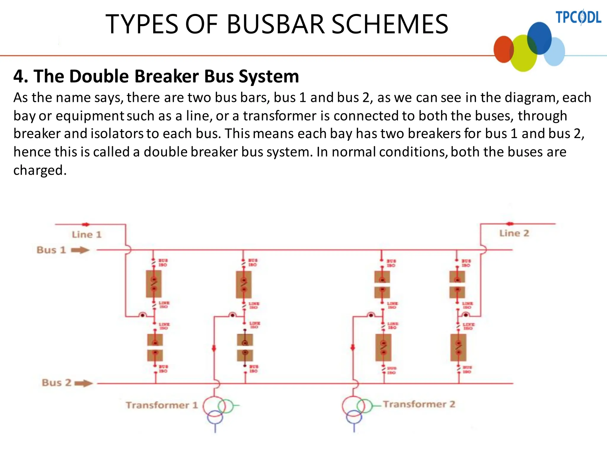
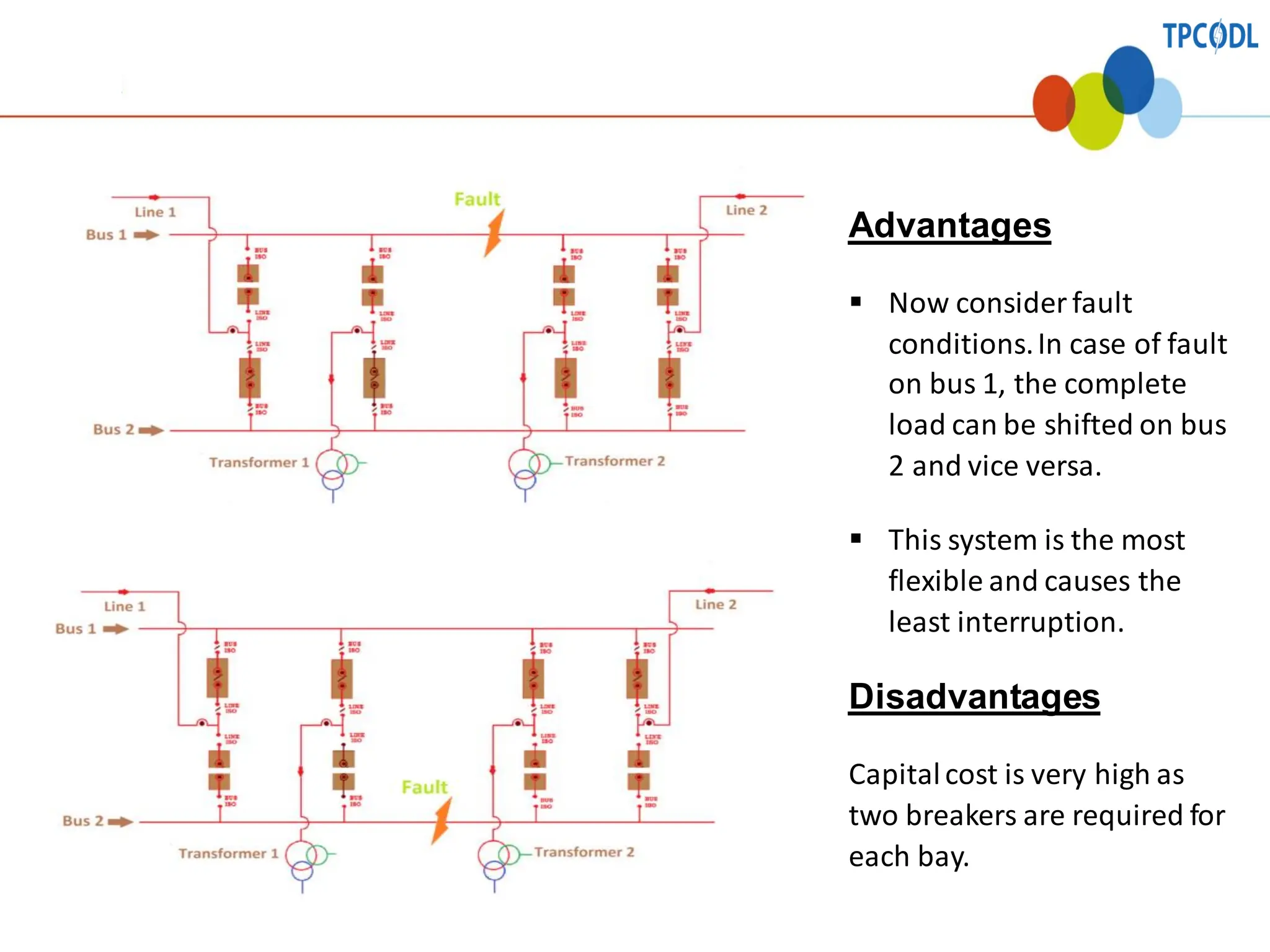
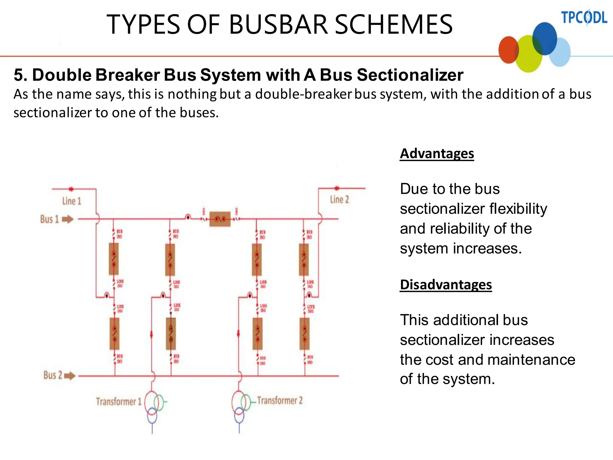
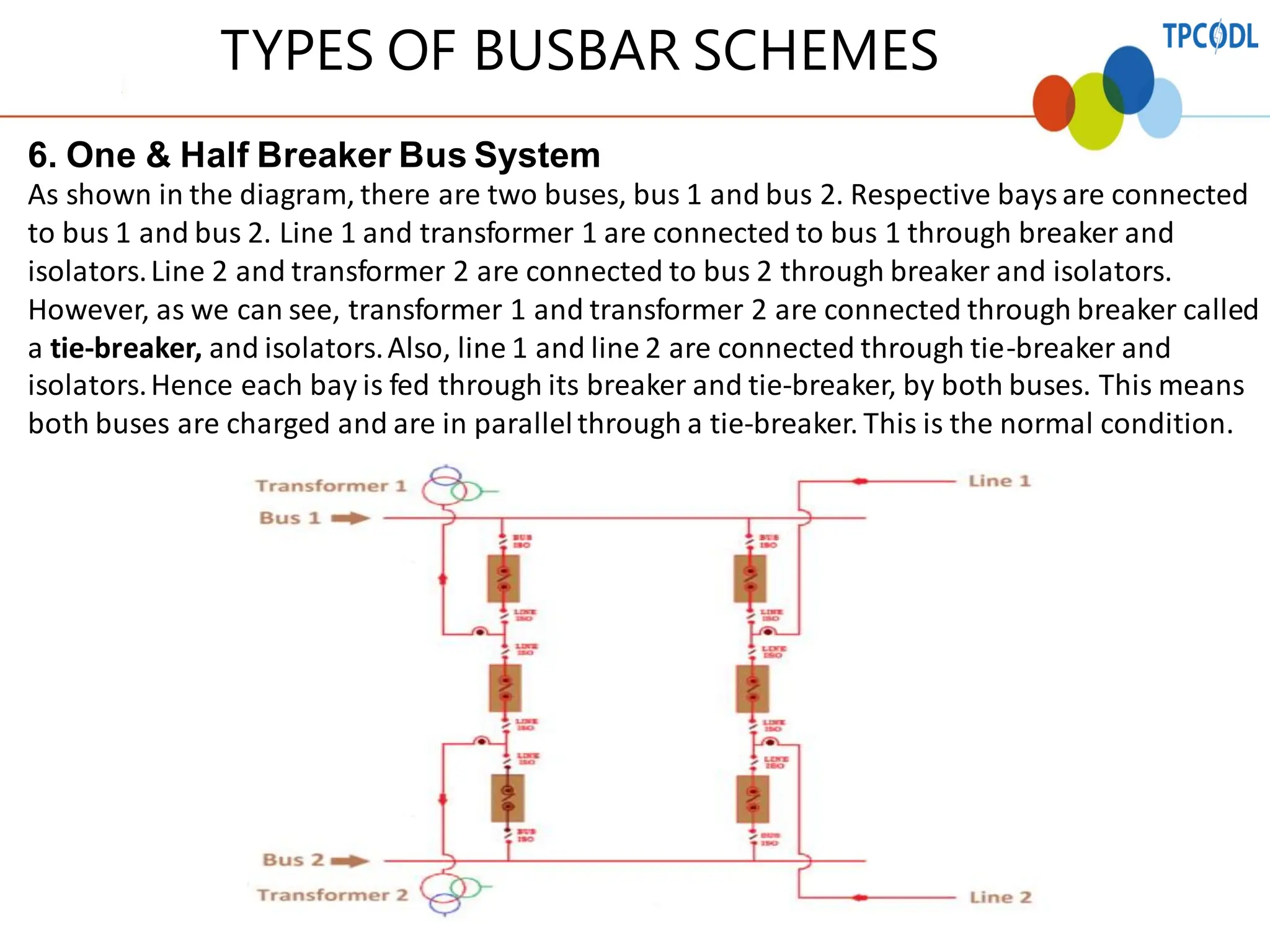
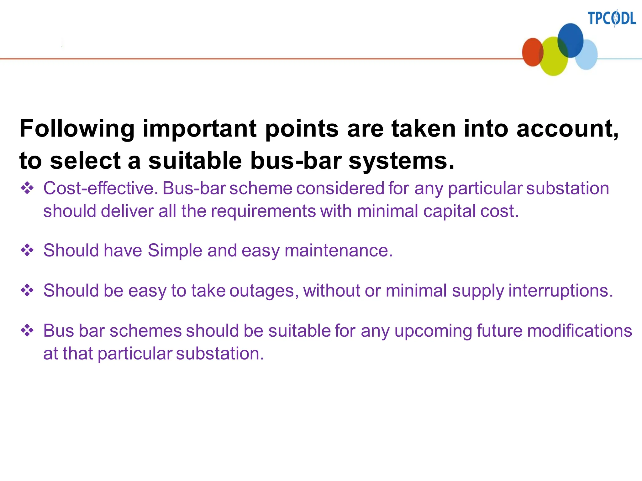
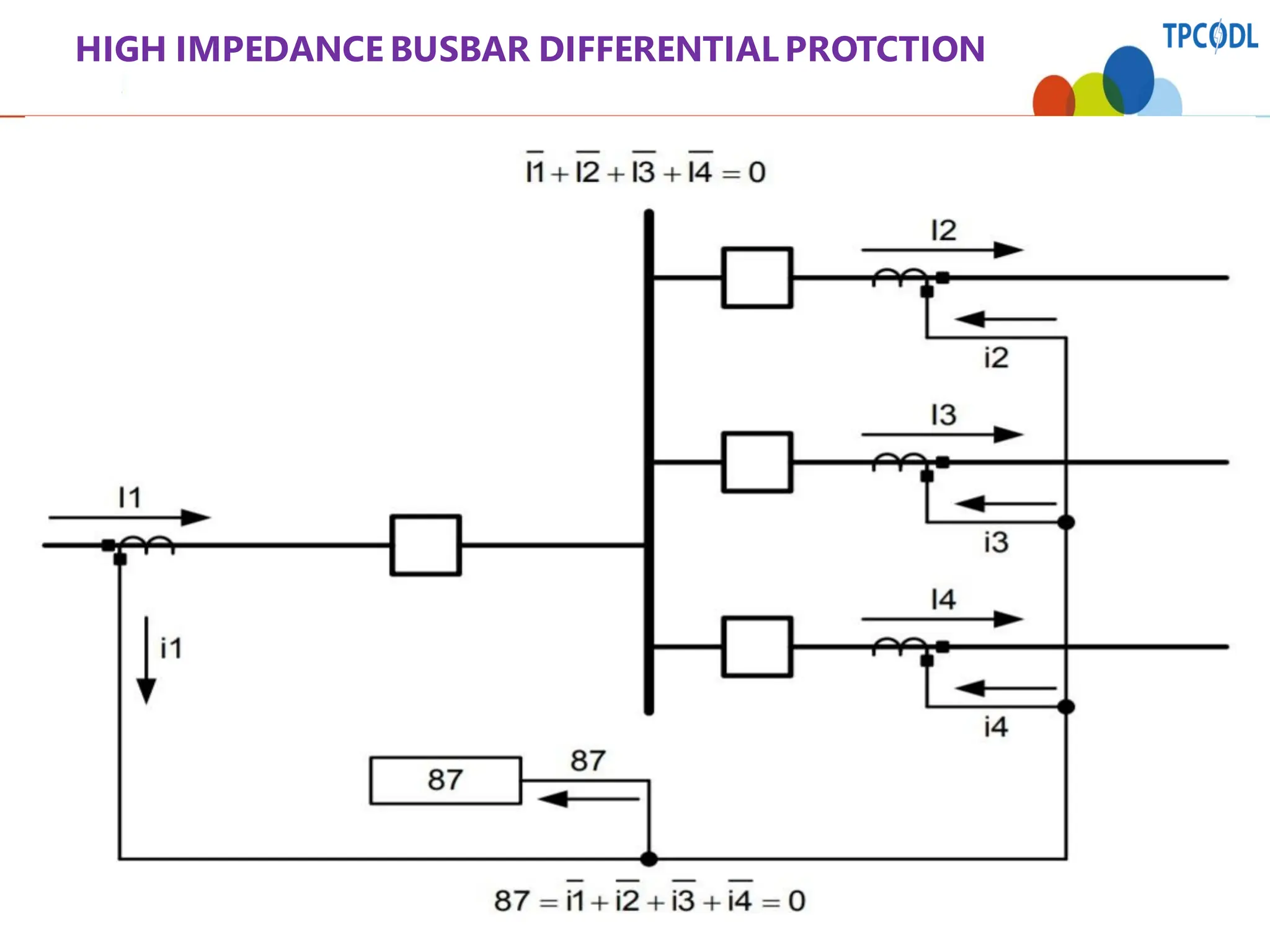
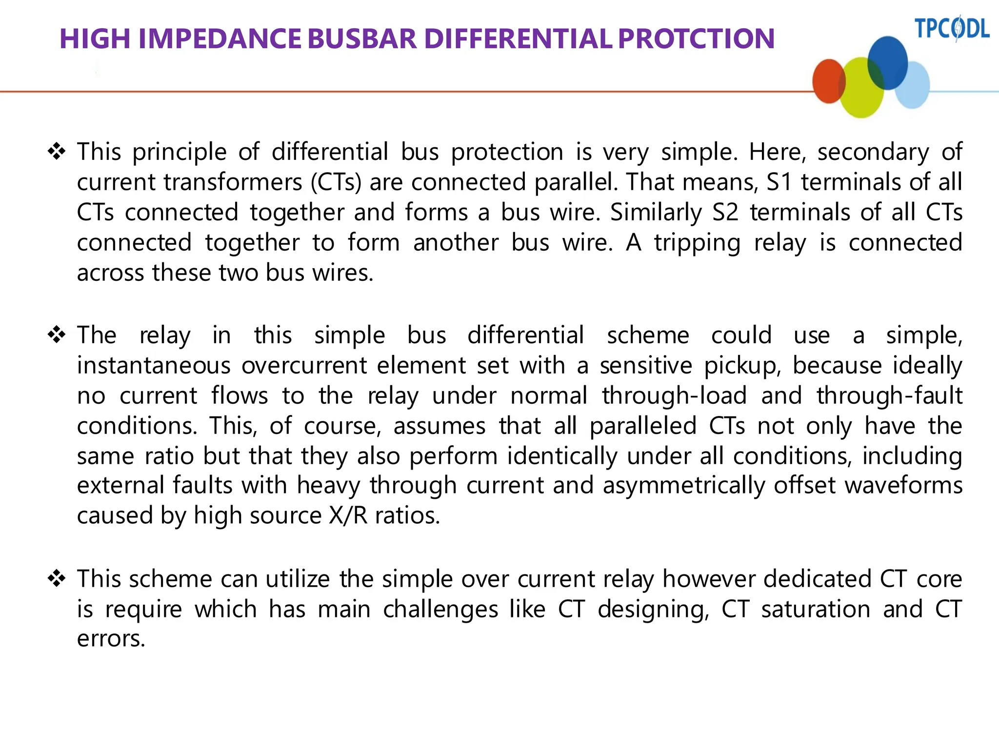
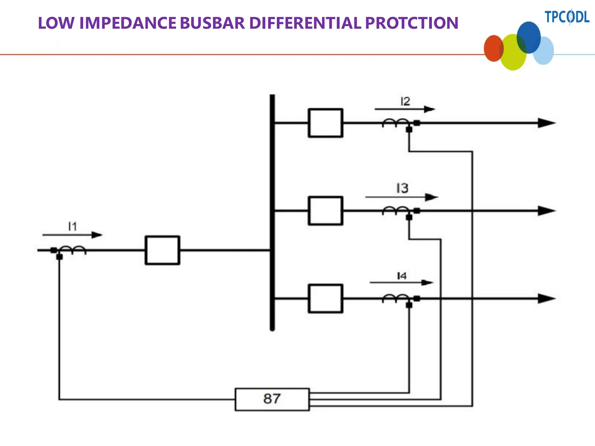
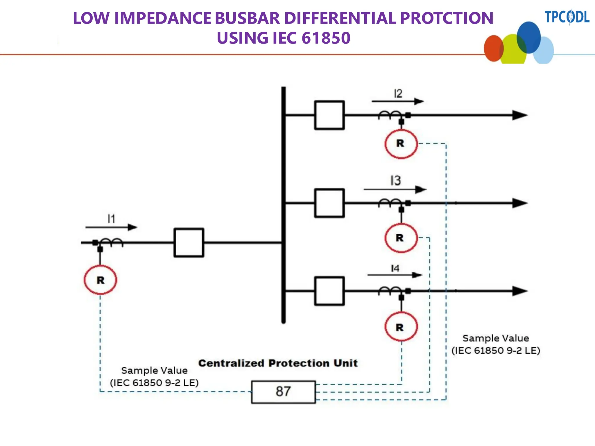
1
Busbar in Sub-station
&
It’s Protection
By Susanta Kumar Swain
Deputy Manager, P&T,JSS tower
2
• An abnormality or failure of primary
equipment
Power system
faults
• Faults other than a power system fault ( e.g:
secondary equipment failure , human errors)
Non-system
faults
• Sequence of power system faults that we
treat as one incident.
Power system
disturbances
Types of Faults
3
•Why Protection is needed ?
•Principles and elements of the protection
system ?
•Basic Protection schemes ?
Power System Protection
Protection – Fault Clearance System
Trip
coil
Protection
Equipment
TE
Protection System
Circuit Breaker
Circuit
Breaker
Mechanism
CT
VT
DC - System
5
Need for Protection
The Power system must maintain Un interrupted
supply Voltage and frequency must stay within
certain limits.
▪ Protect the Human Life
▪ Improve system stability
▪ Minimize damage to equipment.
6
It’s the study about protection of all equipments in power supply system
and the system may be a Generating plant, Transmission line,
distribution system and other electrical equipments. The Protection
system should be :-
1)Dependable ( Operate when required)
2)Secure (Not operate unnecessarily)
3)Selective (Only minimum nos of devices should operate)
4) Speed (To operate as quick as possible)
What is Protection System
7
What is a Substation?
❑ A substation is a part of an electrical generation, transmission
and distribution system. Substationstransform voltage from high
to low, or the reverse, or perform any of several other important
functions. Between the generating station and consumer, electric
power may flow through several substationsat different voltage
levels.
❑ A substationmay include transformers to change voltage levels
between high transmission voltages and lower distribution
voltages, or at the interconnectionof two different transmission
voltages.
❑ Substationsmay be owned and operated by an electrical utility, or
may be owned by a large industrial or commercialcustomer.
Generally substationsare unattended, relying on SCADA for
remote supervision and control.
8
TYPES OF SUB-STATION
Substations may be described by their voltage class, their applications within the
power system etc.
❖ Transmission sub-station:- A transmission substation connects two or more
transmission lines. The simplest case is where all transmission lines havethe same
voltage. In such cases, substationcontainshigh-voltageswitches that allow lines to be
connected or isolatedfor fault clearance or maintenance.A transmission stationmay
have transformers to convert between two transmission voltages, power factor
correction devices, devices such as capacitors,reactors or static VAR compensators and
equipment such as phase shifting transformers to controlpower flow between two
adjacentpower systems.
❖ Distribution sub-station :- A distribution substation transfers power from the
transmission system to the distributionsystem of an area.[3] It is uneconomicalto
directly connect electricity consumers to the main transmission network, unless they use
large amountsof power, so the distributionstationreduces voltageto a level suitablefor
local distribution.
❖ Switching sub-station:- A switching station is a substationwithout transformers and
operatingonly at a single voltage level. Switching stationsare sometimes used as
collectorand distributionstations. Sometimes they are used for switching the current to
back-up lines or for parallelizingcircuitsin case of failure.
9
SINGLE LINE DIAGRAM OF A SUB-STATION
10
What is a bus bar?
• In Simple words, a bus-bar is a common connection point or
a node for multiple incoming and outgoing circuits such as
power lines or feeders. As we know it is impractical to
connect multiple conductors at one point.
• Hence we use bus bars, where these connections can be
done spaciously and conveniently.
BUSBAR
11
TYPES OF BUSBAR SCHEMES
1. Single Bus System
This is the most basic and simple Bus Bar system. As we can see in the diagram. In
this type, all incoming and outgoing bays such as lines, transformers, and feeders are
directly connected to a single bus.
12
Advantages:-
• Due to its simple design,it is easy
and convenient to operate.
• It is very economical,because of its
least capital cost among all bus Bar
systems.
Disadvantages:-
▪ In this type, maintenance activity of
any bay or equipmentsuch as a
transformeris not possiblewithout
service interruption of the particular
bay or equipment.
▪ In case of fault on bus or bus
outage for maintenance, all the
bays connected to the bus get
interrupted.
13
TYPES OF BUSBAR SCHEMES
2. Single Bus with Bus Sectionalizer System
This is a single bus system, with additional circuit breaker and isolators, making two
different sections of bus, hence called a single bus system with bus sectionalizer.
14
Advantages:-
▪ Since there are two sections, separated
by a circuit breaker, the fault on one
section does not interrupt the other
section of the bus. Circuit breaker
isolates faulty section from the healthy
one.
▪ Maintenance of the bus section can be
done individually, without affecting other
section. Hence power supply continuity
is maintained.
Disadvantages
▪ The cost of circuit breaker and isolators
is added to the capital cost.
15
TYPES OF BUSBAR SCHEMES
3. Main & Transfer Bus System
As shown in the diagram. There are two buses, one main bus and the other transfer bus also
called an auxiliary bus. Each bay or equipment such as line, and transformer are connected to
both the buses, to main bus through circuit breaker and isolators,and to transfer bus through
auxiliaryisolator only. These two buses are connected by circuit breaker and isolators,called
bus coupler, and this bay is called transferbus coupler TBC bay. In normal conditions,the load
of all bays is on the main bus, and the transfer bus is in standbymode, which means auxiliary
isolatorsare open. Also, TBC bay circuit breaker and isolators are open. So this is a normal
condition.
16
Advantages
▪ Circuit breaker maintenance
of any bay can be done
without interrupting the
power supply.
▪ This arrangement provides
more flexibility
Disadvantages
▪ The only disadvantage is that
it adds up the cost of the
auxiliary bus, TBC breaker,
and isolators.
17
TYPES OF BUSBAR SCHEMES
4. The Double Breaker Bus System
As the name says, there are two bus bars, bus 1 and bus 2, as we can see in the diagram, each
bay or equipmentsuch as a line, or a transformer is connected to both the buses, through
breaker and isolators to each bus. This means each bay has two breakers for bus 1 and bus 2,
hence this is called a double breaker bus system. In normal conditions,both the buses are
charged.
18
Advantages
▪ Now consider fault
conditions.In case of fault
on bus 1, the complete
load can be shifted on bus
2 and vice versa.
▪ This system is the most
flexible and causes the
least interruption.
Disadvantages
Capitalcost is very high as
two breakers are required for
each bay.
19
TYPES OF BUSBAR SCHEMES
5. Double Breaker Bus System with A Bus Sectionalizer
As the name says, this is nothing but a double-breakerbus system, with the additionof a bus
sectionalizer to one of the buses.
Advantages
Due to the bus
sectionalizer flexibility
and reliability of the
system increases.
Disadvantages
This additional bus
sectionalizer increases
the cost and maintenance
of the system.
20
TYPES OF BUSBAR SCHEMES
6. One & Half Breaker Bus System
As shown in the diagram, there are two buses, bus 1 and bus 2. Respective bays are connected
to bus 1 and bus 2. Line 1 and transformer 1 are connected to bus 1 through breaker and
isolators.Line 2 and transformer 2 are connected to bus 2 through breaker and isolators.
However, as we can see, transformer 1 and transformer 2 are connected through breaker called
a tie-breaker, and isolators.Also, line 1 and line 2 are connected through tie-breaker and
isolators.Hence each bay is fed through its breaker and tie-breaker, by both buses. This means
both buses are charged and are in parallelthrough a tie-breaker. This is the normal condition.
21
Now consider fault
conditions, in case of
fault on bus 1, the
complete load gets
shifted on bus 2.
And in case of fault
on bus 2, the
complete load gets
shifted on bus 1,
without any
interruption.
22
In this system, two bays have a common tie-breaker, which means two bays have a
total of three breakers instead of four. Hence called a one and half breaker system.
Advantages
As seen, there is no
interruption at all in
case of fault or failure
of any one of the
buses.
Disadvantages
Capital cost is high
since additional tie-
breaker and
associated isolators
are required.
23
TYPES OF BUSBAR SCHEMES
7. Double Bus System with Bypass Isolators
This is nothing but a main and transfer bus system with the additionof bypass isolators to each
bay. In normal conditions,we can see the load is on the main bus, with bypass isolators open.
24
Now transfer bus can be used as the main bus, and the main bus as the transfer bus by
closing bypass isolators and opening respective bus isolators. Please note that shut
down is required to shift the complete load on another bus, to use as the main bus.
TBC operation is the same as we discussed in the main and transfer bus system.
25
Advantages
Generally, main bus equipment is in
constant service, whereas transfer
bus equipment is taken in service
only during maintenance of main bus
equipment. But due to this
arrangement, the role of the main and
transfer bus can be interchanged, and
we can use the equipment
alternatively. This increases the
lifespan of all the equipment
altogether.
Disadvantages
The cost of the bypass isolator is
added to the capital cost.
26
TYPES OF BUSBAR SCHEMES
8. Ring Main Bus System
This is an improvisedversion of sectionalized bus bar system. As shown in the diagram,
sectionalized bus bar ends are connected with another bus bar, with bus couplers to form a
closed loop. Hence called as ring main bus system. And on the loop different incoming and
outgoing circuits are connected, such as line 1 with its breaker and isolators, similarlyline 2,
transformer 1, transformer 2, feeder 1 & feeder 2 with their respective breakers and isolators.
27
Advantages
In this system double feed is provided to each bay. In case of failure of any one of the
feeds, other feeds continue to supply the feeder, hence no interruption. So
maintenance of any breaker can be done without any interruption.
Also in case of fault on a bus, only associated breakers get tripped, hence fault does
not interrupt complete load. Thus fault is localized.
28
Disadvantages
If any one of the breakers is under outage, which makes it open. During this time, if
any other breaker trips, it may affect one or more than one bays, depending upon
the location of a tripped breaker.
Also, the load may imbalance in case any one of the breakers is opened.
29
TYPES OF BUSBAR SCHEMES
9. Mesh Bus System
As shown in the diagram, in this type breakers are connected with the mesh formation of the
bus. As we can see, bays are connected to node points of mesh. Here line 1, line 2, transformer
1, transformer 2, feeder 1, 2, 3 & 4 are connected to node points. That means eight bays are
controlledby four circuit breakers. This system is used in the substationwith a large number of
circuits.
30
Advantages
In case of fault on a bus, both side circuit breakers open. And the fault is localized.
Hence complete load is not affected.
Disadvantages
This type of system provides a limited switching facility since two circuit breakers jointlycontrol
two circuits at node points.
31
Following important points are taken into account,
to select a suitable bus-bar systems.
❖ Cost-effective. Bus-bar scheme considered for any particular substation
should deliver all the requirements with minimal capital cost.
❖ Should have Simple and easy maintenance.
❖ Should be easy to take outages, without or minimal supply interruptions.
❖ Bus bar schemes should be suitable for any upcoming future modifications
at that particular substation.
32
WHAT IS THE NEED FOR BUSBAR DIFFERENTIAL PROTECTION ?
Mostly only conventional over current relays are used for bus bar protection
in MV switchboards. The main disadvantage of this approach is time setting
for bus protection relays. It is desired that the bus bar faults should be cleared
soonest possible to avoid damage to bus bar of MV switchboards and it
should not operate during the external faults. However, only time and current
based discrimination between the bus faults and external faults is difficult to
achieve. To overcome the above mentioned difficulties, current based
differential bus protection scheme with an operating time typically less than
0.1 sec., is commonly applied to MV bus systems.
The scheme of bus protection, involves, Kirchoff’s current law, which states
that, total current entering an electrical node is exactly equal to total current
leaving the node. Hence, total current entering into a bus section is equal to
total current leaving the bus section. Two drastically different types of bus bar
differential relay scheme, one with a single set of very high-impedance inputs
and another with multiple sets of low-impedance inputs, are available for bus
differential protection.
BUSBAR DIFFERENTIAL PROTECTION
33
HIGH IMPEDANCE BUSBAR DIFFERENTIAL PROTCTION
34
HIGH IMPEDANCE BUSBAR DIFFERENTIAL PROTCTION
❖ This principle of differential bus protection is very simple. Here, secondary of
current transformers (CTs) are connected parallel. That means, S1 terminals of all
CTs connected together and forms a bus wire. Similarly S2 terminals of all CTs
connected together to form another bus wire. A tripping relay is connected
across these two bus wires.
❖ The relay in this simple bus differential scheme could use a simple,
instantaneous overcurrent element set with a sensitive pickup, because ideally
no current flows to the relay under normal through-load and through-fault
conditions. This, of course, assumes that all paralleled CTs not only have the
same ratio but that they also perform identically under all conditions, including
external faults with heavy through current and asymmetrically offset waveforms
caused by high source X/R ratios.
❖ This scheme can utilize the simple over current relay however dedicated CT core
is require which has main challenges like CT designing, CT saturation and CT
errors.
35
LOW IMPEDANCE BUSBAR DIFFERENTIAL PROTCTION
36
LOW IMPEDANCE BUSBAR DIFFERENTIAL PROTCTION
➢ Low-impedance bus differential relays are so named because the differential
relay current inputs have a low impedance to the flow of CT secondary
current. This means that the low-impedance bus differential relays can share
the CTs with other relays, meters, transducers, etc.
➢ The low impedance bus differential scheme typically has one set of current
inputs for each phase from every set of CTs in the scheme. Having individual
current inputs also allows the circuits comprising the differential zone to have
different CT ratios, an important attribute where the CTs are shared with other
protection and monitoring functions.
➢ The relay compensates for the difference in secondary current magnitudes
from different CT ratios by using tap settings on each input to normalize the
currents to a common base. Biased differential characteristic is used for this
scheme which gives better selectivity for through faults, CT errors and CT
saturation issues. This scheme will require dedicated bus differential
protection relay and generally this scheme is costly compare to earlier one.
37
LOW IMPEDANCE BUSBAR DIFFERENTIAL PROTCTION
USING IEC 61850
38
✓ The new approach to these challenges is to utilize latest IEC 61850 protocol.
IEC 61850 9-2LE allows utilization of sample values for low impedance bus
differential scheme as shown in the figure.
✓ The prerequisite is feeder protection relays should support sample values as
per IEC 61850 9-2LE standard or usage of dedicated merging units per feeder
for the scheme. Also, centralized protection unit is required which can host
low impedance based bus differential protection function.
✓ ABB's SSC600 - Smart Substation control and protection unit is the smart
choice for such application which can provide centralized protection for bus
differential scheme up to 20 feeders with single or double bus zone and
overall check zone protection. The major advantage for such scheme is easy
and faster deployment compare to any other approach.
LOW IMPEDANCE BUSBAR DIFFERENTIAL PROTCTION
USING IEC 61850
39
Let's quickly compare the various scheme in below table.
The end user needs to evaluate the advantages and disadvantages of each scheme based on the
intended application and installation. Of course, low impedance bus differential scheme will provide lot
of other benefits of centralized protection and control system.
40
• Provides back-up protection for the both the relays (main-1 & main-
2) and breakers at remote substation.
REMOTE BACK-UP
• Provides back-up protection for faults not cleared by local
protection.
LOCAL BACK-UP
BASICS OF LBB/BFR PROTECTION
LBB/BFR FLOW CHART
MAIN
PROTECTION
OPERATED
YES TRIP
MAIN
BREAKER
YES INITIATE
BFR
WAIT FOR
FAULT
CLEARENCE
AND
FAULT
CLEARED
YES
RESET
BREAKER
FAILURE
SCHEME
TRIP
BACK-UP
BREAKERS
NO
42

14 Busbars in Sub-station and It's Protection.pdf

  • 1.
    1 Busbar in Sub-station & It’sProtection By Susanta Kumar Swain Deputy Manager, P&T,JSS tower
  • 2.
    2 • An abnormalityor failure of primary equipment Power system faults • Faults other than a power system fault ( e.g: secondary equipment failure , human errors) Non-system faults • Sequence of power system faults that we treat as one incident. Power system disturbances Types of Faults
  • 3.
    3 •Why Protection isneeded ? •Principles and elements of the protection system ? •Basic Protection schemes ? Power System Protection
  • 4.
    Protection – FaultClearance System Trip coil Protection Equipment TE Protection System Circuit Breaker Circuit Breaker Mechanism CT VT DC - System
  • 5.
    5 Need for Protection ThePower system must maintain Un interrupted supply Voltage and frequency must stay within certain limits. ▪ Protect the Human Life ▪ Improve system stability ▪ Minimize damage to equipment.
  • 6.
    6 It’s the studyabout protection of all equipments in power supply system and the system may be a Generating plant, Transmission line, distribution system and other electrical equipments. The Protection system should be :- 1)Dependable ( Operate when required) 2)Secure (Not operate unnecessarily) 3)Selective (Only minimum nos of devices should operate) 4) Speed (To operate as quick as possible) What is Protection System
  • 7.
    7 What is aSubstation? ❑ A substation is a part of an electrical generation, transmission and distribution system. Substationstransform voltage from high to low, or the reverse, or perform any of several other important functions. Between the generating station and consumer, electric power may flow through several substationsat different voltage levels. ❑ A substationmay include transformers to change voltage levels between high transmission voltages and lower distribution voltages, or at the interconnectionof two different transmission voltages. ❑ Substationsmay be owned and operated by an electrical utility, or may be owned by a large industrial or commercialcustomer. Generally substationsare unattended, relying on SCADA for remote supervision and control.
  • 8.
    8 TYPES OF SUB-STATION Substationsmay be described by their voltage class, their applications within the power system etc. ❖ Transmission sub-station:- A transmission substation connects two or more transmission lines. The simplest case is where all transmission lines havethe same voltage. In such cases, substationcontainshigh-voltageswitches that allow lines to be connected or isolatedfor fault clearance or maintenance.A transmission stationmay have transformers to convert between two transmission voltages, power factor correction devices, devices such as capacitors,reactors or static VAR compensators and equipment such as phase shifting transformers to controlpower flow between two adjacentpower systems. ❖ Distribution sub-station :- A distribution substation transfers power from the transmission system to the distributionsystem of an area.[3] It is uneconomicalto directly connect electricity consumers to the main transmission network, unless they use large amountsof power, so the distributionstationreduces voltageto a level suitablefor local distribution. ❖ Switching sub-station:- A switching station is a substationwithout transformers and operatingonly at a single voltage level. Switching stationsare sometimes used as collectorand distributionstations. Sometimes they are used for switching the current to back-up lines or for parallelizingcircuitsin case of failure.
  • 9.
    9 SINGLE LINE DIAGRAMOF A SUB-STATION
  • 10.
    10 What is abus bar? • In Simple words, a bus-bar is a common connection point or a node for multiple incoming and outgoing circuits such as power lines or feeders. As we know it is impractical to connect multiple conductors at one point. • Hence we use bus bars, where these connections can be done spaciously and conveniently. BUSBAR
  • 11.
    11 TYPES OF BUSBARSCHEMES 1. Single Bus System This is the most basic and simple Bus Bar system. As we can see in the diagram. In this type, all incoming and outgoing bays such as lines, transformers, and feeders are directly connected to a single bus.
  • 12.
    12 Advantages:- • Due toits simple design,it is easy and convenient to operate. • It is very economical,because of its least capital cost among all bus Bar systems. Disadvantages:- ▪ In this type, maintenance activity of any bay or equipmentsuch as a transformeris not possiblewithout service interruption of the particular bay or equipment. ▪ In case of fault on bus or bus outage for maintenance, all the bays connected to the bus get interrupted.
  • 13.
    13 TYPES OF BUSBARSCHEMES 2. Single Bus with Bus Sectionalizer System This is a single bus system, with additional circuit breaker and isolators, making two different sections of bus, hence called a single bus system with bus sectionalizer.
  • 14.
    14 Advantages:- ▪ Since thereare two sections, separated by a circuit breaker, the fault on one section does not interrupt the other section of the bus. Circuit breaker isolates faulty section from the healthy one. ▪ Maintenance of the bus section can be done individually, without affecting other section. Hence power supply continuity is maintained. Disadvantages ▪ The cost of circuit breaker and isolators is added to the capital cost.
  • 15.
    15 TYPES OF BUSBARSCHEMES 3. Main & Transfer Bus System As shown in the diagram. There are two buses, one main bus and the other transfer bus also called an auxiliary bus. Each bay or equipment such as line, and transformer are connected to both the buses, to main bus through circuit breaker and isolators,and to transfer bus through auxiliaryisolator only. These two buses are connected by circuit breaker and isolators,called bus coupler, and this bay is called transferbus coupler TBC bay. In normal conditions,the load of all bays is on the main bus, and the transfer bus is in standbymode, which means auxiliary isolatorsare open. Also, TBC bay circuit breaker and isolators are open. So this is a normal condition.
  • 16.
    16 Advantages ▪ Circuit breakermaintenance of any bay can be done without interrupting the power supply. ▪ This arrangement provides more flexibility Disadvantages ▪ The only disadvantage is that it adds up the cost of the auxiliary bus, TBC breaker, and isolators.
  • 17.
    17 TYPES OF BUSBARSCHEMES 4. The Double Breaker Bus System As the name says, there are two bus bars, bus 1 and bus 2, as we can see in the diagram, each bay or equipmentsuch as a line, or a transformer is connected to both the buses, through breaker and isolators to each bus. This means each bay has two breakers for bus 1 and bus 2, hence this is called a double breaker bus system. In normal conditions,both the buses are charged.
  • 18.
    18 Advantages ▪ Now considerfault conditions.In case of fault on bus 1, the complete load can be shifted on bus 2 and vice versa. ▪ This system is the most flexible and causes the least interruption. Disadvantages Capitalcost is very high as two breakers are required for each bay.
  • 19.
    19 TYPES OF BUSBARSCHEMES 5. Double Breaker Bus System with A Bus Sectionalizer As the name says, this is nothing but a double-breakerbus system, with the additionof a bus sectionalizer to one of the buses. Advantages Due to the bus sectionalizer flexibility and reliability of the system increases. Disadvantages This additional bus sectionalizer increases the cost and maintenance of the system.
  • 20.
    20 TYPES OF BUSBARSCHEMES 6. One & Half Breaker Bus System As shown in the diagram, there are two buses, bus 1 and bus 2. Respective bays are connected to bus 1 and bus 2. Line 1 and transformer 1 are connected to bus 1 through breaker and isolators.Line 2 and transformer 2 are connected to bus 2 through breaker and isolators. However, as we can see, transformer 1 and transformer 2 are connected through breaker called a tie-breaker, and isolators.Also, line 1 and line 2 are connected through tie-breaker and isolators.Hence each bay is fed through its breaker and tie-breaker, by both buses. This means both buses are charged and are in parallelthrough a tie-breaker. This is the normal condition.
  • 21.
    21 Now consider fault conditions,in case of fault on bus 1, the complete load gets shifted on bus 2. And in case of fault on bus 2, the complete load gets shifted on bus 1, without any interruption.
  • 22.
    22 In this system,two bays have a common tie-breaker, which means two bays have a total of three breakers instead of four. Hence called a one and half breaker system. Advantages As seen, there is no interruption at all in case of fault or failure of any one of the buses. Disadvantages Capital cost is high since additional tie- breaker and associated isolators are required.
  • 23.
    23 TYPES OF BUSBARSCHEMES 7. Double Bus System with Bypass Isolators This is nothing but a main and transfer bus system with the additionof bypass isolators to each bay. In normal conditions,we can see the load is on the main bus, with bypass isolators open.
  • 24.
    24 Now transfer buscan be used as the main bus, and the main bus as the transfer bus by closing bypass isolators and opening respective bus isolators. Please note that shut down is required to shift the complete load on another bus, to use as the main bus. TBC operation is the same as we discussed in the main and transfer bus system.
  • 25.
    25 Advantages Generally, main busequipment is in constant service, whereas transfer bus equipment is taken in service only during maintenance of main bus equipment. But due to this arrangement, the role of the main and transfer bus can be interchanged, and we can use the equipment alternatively. This increases the lifespan of all the equipment altogether. Disadvantages The cost of the bypass isolator is added to the capital cost.
  • 26.
    26 TYPES OF BUSBARSCHEMES 8. Ring Main Bus System This is an improvisedversion of sectionalized bus bar system. As shown in the diagram, sectionalized bus bar ends are connected with another bus bar, with bus couplers to form a closed loop. Hence called as ring main bus system. And on the loop different incoming and outgoing circuits are connected, such as line 1 with its breaker and isolators, similarlyline 2, transformer 1, transformer 2, feeder 1 & feeder 2 with their respective breakers and isolators.
  • 27.
    27 Advantages In this systemdouble feed is provided to each bay. In case of failure of any one of the feeds, other feeds continue to supply the feeder, hence no interruption. So maintenance of any breaker can be done without any interruption. Also in case of fault on a bus, only associated breakers get tripped, hence fault does not interrupt complete load. Thus fault is localized.
  • 28.
    28 Disadvantages If any oneof the breakers is under outage, which makes it open. During this time, if any other breaker trips, it may affect one or more than one bays, depending upon the location of a tripped breaker. Also, the load may imbalance in case any one of the breakers is opened.
  • 29.
    29 TYPES OF BUSBARSCHEMES 9. Mesh Bus System As shown in the diagram, in this type breakers are connected with the mesh formation of the bus. As we can see, bays are connected to node points of mesh. Here line 1, line 2, transformer 1, transformer 2, feeder 1, 2, 3 & 4 are connected to node points. That means eight bays are controlledby four circuit breakers. This system is used in the substationwith a large number of circuits.
  • 30.
    30 Advantages In case offault on a bus, both side circuit breakers open. And the fault is localized. Hence complete load is not affected. Disadvantages This type of system provides a limited switching facility since two circuit breakers jointlycontrol two circuits at node points.
  • 31.
    31 Following important pointsare taken into account, to select a suitable bus-bar systems. ❖ Cost-effective. Bus-bar scheme considered for any particular substation should deliver all the requirements with minimal capital cost. ❖ Should have Simple and easy maintenance. ❖ Should be easy to take outages, without or minimal supply interruptions. ❖ Bus bar schemes should be suitable for any upcoming future modifications at that particular substation.
  • 32.
    32 WHAT IS THENEED FOR BUSBAR DIFFERENTIAL PROTECTION ? Mostly only conventional over current relays are used for bus bar protection in MV switchboards. The main disadvantage of this approach is time setting for bus protection relays. It is desired that the bus bar faults should be cleared soonest possible to avoid damage to bus bar of MV switchboards and it should not operate during the external faults. However, only time and current based discrimination between the bus faults and external faults is difficult to achieve. To overcome the above mentioned difficulties, current based differential bus protection scheme with an operating time typically less than 0.1 sec., is commonly applied to MV bus systems. The scheme of bus protection, involves, Kirchoff’s current law, which states that, total current entering an electrical node is exactly equal to total current leaving the node. Hence, total current entering into a bus section is equal to total current leaving the bus section. Two drastically different types of bus bar differential relay scheme, one with a single set of very high-impedance inputs and another with multiple sets of low-impedance inputs, are available for bus differential protection. BUSBAR DIFFERENTIAL PROTECTION
  • 33.
    33 HIGH IMPEDANCE BUSBARDIFFERENTIAL PROTCTION
  • 34.
    34 HIGH IMPEDANCE BUSBARDIFFERENTIAL PROTCTION ❖ This principle of differential bus protection is very simple. Here, secondary of current transformers (CTs) are connected parallel. That means, S1 terminals of all CTs connected together and forms a bus wire. Similarly S2 terminals of all CTs connected together to form another bus wire. A tripping relay is connected across these two bus wires. ❖ The relay in this simple bus differential scheme could use a simple, instantaneous overcurrent element set with a sensitive pickup, because ideally no current flows to the relay under normal through-load and through-fault conditions. This, of course, assumes that all paralleled CTs not only have the same ratio but that they also perform identically under all conditions, including external faults with heavy through current and asymmetrically offset waveforms caused by high source X/R ratios. ❖ This scheme can utilize the simple over current relay however dedicated CT core is require which has main challenges like CT designing, CT saturation and CT errors.
  • 35.
    35 LOW IMPEDANCE BUSBARDIFFERENTIAL PROTCTION
  • 36.
    36 LOW IMPEDANCE BUSBARDIFFERENTIAL PROTCTION ➢ Low-impedance bus differential relays are so named because the differential relay current inputs have a low impedance to the flow of CT secondary current. This means that the low-impedance bus differential relays can share the CTs with other relays, meters, transducers, etc. ➢ The low impedance bus differential scheme typically has one set of current inputs for each phase from every set of CTs in the scheme. Having individual current inputs also allows the circuits comprising the differential zone to have different CT ratios, an important attribute where the CTs are shared with other protection and monitoring functions. ➢ The relay compensates for the difference in secondary current magnitudes from different CT ratios by using tap settings on each input to normalize the currents to a common base. Biased differential characteristic is used for this scheme which gives better selectivity for through faults, CT errors and CT saturation issues. This scheme will require dedicated bus differential protection relay and generally this scheme is costly compare to earlier one.
  • 37.
    37 LOW IMPEDANCE BUSBARDIFFERENTIAL PROTCTION USING IEC 61850
  • 38.
    38 ✓ The newapproach to these challenges is to utilize latest IEC 61850 protocol. IEC 61850 9-2LE allows utilization of sample values for low impedance bus differential scheme as shown in the figure. ✓ The prerequisite is feeder protection relays should support sample values as per IEC 61850 9-2LE standard or usage of dedicated merging units per feeder for the scheme. Also, centralized protection unit is required which can host low impedance based bus differential protection function. ✓ ABB's SSC600 - Smart Substation control and protection unit is the smart choice for such application which can provide centralized protection for bus differential scheme up to 20 feeders with single or double bus zone and overall check zone protection. The major advantage for such scheme is easy and faster deployment compare to any other approach. LOW IMPEDANCE BUSBAR DIFFERENTIAL PROTCTION USING IEC 61850
  • 39.
    39 Let's quickly comparethe various scheme in below table. The end user needs to evaluate the advantages and disadvantages of each scheme based on the intended application and installation. Of course, low impedance bus differential scheme will provide lot of other benefits of centralized protection and control system.
  • 40.
    40 • Provides back-upprotection for the both the relays (main-1 & main- 2) and breakers at remote substation. REMOTE BACK-UP • Provides back-up protection for faults not cleared by local protection. LOCAL BACK-UP BASICS OF LBB/BFR PROTECTION
  • 41.
    LBB/BFR FLOW CHART MAIN PROTECTION OPERATED YESTRIP MAIN BREAKER YES INITIATE BFR WAIT FOR FAULT CLEARENCE AND FAULT CLEARED YES RESET BREAKER FAILURE SCHEME TRIP BACK-UP BREAKERS NO
  • 42.