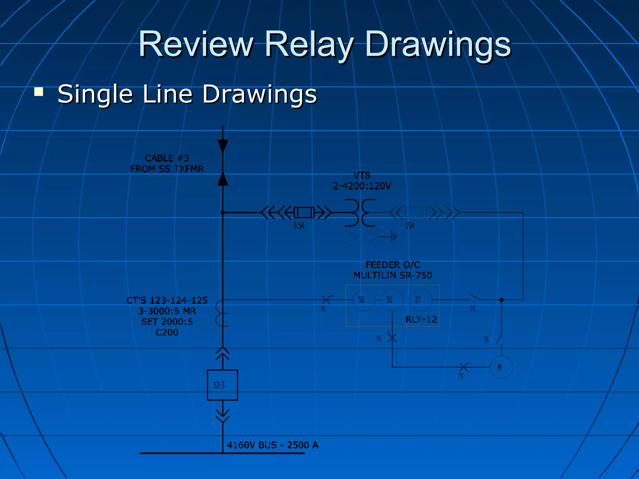
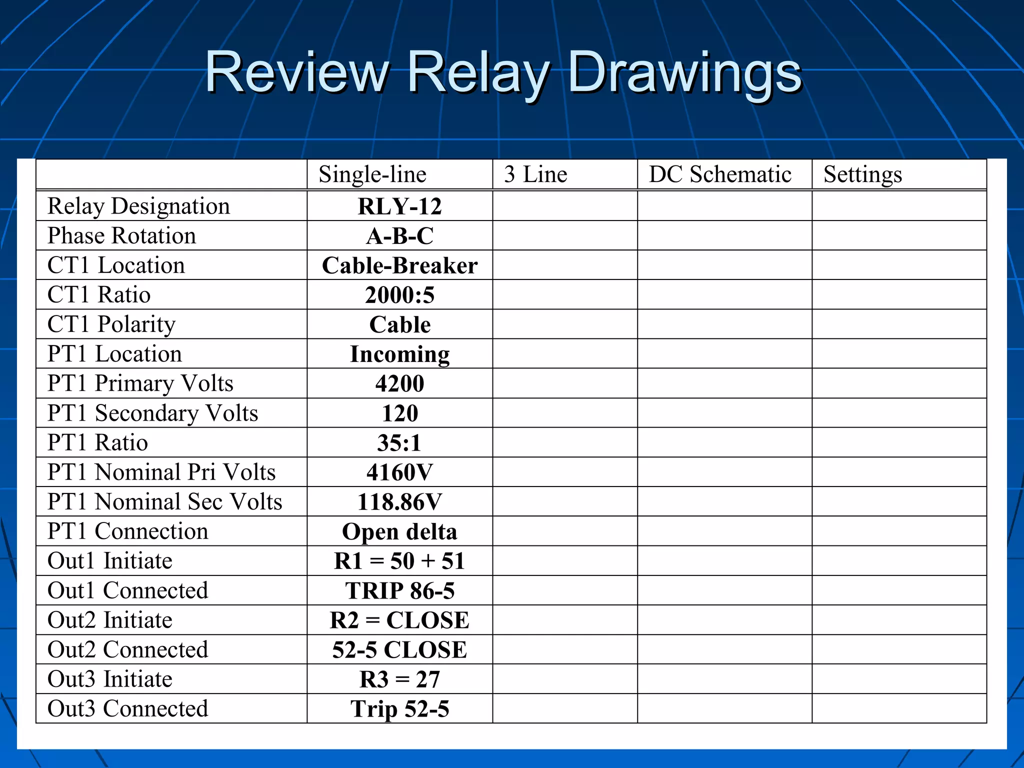
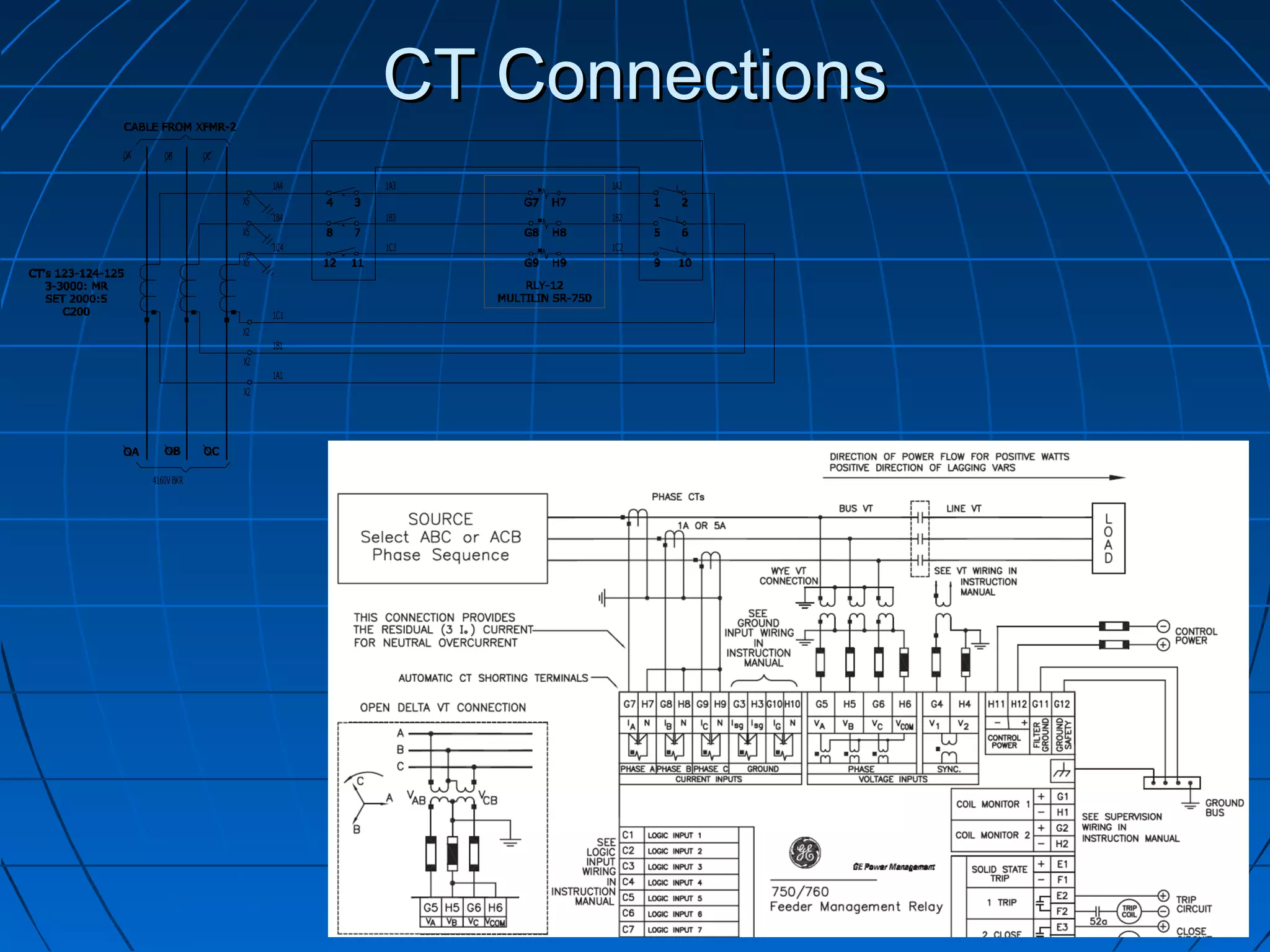
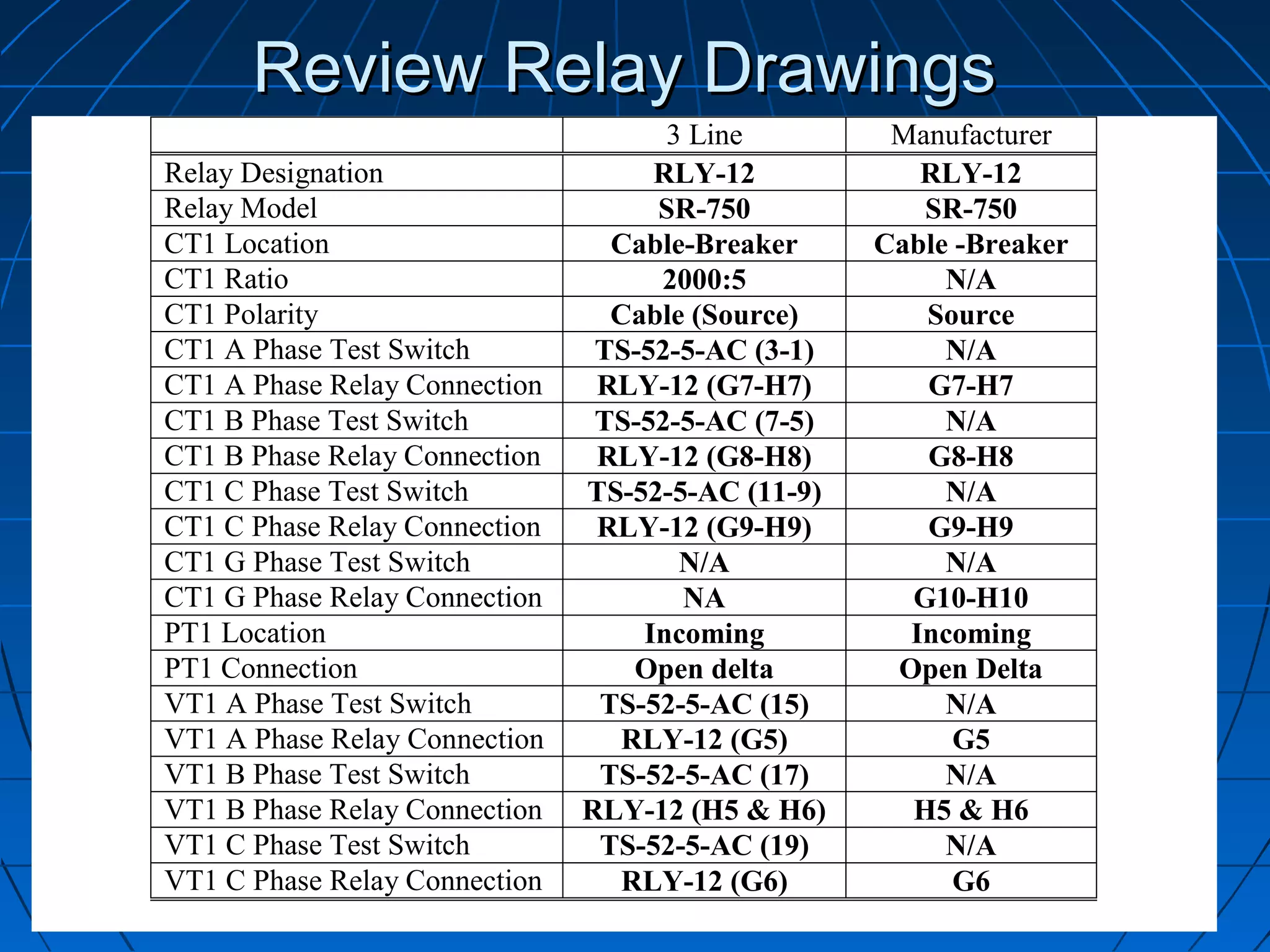
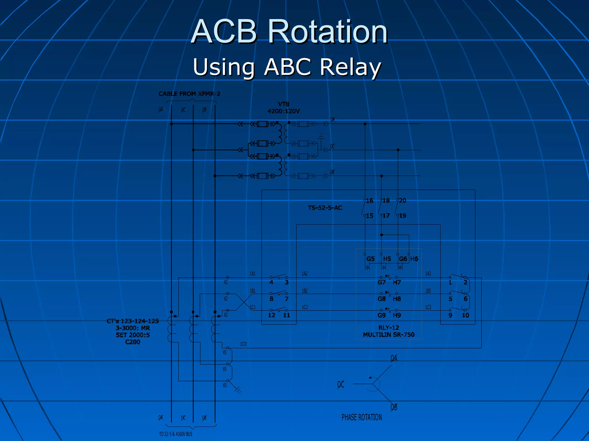
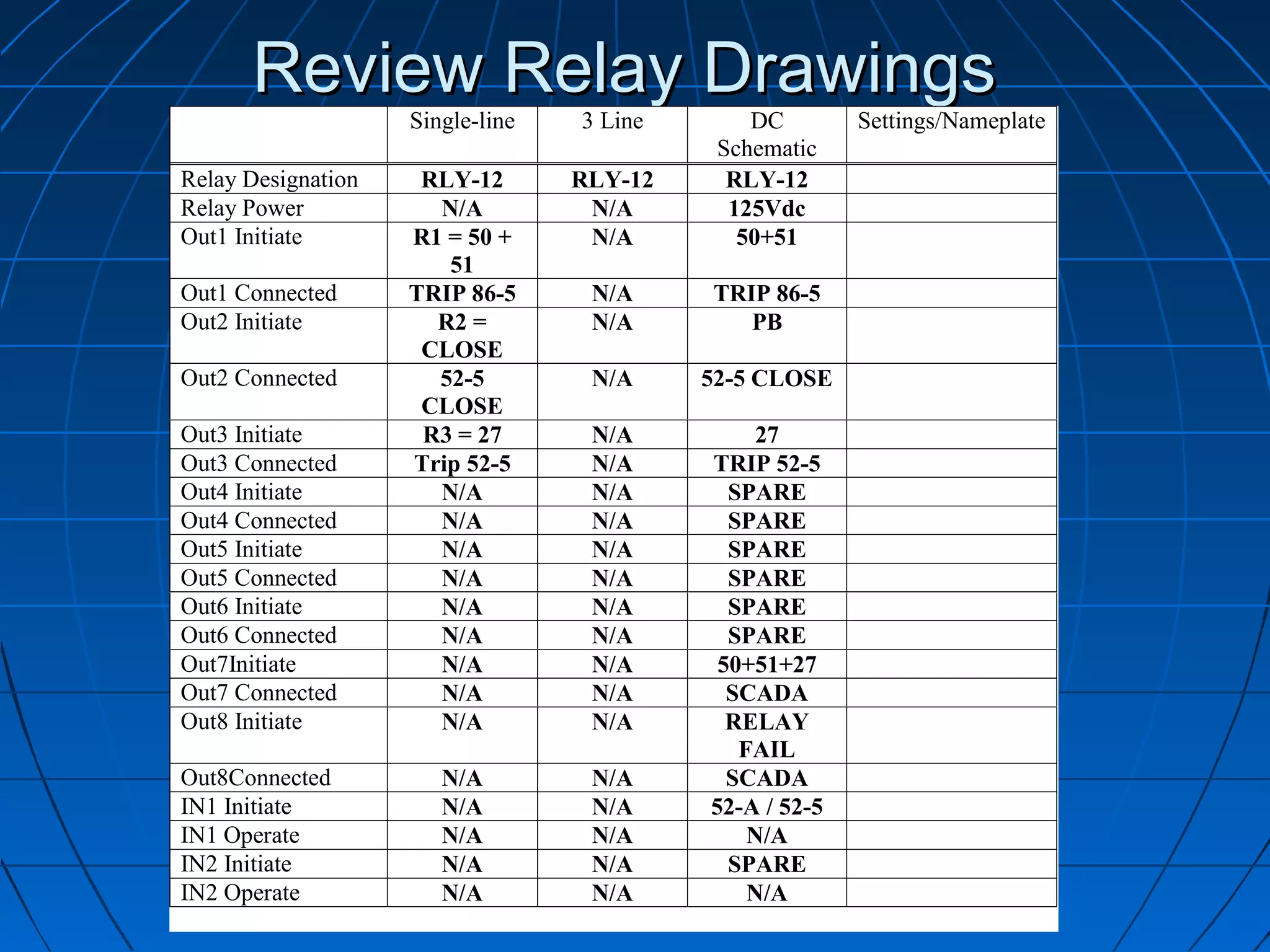
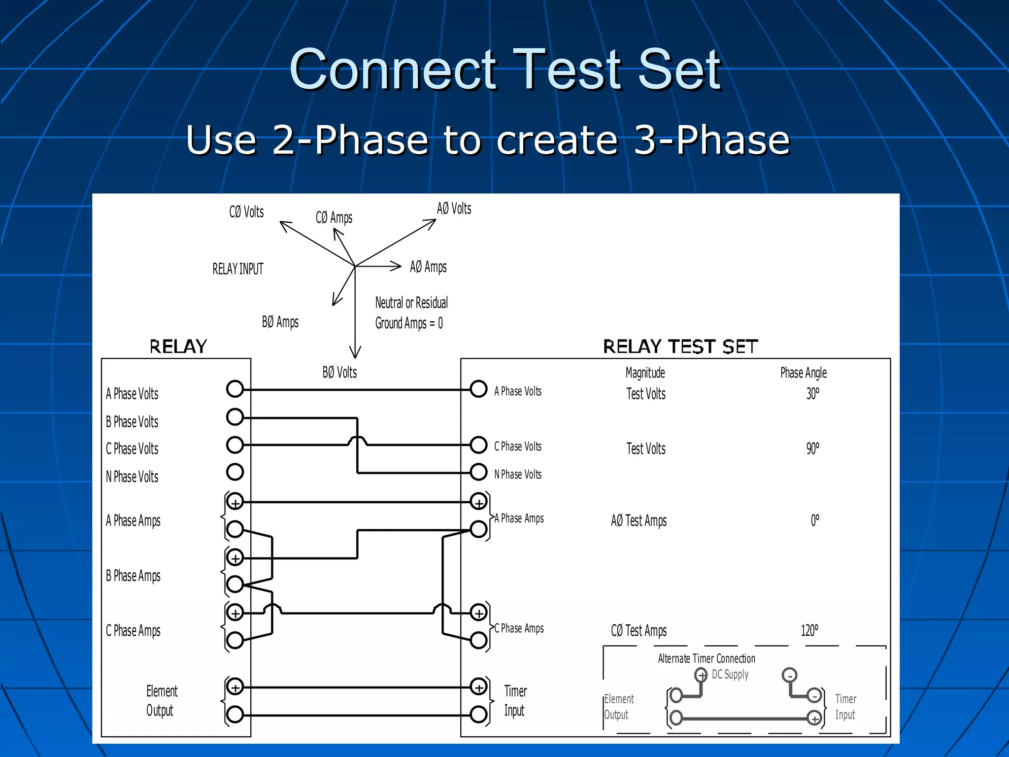
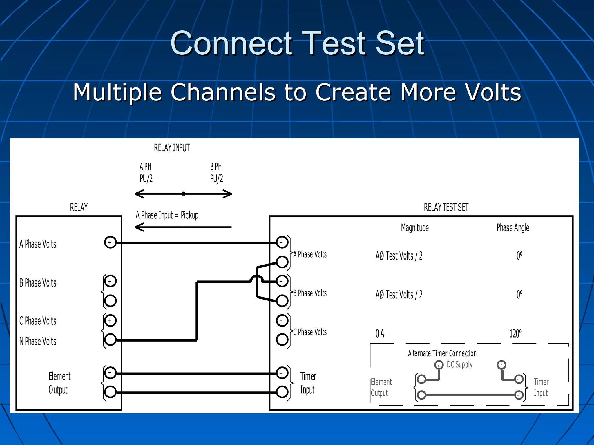
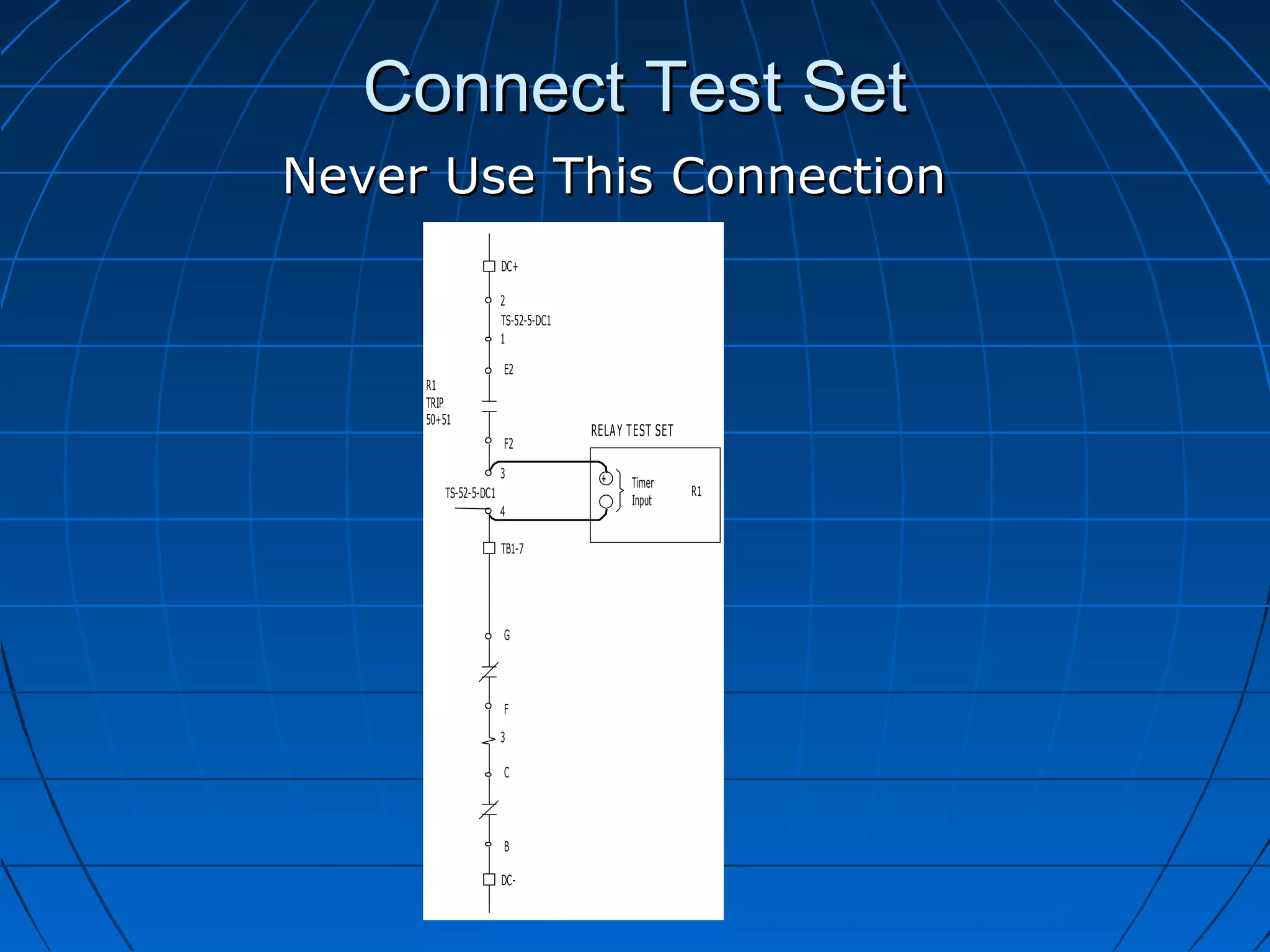
SlideShare a Scribd company logo
How to Create and
Implement Protective Relay
       Test Plans
       Chris Werstiuk


       www.valenceonline.com
Relay Testing Comments
          Percentage of Comments


                        3.57
                 7.79      5.84
                                      Design/Wiring
                               4.62
                                      Documentation
                                      Installation
                                      Relay
                                      Settings
  78.18


          www.valenceonline.com
Relay Testing Comments
                           Relay Comments


30
25
20
15
10
5
0
     Installation   Mechanical Failure   Operation   Part Number


                    www.valenceonline.com
Relay Testing Comments
                  Installation Comments


 40
 35
 30
 25
 20
 15
 10
  5
  0
      Labelling        Operation          Wiring


           www.valenceonline.com
Relay Testing Comments
                         Setting Comments

350

300

250

200

150

100

50

 0
      Re


                    AC


                                           Dr


                                                              Se


                                                                            O
                              An


                                                                             pe
                                              aw


                                                                tti
                                nu
         du


                     In


                                                                                r
                                                                   ng


                                                                                  at
                                                 in
            nd


                                nc
                       pu


                                                                                    io
                                                   g


                                                                     s/
                                   ia
              an


                         ts


                                                                                      n
                                                                    No
                                                   Co
                                     tio
                t


                                                                      tP
                                                      nf
                                     n


                                                        lic
                                       Pr


                                                                        ro
                                                        t
                                         ob


                                                                          vid
                                           le


                                                                             ed
                                             m


                    www.valenceonline.com
Types of Relay Testing
   Acceptance
   Commissioning
   Maintenance


             www.valenceonline.com
Introduction
   Review Relay application
   Establish Communication
   Connect Relay Set
   Create Test Plan
   Element Testing
   Logic Testing
   Final Report

             www.valenceonline.com
Review Relay Application
   CT Polarity and Location
   CT/PT Connections
   CT/PT Ratios
   CT/PT Test Points
   Output Connections
   Input Connections
   Power Supply Voltage
   Element Settings


              www.valenceonline.com
Review Relay Drawings
   Single Line Drawings


                      0.5A                       15A


                                  50        51         27
                             TS                                  TS


                                       TS                             TS


                                                                           M
                                                            TS
               52-5
Review Relay Drawings
   Single Line Drawings –CT Ratio
                                                                       Multilin SR-750
           0.5A                       15A
                                                                       2000:5 CT Ratio
                  TS
                       50        51         27
                                                      TS
                                                                       CT Polarity
                                                                        PT Ratio 4200:120
                            TS                             TS


                                                                M
                                                                    
                                                 TS
    52-5


                                                                       Test Switches
                                                                       50, 51, 27 Elements
                                                                       No Ground or Neutral


                                                      www.valenceonline.com
Review Relay Drawings
                                                                                               Multilin SR-750
                                                                                               2000:5 CT Ratio
                                                                                                CT Polarity
                      0.5A                                    15A
                                                                                            


                             TS
                                  50                    51          27
                                                                              TS
                                                                                               PT Ratio 4200:120
       CLOSE
                                  86
                                  -5
                                               TS                                  TS


                                                                                        M
                                                                                               Test Switches
                                                                                                50, 51, 27 Elements
               TRIP                                                      TS
52-5
                                                                                            
                                                         OA


                                                                                                No Ground or Neutral
                                   OC


                                       PHASE ROTATION
                                                         OB
                                                                                            

                                                                                               50/51 Trips 86
                                                                                               27 Trips Breaker
                                                                                               Close Function
Review Relay Drawings
                        Single-line     3 Line   DC Schematic   Settings
Relay Designation           RLY-12
Phase Rotation               A-B-C
CT1 Location            Cable-Breaker
CT1 Ratio                    2000:5
CT1 Polarity                 Cable
PT1 Location               Incoming
PT1 Primary Volts             4200
PT1 Secondary Volts            120
PT1 Ratio                     35:1
PT1 Nominal Pri Volts        4160V
PT1 Nominal Sec Volts       118.86V
PT1 Connection            Open delta
Out1 Initiate            R1 = 50 + 51
Out1 Connected            TRIP 86-5
Out2 Initiate            R2 = CLOSE
Out2 Connected           52-5 CLOSE
Out3 Initiate               R3 = 27
Out3 Connected             Trip 52-5
Review Relay Drawings
OA        OB        OC


                                                                            Multilin SR-750
                                            OA

                                                                        
                                            OB


                                            OC
                                                                           2000:5 CT Ratio
                                                                           CT Polarity
                         X2
                              1A1    1A2                          1A3
                                                                           PT Ratio 4200:120
                                                                            Test Switches
                              1B1    1B2                          1B3
                         X2


                         X2
                              1C1    1C2                          1C3   

                         X5


                         X5
                              1C0
                                                                           50, 51, 27 Elements
                                                                            No Ground or
                         X5
                                                                        
                                                             OA


                                           OC                               Neutral
                                                             OB
                                            PHASE ROTATION


OA        OB        OC

     TO 4160V BUS
Review Relay Drawings
                          Single-line       3 Line     DC Schematic Settings
Relay Designation           RLY-12         RLY-12
CT1 Location            Cable-Breaker   Cable -Breaker
CT1 Ratio                    2000:5         2000:5
CT1 Polarity                 Cable          Cable
PT1 Location               Incoming       Incoming
PT1 Primary Volts             4200           4200
PT1 Secondary Volts           120             120
PT1 Ratio                     35:1           35:1
PT1 Nominal Pri Volts        4160V          4160V
PT1 Nominal Sec Volts       118.86V        118.86V
                          (4160 / 35)
PT1 Connection            Open delta     Open Delta
Out1 Initiate            R1 = 50 + 51       N/A
Out1 Connected            TRIP 86-5         N/A
Out2 Initiate           R2 = CLOSE          N/A
Out2 Connected           52-5 CLOSE         N/A
Out3 Initiate               R3 = 27         N/A
Out3 Connected             Trip 52-5        N/A
CT Connections
OA      OB       OC

                           1A1         1A2    1A3
                      X2
                           1B1         1B2    1B3
                      X2
                           1C1         1C2    1C3
                      X2


                                 1C0
                      X5
                                 1B0
                      X5
                                 1A0
                      X5


     4160V BKR
CT Connections
OA           OB        OC

                                 1N1   1A3   1A2
                            X2
                                       1B3   1B2
                            X2
                                       1C3   1C2
                            X2


                                 1C1
                            X5
                                 1B1
                            X5
                                 1A1
                            X5


     CABLE FROM XFMR
CT Connections
OA      OB       OC

                           1A4   1A3   1A2
                      X5
                           1B4   1B3   1B2
                      X5
                           1C4   1C3   1C2
                      X5


                           1C1
                      X2
                           1B1
                      X2
                           1A1
                      X2


     4160V BKR
CT Connections
OA      OB       OC


                           1A4   1A3   1A2
                      X5
                           1B4   1B3   1B2
                      X5
                           1C4   1C3   1C2
                      X5


                           1C1
                      X2
                           1B1
                      X2
                           1A1
                      X2


     4160V BKR
PT Connections
    OA   OB   OC
                   OA


                   OB


                   OC
Review Relay Drawings
                                     3 Line         Manufacturer
Relay Designation                   RLY-12            RLY-12
Relay Model                         SR-750            SR-750
CT1 Location                     Cable-Breaker     Cable -Breaker
CT1 Ratio                           2000:5              N/A
CT1 Polarity                     Cable (Source)       Source
CT1 A Phase Test Switch         TS-52-5-AC (3-1)        N/A
CT1 A Phase Relay Connection    RLY-12 (G7-H7)        G7-H7
CT1 B Phase Test Switch         TS-52-5-AC (7-5)        N/A
CT1 B Phase Relay Connection    RLY-12 (G8-H8)        G8-H8
CT1 C Phase Test Switch        TS-52-5-AC (11-9)        N/A
CT1 C Phase Relay Connection    RLY-12 (G9-H9)        G9-H9
CT1 G Phase Test Switch               N/A               N/A
CT1 G Phase Relay Connection          NA             G10-H10
PT1 Location                       Incoming          Incoming
PT1 Connection                     Open delta       Open Delta
VT1 A Phase Test Switch         TS-52-5-AC (15)         N/A
VT1 A Phase Relay Connection      RLY-12 (G5)            G5
VT1 B Phase Test Switch         TS-52-5-AC (17)         N/A
VT1 B Phase Relay Connection   RLY-12 (H5 & H6)      H5 & H6
VT1 C Phase Test Switch         TS-52-5-AC (19)         N/A
VT1 C Phase Relay Connection      RLY-12 (G6)            G6
ACB Rotation
                      Using ACB Relay
OA          OC        OB
                                            OA


                                            OC


                                            OB


                                1A1   1A2                               1A3
                           X2
                                1C1   1C2                               1C3
                           X2
                                1B1   1B2                               1B3
                           X2


                                1C0
                           X5
                                                                   OA
                           X5

                           X5                    OC

                                                                   OB
OA          OC        OB                          PHASE ROTATION
TO 52-5 & 4160V BUS
ACB Rotation
                  Using ABC Relay
OA          OC        OB
                                                  OA


                                                  OC


                                                  OB


                                      1A1   1A2                               1A3
                           X2
                                      1B1   1B2                               1B3
                           X2
                                      1C1   1C2                               1C3
                           X2


                                1C0
                           X5
                                                                         OA
                           X5

                           X5                          OC

                                                                         OB
OA          OC        OB                                PHASE ROTATION
TO 52-5 & 4160V BUS
Test Switches
Voltage FT Switches


  www.valenceonline.com
Test Switches
Current FT Switches


  www.valenceonline.com
Test Switches
                                     Numbering
        1       3       5        7         9        11    13       15           17        19


    A       B       C        D         E        F         G        H        I         J
        2       4       6        8         10        12       14       16        18       20

   Odd numbers on top
   Relay CT Connection on top
   Relay PT connection Top and Bottom
   Shorting Bar on Left
   Test Probe Clips
Test Switches
GE PK2 Test Plugs
Test Switches
                                                                          Connections
                                                  RELAY                                                                                          RELAY
 PT        PT       PT                                                                        PT    PT       PT     PT                                                              PT
 A         B        C                                                                         N     A        B      C                                                               N

                         G PH     A PH                   B PH                 C PH                                        G PH     A PH              B PH                C PH


1      3        5         7       9      11         13          15       17          19            1        3      5      7   9         11         13          15       17          19
 A     B        C         D        E          F          G           H        I           J         A        B     C       D   E             F          G           H        I           J
2      4        6         8     10       12         14          16       18          20            2        4      6      8 10          12         14          16       18          20


                                  A PH                B PH                C PH                                                   A PH                   B PH                 C PH
                                                                 PH N                                                                                           PH N

                                                  FROM CTs                                                                                       FROM CTs

A PH            C PH                                                                               A PH            C PH
       B PH                                                                           N PH                  B PH

                                  FROM PTs                                                              FROM PTs


                                                                     www.valenceonline.com
Review Relay Drawings
    Relay Schematic


         SR750
         SR760
Review Relay Drawings
                                                                                                                    DC Outputs
             DC+


                                           TB1-6                TB1-8                   TB1-10           TB1-12


                                           2                    6                       10               14                                                                                               18
                   TS-52-5-DC1
                                           1                    5                       9                13                                                                                               17


                                                                                                                                                                                       TB1-3


                          E1                E2                   E3                      E4              F5                 E8                 F8                   E11                   E12                  H12
                       SOLID                 R1                       R2                  R3                                                                       R7                    R8
                                                                                                              R4                 R5                 R6                                           POWER
                       STATE                 TRIP                     CLOSE               AUX                                                                      AUX                   SELF
                                                                                                              AUX                AUX                AUX                                          SUPPLY
                       TRIP                  50+51                    PB                  27                                                                       50+51+27              TEST
                          F1                F2                   F3                      F4              F6                 F7                 F9                   F10                   F12                  H11
DC PANEL A
CT#3
125Vdc


                     SPARE


                                                                                                                    SPARE


                                                                                                                                       SPARE


                                           3                    7                       11               15                                                                                               19
                   TS-52-5-DC1
                                           4                    8                       12               16                                                                                               20


                                           TB1-7                TB1-9                   TB1-11           TB2-1                                                   TB1-4                 TB1-5
                                 DWG: 52-5 DC1
                                 TRIP 86-5


                                                     DWG: 52-5 DC2
                                                     52-5 CLOSE CKT


                                                                              DWG: 52-5 DC1
                                                                              52-5 TRIP CKT


                                                                                                 SPARE


                                                                                                                                                          DWG: SCADA-1
                                                                                                                                                          SCADA PT# 122
                                                                                                                                                          RELAY TRIPPED


                                                                                                                                                                              DWG: SCADA-1
                                                                                                                                                                              SCADA PT# 121
                                                                                                                                                                              RELAY FAIL ALARM


             DC-
Review Relay Drawings
  TB2-2
                                                                 DC Inputs
       39

             52A
             52-5             SPARE

       41

  TB2-3                               TB2-4


  2                                   6
                                               TS-52-5-DC2
  1                                   5


      C1                                  C2


                                                                     Wet Inputs
IN1                             IN2                   RLY-12
           DC
           NEG
                                                      MULTILIN   
                                                      SR-750
                        D12


                                                                    Dry Inputs
                    3
                         TS-52-5-DC2
                    4
Review Relay Drawings
                    Single-line   3 Line       DC        Settings/Nameplate
                                            Schematic
Relay Designation    RLY-12       RLY-12     RLY-12
Relay Power           N/A          N/A       125Vdc
Out1 Initiate       R1 = 50 +      N/A        50+51
                       51
Out1 Connected      TRIP 86-5      N/A     TRIP 86-5
Out2 Initiate         R2 =         N/A        PB
                     CLOSE
Out2 Connected        52-5         N/A     52-5 CLOSE
                     CLOSE
Out3 Initiate        R3 = 27       N/A          27
Out3 Connected      Trip 52-5      N/A     TRIP 52-5
Out4 Initiate         N/A          N/A       SPARE
Out4 Connected        N/A          N/A       SPARE
Out5 Initiate         N/A          N/A       SPARE
Out5 Connected        N/A          N/A       SPARE
Out6 Initiate         N/A          N/A       SPARE
Out6 Connected        N/A          N/A       SPARE
Out7Initiate          N/A          N/A      50+51+27
Out7 Connected        N/A          N/A       SCADA
Out8 Initiate         N/A          N/A       RELAY
                                              FAIL
Out8Connected          N/A         N/A       SCADA
IN1 Initiate           N/A         N/A     52-A / 52-5
IN1 Operate            N/A         N/A         N/A
IN2 Initiate           N/A         N/A       SPARE
IN2 Operate            N/A         N/A         N/A
Review Relay Drawings
       Searching DC Schematic
 DC+


                                                       TB1-10                    TB1-6


                                                      TS-86-1      TS-52-5-DC1   TS-52-5-DC1
           TB1-8          TB3-3           TB3-5

                   TS-
                   52-5
                   DC1

           DCS1

                                                  G
                                                      TS-86-1      TS-52-5-DC1   TS-52-5-DC1
           DCS2

                   TS-                                 TB1-11                    TB1-7
                   52-5
                   DC1

           TB1-9          TB3-4


                                                            52-5


                                  TB3-6


                                                       TB3-9                     TB3-11


 DC-
Review Relay Settings
            Common Problems
   CT Ratios Don’t Match
   PT Connections/Ratios Don’t Match
   Outputs Used But Not Assigned
   Outputs Assigned But Not Used
   Inputs Used But Not Assigned
   Inputs Assigned But Not Used
   Wrong Setting Version


              www.valenceonline.com
Review Relay Settings
                     Single-line    3 Line   DC Schematic Settings/Nameplate
Relay Designation     RLY-12       RLY-12      RLY-12           RLY-12
CT1 Ratio              2000:5      2000:5        N/A            2000:5
PT1 Ratio               35:1         35:1        N/A             35:1
PT1 Nominal Pri        4160V       4160V         N/A              N/A
Volts
PT1 Nominal Sec      118.86V       118.86V       N/A            118.9 V
Volts               (4160 / 35)
PT1 Connection      Open Delta      Open         N/A             Delta
                                    Delta
Relay Power             N/A         N/A        125Vdc          90-300Vdc
                                                            (From Namplate)
Out1 Initiate       R1 = 50 + 51    N/A        50+51          Trip = 50+51
Out1 Connected       TRIP 86-5      N/A       TRIP 86-5           N/A
Out2 Initiate           R2 =        N/A          PB              Close
                      CLOSE
Out2 Connected      52-5 CLOSE      N/A      52-5 CLOSE           N/A
Out3 Initiate         R3 = 27       N/A           27        Bus27-1+Bus27-2
Out3 Connected       Trip 52-5      N/A       TRIP 52-5           N/A
Out7Initiate            N/A         N/A       50+51+27       50+51+Bus27-1
                                                               +Bus27-2
Out7 Connected          N/A         N/A        SCADA              N/A
Out8 Initiate           N/A         N/A        RELAY              N/A
                                                FAIL
Out8Connected           N/A         N/A        SCADA             N/A
IN1 Initiate            N/A         N/A       52-A / 52-5        52-a
Review Co-ordination Study
                    CT Ratio
                    Pickup
                    Time Dial
                    Inst Pickup
                    Instantaneous Delay
                              OR
                    Check Pickup for
                     Upstream and
                     Downstream Relays


      www.valenceonline.com
Establish Communication
Rs-232
 Direct Serial Connection

 Null Modem


Rs-485
 Multiple Devices On One Network


Network
 TCP/IP

 192.168.1.1


              www.valenceonline.com
Apply Settings
   Hard Copy or Digital Copy
   Setting Version often Out of Date
   Document all discrepancies
   Report all discrepancies
   Changing Communication Port
    Settings
   Exit Program – re-enter and compare


             www.valenceonline.com
Connect Test Set
               Simulate CT/PT Connections
               3-Phase Connections Preferred
          RELA Y                                    RELA Y TEST SET
                                                      Magnitude                               Phase Angle
A Phase Volts                    A Phase Volts        Test Volts                                     0°
B Phase Volts                    B Phase Volts        Test Volts                           -120° (240°)
C Phase Volts                    C Phase Volts        Test Volts                                   120°
N Phase Volts                    N Phase Volts


A Phase Amps                     A Phase Amps     AØ Test Amps                                       0°


B Phase Amps                     B Phase Amps     BØ Test Amps                             -120° (240°)


C Phase Amps                     C Phase Amps     CØ Test Amps                                     120°
                                                              Alternate Timer Connection
                                                                            DC Supply
          Element                  Timer         Element                                                    Timer
          Output                   Input         Output                                                     Input
Connect Test Set
                    Use 2-Phase to create 3-Phase
                        CØ Volts                                     AØ Volts
                                         CØ Amps


                     RELAY INPUT                              AØ Amps

                                                     Neutral or Residual
                               BØ Amps               Ground Amps = 0


                                          BØ Volts                                                   Magnitude                            Phase Angle
A Phase Volts                                                                   A Phase Volts        Test Volts                                 30°
B Phase Volts
C Phase Volts                                                                   C Phase Volts        Test Volts                                 90°
N Phase Volts                                                                   N Phase Volts


A Phase Amps                                                                    A Phase Amps     AØ Test Amps                                    0°


B Phase Amps


C Phase Amps                                                                    C Phase Amps     CØ Test Amps                                 120°
                                                                                                             Alternate Timer Connection
                                                                                                                           DC Supply
          Element                                                                 Timer         Element                                                 Timer
          Output                                                                  Input         Output                                                  Input
Connect Test Set
    Multiple Channels to Create More Current
                    RELA Y INPUT

                   TS#1 TS#2 TS#2
                   PU/3 PU/3 PU/2

    RELA Y                                                         RELA Y TEST SET
                    A Pha se Input = Pick up
                                                                    Magnitude             Phase A ngle
               +                               +
A Phase Amps                                       A Phase Amps    AØ Test Amps / 3             0°

               +                               +
B Phase Amps                                       B Phase Amps    AØ Test Amps / 3             0°

               +                               +
C Phase Amps                                       C Phase Amps    AØ Test Amps / 3             0°
                                                                         A lternate T imer C onnec tion
                                                                                  D C Supply -


                                                                              +
               +                               +
    Element                                         Timer         E lement                      -
                                                                                                     T imer
    Output                                          Input         O utput                       +    I nput
Connect Test Set
                    Multiple Channels to Create More Volts

                                    RELAY INPUT
                             A PH                    B PH
                             PU/2                    PU/2

                RELAY                                                                                RELAY TEST SET
                            A Phase Input = Pickup
                                                                                          Magnitude                      Phase Angle
A Phase Volts           +                                   +
                                                                A Phase Volts    AØ Test Volts / 2                              0°

B Phase Volts           +                                   +
                                                                B Phase Volts    AØ Test Volts / 2                              0°

C Phase Volts           +                                   +
                                                                C Phase Volts    0A                                           120°
N Phase Volts
                                                                                            Alternate Timer Connection
                                                                                                           DC Supply      -


                                                                                                        +
                        +                                   +
          Element                                                 Timer         Element                                         -
                                                                                                                                       Timer
          Output                                                  Input         Output                                          +      Input
Connect Test Set
                   OA        OB        OC
                                                                                OA


                                                                                OB


                                                                                OC


                                                             ISOLATING DEVICE


                                                       1A1                                                                                                                       1C0
                                            X2                                                                                                                            2
                                                       1B1
                                            X2                                                G5          H5    G6          H6                                            6
                                                       1C1
                                                                                      1A2                                           1A3
                                            X2                                                                                                                            8
CT's 123-124-125                                                                 3                   G7        H7                                    1
3-3000: MR                                                                            1B2                                           1B3
SET 2000:5
C200                                                                             7                   G8        H8                                    5
                                                 1C0                                  1C2                                           1C3
                                            X5                                   11                  G9        H9                                    9

                                            X5

                                            X5


                                                                                                                    RELAY TEST SET
                                                                                                                            Magnitude                       Phase Angle
                                                                                            A Phase Volts                   Test Volts                            0°
                                                                                            B Phase Volts                   Test Volts                    -120° (240°)
                                                                                            C Phase Volts                   Test Volts                          120°
                                                                                            N Phase Volts

                                                                                            A Phase Amps                  AØ Test Amps                            0°
                   OA        OB        OC
                                                                                            B Phase Amps                  BØ Test Amps                    -120° (240°)
                        TO 4160V BUS

                                                                                            C Phase Amps                  CØ Test Amps                          120°
                                                                                                                             Alternate Timer Connection
                                                                                                                                            DC Supply
                                                                                             Timer              Element                                                  Timer
                                                                                             Input              Output                                                   Input
Connect Test Set
                   OA        OB        OC
                                                                                OA
                                                                                                                                                                                           Triple Check Voltage
                                                                                OB


                                                                                OC
                                                                                                                                                                                            Connections
                                                                                                                                                                                           Isolate CTs
                                                             ISOLATING DEVICE                                                                                                              Use a checklist when
                                                                                                                                                                                            removing Wires
                                                       1A1                                                                                                                        1C0
                                            X2                                                                                                                             2
                                                       1B1
                                            X2                                                 G5          H5    G6          H6                                            6
                                                       1C1
                                                                                      1A2                                            1A3
                                            X2                                                                                                                             8
CT's 123-124-125                                                                 3                    G7        H7                                    1
3-3000: MR                                                                            1B2                                            1B3
SET 2000:5
C200                                                                             7                    G8        H8                                    5
                                                 1C0                                  1C2                                            1C3
                                            X5                                   11                   G9        H9                                    9

                                            X5

                                            X5


                                                                                                                     RELAY TEST SET
                                                                                                                             Magnitude                       Phase Angle
                                                                                             A Phase Volts                   Test Volts                            0°
                                                                                             B Phase Volts                   Test Volts                    -120° (240°)
                                                                                             C Phase Volts                   Test Volts                          120°
                                                                                             N Phase Volts

                                                                                             A Phase Amps                  AØ Test Amps                            0°
                   OA        OB        OC
                                                                                             B Phase Amps                  BØ Test Amps                    -120° (240°)
                        TO 4160V BUS

                                                                                             C Phase Amps                  CØ Test Amps                          120°
                                                                                                                              Alternate Timer Connection
                                                                                                                                             DC Supply
                                                                                              Timer              Element                                                  Timer
                                                                                              Input              Output                                                   Input


                                                                                                www.valenceonline.com
Connect Test Set
Simple Relay Output Connections
                           TB1-6


                           2
   TS-52-5-DC1
                           1


                                                                                           125V+
                                                                                           TB1-3


                                           RELAY TEST SET                                                   RELAY TEST SET
                            E2                                   E11                     E12
                                   R1                                  R7                            R8
                                   TRIP      +                         AUX                           SELF     +
                                                   Timer                                                            Timer
                                   50+51                               50+51+27                      TEST
                                                   Input                                                            Input
                            F2                                   F10                     F12


                           3
   TS-52-5-DC1
                           4


                           TB1-7                                   TB1-4                   TB1-5
                 DWG: 52-5 DC1
                 TRIP 86-5


                                                            DWG: SCADA-1
                                                            SCADA PT# 122
                                                            RELAY TRIPPED


                                                                                  DWG: SCADA-1
                                                                                  SCADA PT# 121
                                                                                  RELAY FAIL ALARM
Connect Test Set
        Parallel Output Connections
TB1-8                                                TB1-8

                6 TS-                                                6 TS-
                  52-5                                                 52-5
                5 DC1                                                5 DC1
                           RELAY TEST SET                                     RELAY TEST SET
DCS1            E3                                   DCS1            E3
                 R2                                                   R2
DCS                                         STATUS   DCS                                       STATUS
                 CLOSE       +                                        CLOSE     +
CLOSE                              Timer             CLOSE                            Timer
                 PB                         CLOSED                    PB                         OPEN
                                   Input                                              Input
DCS2            F3                                   DCS2            F3

                7 TS-                                                7 TS-
                  52-5                                                 52-5
                8 DC1                                                8 DC1

TB1-9                                                TB1-9


TB1-8                                                TB1-8


                           RELAY TEST SET                                     RELAY TEST SET
DCS1            E3                                   DCS1            E3

        DCS     R2                          STATUS           DCS     R2                        STATUS
        CLOSE   CLOSE        +
                                   Timer                     CLOSE   CLOSE      +
                                                                                      Timer
                PB                          OPEN                     PB                          OPEN
                                   Input                                              Input
DCS2            F3                                   DCS2            F3

                7 TS-
                  52-5
                8 DC1

TB1-9                                                TB1-9
Connect Test Set
Using Voltage for Contact Sensing
              DC+


                                                                                                                                  TB1-10                                               TB1-6

                                                                                                                              2                         10                             2
                                                                                                                                  TS-86-1                    TS-52-5-DC1               TS-52-5-DC1
                                           TB1-8                    TB3-3                            TB3-5                    1                         9                              1
                                                                                                                                                                           11
                                                           6 TS-                                                              E2                        E4                             E2
                                                             52-5                                                                                       R3                                      R1
                                                           5 DC1                                                                                        AUX                     CS              TRIP
                                                                                                                                  86-5
                                                                                                                                                        27                      TRIP            50+51
                                                                     16                                           +
                                           DCS1            E3                                                                 F2                        F4                             F2
                                                           R2                                                                                                              18
                                           DCS             CLOSE    CS
                                                                                                              G               3                         11                             3
                                           CLOSE           PB       CLOSE
                                                                                                                                  TS-86-1                    TS-52-5-DC1               TS-52-5-DC1
                                           DCS2            F3                                                                 4                         12                             4
                                                                     17                                           -
                                                           7 TS-
                                                                                                                                  TB1-11                                               TB1-7
                    RELAY TEST SET                           52-5
                                                           8 DC1

                               Timer   +   TB1-9                    TB3-4
                      R2
                               Input
                                           52                        22
                                                                                                                                   RELAY TEST SET                                                       RELAY TEST SET
                                                    43                      43
                                                    AUTO                    MANUAL                                                                           +                                            +
                                                                                                                                                Timer                                                           Timer
                                                                                                                                    R3                                                                                   R1
                                                                                                                                                Input                                                           Input
                                           53                        21

                                           11


                                                   86-5
 DC PANEL A
 CT#4
 125Vdc


                                           13

                                           1                                         1

                                                   52-5                                       52-5
                                                   TOC                                        TOC

                                           2                                         2

                                                                                     3               7                8            18

                                                                                         SR              M                               TRIP

                                                                                         Y               LS               b         a
                                                                                                                                                                                       G
                                                                                Y        LS

                                                                                         b
                                                                                                                                          52-5                                         F

                                                                                     4                                             17                                                           86-5
                                                                                                                                                                                       C

                                                                                     TB3-6

                                                                                                                                                                                       B

                                                                                                                                  TB3-9                                                TB3-11


              DC-
Connect Test Set
Never Use This Connection
                      DC+

                      2
                      TS-52-5-DC1
                      1

                      E2
     R1
     TRIP
     50+51
                                    RELA Y TEST SET
                      F2

                      3              +
                                           Timer
        TS-52-5-DC1                                   R1
                                           Input
                      4

                      TB1-7


                      G


                      F
                      3

                      C


                      B

                      DC-
Connect Test Set
             Input Connections
              DC+


                          TB2-2                                                       RELAY TEST SET

                          39
                                                                                        +

                               52A                                                             Test


                                                   SPARE
                               52-5                                                            Output

                          41

                          TB2-3                            TB2-4


                          2                                6
                                                                    TS-52-5-DC2
                          1                                5
DC PANEL A
CT#3
125Vdc


                              C1                               C2
                    IN1                            IN2                     RLY-12
                                   DC                                      MULTILIN
                                   NEG
                                                                           SR-750
                                             D12


                                         3
                                              TS-52-5-DC2
                                         4


              DC-
Create The Test plan
   Collect all charts
   Review enabled elements
   Outputs include contacts,
    communication, and LEDs
   Work backward using outputs


             www.valenceonline.com
Create The Test plan
   Look for conflicts
   How to monitor pickup
    •   LEDs
    •   Contact
    •   Front panel
    •   Communication
    •   Timing test

      Element        Pickup              Curve         Time Dial     Relays
     51 (TOC)      1xCT (5.0A)    Normally Inverse       3.00      Trip & R7
                                          (NI)
    50 (IOC) #1     9xCT (45A)    Definite Time (DT)    0.10 s     Trip & R7
    27 (BUV) #1   0.9xVT (108V)            DT           60.0s       R3 & R7
    27 (BUV) #2      0.85xVT               DT           20.0s       R3 & R7
                      (102V)
Create The Test plan
                  Testing Order
   How to disable settings, when absolutely
    necessary
   Disable 51, Test 50, Enable 51, Test 51
   Disable 27-1, Test 27-2, Enable 27-1, Test
    27-1

      Element        Pickup              Curve         Time Dial     Relays
     51 (TOC)      1xCT (5.0A)    Normally Inverse       3.00      Trip & R7
                                          (NI)
    50 (IOC) #1     9xCT (45A)    Definite Time (DT)    0.10 s     Trip & R7
    27 (BUV) #1   0.9xVT (108V)            DT           60.0s       R3 & R7
    27 (BUV) #2      0.85xVT               DT           20.0s       R3 & R7
                      (102V)
Create The Test plan
                  Testing Order
   Test Without Setting Changes
   Test 51, Use timing test for 50 pickup tests
   Test 27-1 pickup with LED, 27-2 pickup
    with timing or communication
   Time tests not affected
      Element        Pickup              Curve         Time Dial     Relays
     51 (TOC)      1xCT (5.0A)    Normally Inverse       3.00      Trip & R7
                                          (NI)
    50 (IOC) #1     9xCT (45A)    Definite Time (DT)    0.10 s     Trip & R7
    27 (BUV) #1   0.9xVT (108V)            DT           60.0s       R3 & R7
    27 (BUV) #2      0.85xVT               DT           20.0s       R3 & R7
                      (102V)
Create The Test plan
   Think about your objective…Be Creative
   Don’t follow dogmatic approach for testing
   Electromechanical Overcurrent Dogma
    • Pickup A, B, C Phase
    • Timing test @ 2,4,6x on A, B, C
   Digital Overcurrent Testing
    •   Pickup A, B, C Phase
    •   1st timing test on A
    •   2nd timing test on B
    •   3rd timing test on C
    •   1 more test to check for reset
Create The Test plan
                  Generator Protection
   Disable 27, 46, 27, 27TN, 24, 50BF, 50/27
   Test 21, 40, 32, 51V
   Enable and test 46
   Test 59
   Enable and test 24
   Test 81
   Enable and test 50/27
   Enable and test 50BF
   Enable and test 87
   Test 59N
   Enable and test 27TN
   Enable and test 27
Create The Test plan
               Distance Protection
   Test Zone 1,2,3 Pickup with 3 Phase
   Test Zone 1,2,3 Timing using Phase-Phase
   Test Zone 1,2,3 Pickup and Timing with
    Phase-Neutral
   Test overcurrent Protection


               www.valenceonline.com
Create The Test plan
               Evaluating Results
   Percent Error
    Actual Value - Expected Value
                                                  X 100 = percent error
             Expected Value

    Relay Specifications
    Device                        Setpoint
    Number    Function            Ranges          Increment    Accuracy
             50W1/50W2                                        +/- 0.1 A or +/- 3%
     50      Pickup #1, #2      1.0 to 100.0 A       0.1 A    (+/- 0.02 A or +/- 3%)
                                (0.2 to 20.0 A)
             Trip TIme Response Fixed 2 Cycles        -       +/- 2 Cycles


                             www.valenceonline.com
Create The Test plan
                     Evaluating Results
   Relay Specifications for Small Time Delays
               Instantaneous/Definite-Time Overcurrent Elements

         Pickup Range:                 OFF, 0.25 - 100.00 A, 0.01 A steps (5 A nominal)
                                       OFF, 0.05 - 20.00 A, 0.01 A steps (1 A nominal)
         Steady State Pickup Accuracy: +/- 0.05 A and +/-3% of Setting (5 A nominal)
                                       +/- 0.01 A and +/-3% of Setting (1 A nominal)

         Transient Overreach:          < 5% of Pickup

         Time Delay:                   0.00 - 16,000.00 cyc les, 0.25-cyc le steps
         Timer Accuracy:               +/- 0.25 cycle and +/-0.1% of setting

        Output Contacts:            30 A Make
                                    6A c ontinuous carry at 70 C; 4 A continuous carry at 85 C
                                    50A for one second
                                    MOV Protected: 270 Vac, 360 Vdc , 40 ; Pickup Time: <5ms.

                       MANTA MTS-1710 TIME MEASUREMENT SPECIFICATIONS
             Auto ranging Scale:            0 – 99999 sec
             Auto ranging Scale:            0 – 99999 cycles
             Best Resolution:               0.1 ms / 0.1 cycles
                                            Two wire pulse timing mode
             Accuracy:                      0 – 9.9999 sec scale: +/-0.5ms +/- 1LS digit
                                            all other scales: +/- 0.005% +/- 1 digit
Create The Test plan
                     Evaluating Results
   Relay Specifications for Small Time Delays
                                 Minimum Time Test Result
        Relay Operate Time:          0.25 cycles
        Relay Timing Accuracy:       0.10 cycles (0.1% of setting, because setting is zero
                                                  and next setting is 1 cycle, use 0.1
                                                  cycles)
        Relay Operate Time:          0.30 cycles (< 5 ms)
        Test Set :                   0.03 cycles (+/-0.005%)
                                     1.00 cycles (+/- 1LS digit)
                                     1.68 cycles or 0.28 ms


                         www.valenceonline.com
Test the Relay
                    Self Tests
   What do self tests check?
   Perform and document self-tests

                     Outputs
   Pulse all or unused outputs

                     Inputs
   Check Status of all or unused inputs


                www.valenceonline.com
Test the Relay
Input / Output Tests


 www.valenceonline.com
Test the Relay
            Metering or Analog Inputs
   2x Single Phase to Verify Connections
   3 Phase for metering
   Phase angles and/or Watts and VARs to
    check connections
   Positive, negative, and zero sequence
                         LEADING PHASE ANGLES                                     LAGGING PHASE ANGLES

                                                                                                 270
                                         90                                                                300
                                                 60                                              -90
                           120                                                    240                    -60
                                                                                    -120
                             Vbn                                                      Vbn


                                                                                                                 330
                                                          30


                                                                                                                   -30
                                                                         210
                150


                                                                       -150

         180                                                         180
                                                         Van     0                                               Van     0
         -180                                                        -180
                                                                            150
                210


                                                           330


                                                                                                                 30
                  -150


                                                        -30


                               Vbn                                                      Vbn
                            240
                         -120                   300                               120
                                                                                                           60
                                        270       -60
                                                                                                  90
                                        -90
Test the Relay
Voltage / Current Tests
Test The Relay
                   Test for Pickup
    Apply value above pickup and check
    Apply value lower than pickup
    Use ramp method for currents below 10A
    Use Jogging Method for currents above 10A

5A         ELEMENT PICK-UP    5A       ELEMENT PICK-UP
4A                            4A
3A                  PICK UP   3A                PICK UP
2A                            2A
1A                            1A

STEADY-STATE PICK-UP TEST      JOGGING PICK-UP TEST
Test The Relay
                                          Timing Tests
   Use Dynamic Testing
   At least two points for Curves
   At least 10% higher for Instantaneous


                   TEST IN PROGRESS                                 TEST IN PROGRESS
                                                    150 V
    150 V
                                          PICK UP   120 V
    120 V                                            90 V                                    PICK UP
     90 V                                            60 V
     60 V                                            30 V
     30 V
                                                            0   1    2   3   4   5   6   7
            0     1 2 3 4 5      6    7
                TIME IN CYCLES
Test The Relay
       General Tips and Tricks for Problems
   Check metering if test doesn’t work
   Pulse Contact to test connections
   Has a lead fallen off?
   All channels have same phase angle when
    paralleling?
   Blocking Inputs?
   Another function required for operation?


               www.valenceonline.com
Test The Relay
             Tips and Tricks for 50/51
   Use 3 phases to bypass Neutral Protection
   Perform phase to phase tests to bypass
    neutral protection
   Apply all 3 currents at same angle to
    bypass phase protection


               www.valenceonline.com
Test The Relay
      Tips and Tricks for Voltage Elements
   Always use pre-fault voltage
   Some relays require current for voltage
    detection
   Check your sequence components


                www.valenceonline.com
Test The Relay
     Tips and Tricks for Impedance Elements
   Always use pre-fault values
   Check for LOP operation
   Test pickup with 3-phase
   Use a lower voltage for lower current
    pickup
   Check fault detector operation
   Timing can be affected by communication
    schemes


               www.valenceonline.com
Test The Relay
                Final Output Tests
   Most important part of relay testing
   Treat as electrical schematic
   Reduce logic to base components
   Prove Each Combination
Test The Relay
                               Final Output Tests
       R1 - TRIP               R2 - CLOSE        R3 - AUX                          R7 - AUX

      50P + 51P                                       27                    50P + 51P + 27


                                                                      50P
50P                                         27
                   R2                                 OR         R3   51P              OR           R7
            OR
51P
                                                                      27

                               CLOSE
                               PUSHBUTTON


            50P         51P                                 27              50P               51P        27


      R2                                             R3                                R7
Test The Relay
                Final Output Tests
   SV1 = (SV1 + IN201) * (50P1 + 50G1)
   SV1PU = 10
   SV1DO = 10             SV1 = (SV1 + IN201) * (50P1 + 50G1)
                                                                                  SV1
                                                                                         IN
                                                                                         201
                                                                                                      SV1

   50P1P = 0.25
   50G1P = 0.25
                     SV1
                                      OR                                          50G    50N
                  IN201

    IN201 = TRIPS FROM OTHER RELAY
                    50P1
                          AND
                                                                 10cycles
                                                                            SV1

                                      OR
                   50G1

                                                                                   SV1         SV1T     10cycles
Test The Relay
                 Final Output Tests
   Wait till end and perform 1 timing test for
    each element
   Combine output logic with element testing
    • No Setting Changes with this method
    • Perform 1 timing test on each contact
Prepare the Relay For Service
   Set Time and Date
   Clear Event Recorder
   Clear Fault Records
   Reset Targets
   Clear Metering Minimums/Maximums
   Save Settings


              www.valenceonline.com
Final Report
   Cover Letter
    •   Project History
    •   Scope of Work
    •   Summary of Problems and Actions
    •   Written for non-technical
    •   Justify your work!!
   Test Sheet
    •   Notes
    •   Test Results
    •   Expected Result
    •   Pass / Fail
Final Report
   Final Settings
    • Save disc of all settings in native format
    • Print all settings in adobe or hard copy for
      anybody to review.


                  www.valenceonline.com
Questions???

   www.valenceonline.com

More Related Content

What's hot

Unit 1 electric drive
Unit 1 electric driveUnit 1 electric drive
Unit 1 electric drive
raviarmugam
 
Transmission line Project
Transmission line ProjectTransmission line Project
Transmission line Project
Pankaj Kumar Dwivedi
 
Electric substation
Electric substation Electric substation
Electric substation
ANNU KUMAR
 
Substation equipments & its functions
Substation equipments & its functionsSubstation equipments & its functions
Substation equipments & its functions
Monzer Abdallah Eisa
 
Automotive Driver Requirements Topologies & Applications
Automotive Driver Requirements Topologies & ApplicationsAutomotive Driver Requirements Topologies & Applications
Automotive Driver Requirements Topologies & Applications
ON Semiconductor
 
Electrical Safety in Power System Distribution
Electrical Safety in Power System DistributionElectrical Safety in Power System Distribution
Electrical Safety in Power System Distribution
Eze , Monday Ndubuisi
 
HT and LT SWITCHGEAR
HT and LT SWITCHGEARHT and LT SWITCHGEAR
HT and LT SWITCHGEAR
Ravindra Kumar
 
EHVAC transmission line maintenance techniques
EHVAC transmission line maintenance techniquesEHVAC transmission line maintenance techniques
EHVAC transmission line maintenance techniques
Yashwant Chaudhari
 
Lecture-PS-faults-description-recorded-30032020-110109pm.pptx
Lecture-PS-faults-description-recorded-30032020-110109pm.pptxLecture-PS-faults-description-recorded-30032020-110109pm.pptx
Lecture-PS-faults-description-recorded-30032020-110109pm.pptx
Muhammad Junaid
 
Switchgear Equipment in a Substation
Switchgear Equipment in a SubstationSwitchgear Equipment in a Substation
Switchgear Equipment in a Substation
Md. Atiqur Rahman
 
Generator protection
Generator protectionGenerator protection
Generator protection
Keshar Rawal
 
Substation design-guideliness
Substation design-guidelinessSubstation design-guideliness
Substation design-guideliness
OSMAN SAYGIN AKKAYA
 
Simple Disconnector Switch (DS) Testing for Switchyard Equipment
Simple Disconnector Switch (DS) Testing for Switchyard EquipmentSimple Disconnector Switch (DS) Testing for Switchyard Equipment
Simple Disconnector Switch (DS) Testing for Switchyard Equipment
SARAVANAN A
 
Difference between grounding and earthing
Difference between grounding and earthingDifference between grounding and earthing
Difference between grounding and earthing
Dr.Raja R
 
Tender Document for 1 MW Solar at Daman
Tender Document for 1 MW Solar at DamanTender Document for 1 MW Solar at Daman
Tender Document for 1 MW Solar at Daman
Headway Solar
 
Lightning, Surge Protection & Earthing of Electrical & Electronic Systems in ...
Lightning, Surge Protection & Earthing of Electrical & Electronic Systems in ...Lightning, Surge Protection & Earthing of Electrical & Electronic Systems in ...
Lightning, Surge Protection & Earthing of Electrical & Electronic Systems in ...
Living Online
 
Case Study - Importance of Relay Coordination in Process Industries
Case Study - Importance of Relay Coordination in Process IndustriesCase Study - Importance of Relay Coordination in Process Industries
Case Study - Importance of Relay Coordination in Process Industries
System Protection
 
Case Study - How we saved a Process Plant from break-down
Case Study - How we saved a Process Plant from break-downCase Study - How we saved a Process Plant from break-down
Case Study - How we saved a Process Plant from break-down
System Protection
 
switching substation, plcc and scada
switching substation, plcc and scadaswitching substation, plcc and scada
switching substation, plcc and scada
Hemendra Kumar Rajput
 
Normas regulamentosinstalaçõeselétricas
Normas regulamentosinstalaçõeselétricasNormas regulamentosinstalaçõeselétricas
Normas regulamentosinstalaçõeselétricas
Claudio Trancoso Rodrigues
 

What's hot (20)

Unit 1 electric drive
Unit 1 electric driveUnit 1 electric drive
Unit 1 electric drive
 
Transmission line Project
Transmission line ProjectTransmission line Project
Transmission line Project
 
Electric substation
Electric substation Electric substation
Electric substation
 
Substation equipments & its functions
Substation equipments & its functionsSubstation equipments & its functions
Substation equipments & its functions
 
Automotive Driver Requirements Topologies & Applications
Automotive Driver Requirements Topologies & ApplicationsAutomotive Driver Requirements Topologies & Applications
Automotive Driver Requirements Topologies & Applications
 
Electrical Safety in Power System Distribution
Electrical Safety in Power System DistributionElectrical Safety in Power System Distribution
Electrical Safety in Power System Distribution
 
HT and LT SWITCHGEAR
HT and LT SWITCHGEARHT and LT SWITCHGEAR
HT and LT SWITCHGEAR
 
EHVAC transmission line maintenance techniques
EHVAC transmission line maintenance techniquesEHVAC transmission line maintenance techniques
EHVAC transmission line maintenance techniques
 
Lecture-PS-faults-description-recorded-30032020-110109pm.pptx
Lecture-PS-faults-description-recorded-30032020-110109pm.pptxLecture-PS-faults-description-recorded-30032020-110109pm.pptx
Lecture-PS-faults-description-recorded-30032020-110109pm.pptx
 
Switchgear Equipment in a Substation
Switchgear Equipment in a SubstationSwitchgear Equipment in a Substation
Switchgear Equipment in a Substation
 
Generator protection
Generator protectionGenerator protection
Generator protection
 
Substation design-guideliness
Substation design-guidelinessSubstation design-guideliness
Substation design-guideliness
 
Simple Disconnector Switch (DS) Testing for Switchyard Equipment
Simple Disconnector Switch (DS) Testing for Switchyard EquipmentSimple Disconnector Switch (DS) Testing for Switchyard Equipment
Simple Disconnector Switch (DS) Testing for Switchyard Equipment
 
Difference between grounding and earthing
Difference between grounding and earthingDifference between grounding and earthing
Difference between grounding and earthing
 
Tender Document for 1 MW Solar at Daman
Tender Document for 1 MW Solar at DamanTender Document for 1 MW Solar at Daman
Tender Document for 1 MW Solar at Daman
 
Lightning, Surge Protection & Earthing of Electrical & Electronic Systems in ...
Lightning, Surge Protection & Earthing of Electrical & Electronic Systems in ...Lightning, Surge Protection & Earthing of Electrical & Electronic Systems in ...
Lightning, Surge Protection & Earthing of Electrical & Electronic Systems in ...
 
Case Study - Importance of Relay Coordination in Process Industries
Case Study - Importance of Relay Coordination in Process IndustriesCase Study - Importance of Relay Coordination in Process Industries
Case Study - Importance of Relay Coordination in Process Industries
 
Case Study - How we saved a Process Plant from break-down
Case Study - How we saved a Process Plant from break-downCase Study - How we saved a Process Plant from break-down
Case Study - How we saved a Process Plant from break-down
 
switching substation, plcc and scada
switching substation, plcc and scadaswitching substation, plcc and scada
switching substation, plcc and scada
 
Normas regulamentosinstalaçõeselétricas
Normas regulamentosinstalaçõeselétricasNormas regulamentosinstalaçõeselétricas
Normas regulamentosinstalaçõeselétricas
 

Viewers also liked

Relay testing procedure
Relay testing procedure Relay testing procedure
Relay testing procedure
sambit mohapatra
 
BUSBAR PROTECTION
BUSBAR PROTECTIONBUSBAR PROTECTION
BUSBAR PROTECTION
Dinesh Sarda
 
Omicron Testing Solutions for Protection and Measurement Systems - Datasheet ...
Omicron Testing Solutions for Protection and Measurement Systems - Datasheet ...Omicron Testing Solutions for Protection and Measurement Systems - Datasheet ...
Omicron Testing Solutions for Protection and Measurement Systems - Datasheet ...
Angus Sankaran
 
Test Requirements for Microprocessor Relays
Test Requirements for Microprocessor RelaysTest Requirements for Microprocessor Relays
Test Requirements for Microprocessor Relays
Valence Electrical Training Services
 
Relay and switchgear protection
Relay and switchgear protectionRelay and switchgear protection
Relay and switchgear protection
Binit Das
 
Busbar configuarations
Busbar configuarationsBusbar configuarations
Busbar configuarations
Boopathi Thambusamy
 
protection and relay scheme
protection and relay schemeprotection and relay scheme
protection and relay scheme
infosaneeshss
 
BUS BAR PROTECTION PPT BY:-R.K.PANDIT
BUS BAR  PROTECTION PPT BY:-R.K.PANDITBUS BAR  PROTECTION PPT BY:-R.K.PANDIT
BUS BAR PROTECTION PPT BY:-R.K.PANDIT
RAGHVENDRA KUMAR PANDIT
 
Line Differential - Test report for Alstom make Micom P546 relay
Line Differential - Test report for Alstom make Micom P546 relayLine Differential - Test report for Alstom make Micom P546 relay
Line Differential - Test report for Alstom make Micom P546 relay
david roy
 
Bus Bar Protection
Bus Bar ProtectionBus Bar Protection
Bus Bar Protection
Sumeet Ratnawat
 
presentation on substation layout and BUS bar arrangement.
presentation on substation layout and BUS bar arrangement.presentation on substation layout and BUS bar arrangement.
presentation on substation layout and BUS bar arrangement.
Hemendra Kumar Rajput
 
Pilot protection
Pilot protectionPilot protection
Pilot protection
Suraj Shandilya
 
POWER SYSTEM PROTECTION
POWER SYSTEM PROTECTION POWER SYSTEM PROTECTION
POWER SYSTEM PROTECTION
moiz89
 
Generating stationprotection ge
Generating stationprotection geGenerating stationprotection ge
Generating stationprotection ge
valentin_energ
 
OMICRON Testing Solutions For Protection & Measurement Systems - OMICRON CMC ...
OMICRON Testing Solutions For Protection & Measurement Systems - OMICRON CMC ...OMICRON Testing Solutions For Protection & Measurement Systems - OMICRON CMC ...
OMICRON Testing Solutions For Protection & Measurement Systems - OMICRON CMC ...
Thorne & Derrick International
 
25 9-2014 design and development of micro-controller base differential protec...
25 9-2014 design and development of micro-controller base differential protec...25 9-2014 design and development of micro-controller base differential protec...
25 9-2014 design and development of micro-controller base differential protec...
rajdoshi94
 
HYPERSIM Relay Protection Webinar
HYPERSIM Relay Protection WebinarHYPERSIM Relay Protection Webinar
HYPERSIM Relay Protection Webinar
Etienne Leduc
 

Viewers also liked (17)

Relay testing procedure
Relay testing procedure Relay testing procedure
Relay testing procedure
 
BUSBAR PROTECTION
BUSBAR PROTECTIONBUSBAR PROTECTION
BUSBAR PROTECTION
 
Omicron Testing Solutions for Protection and Measurement Systems - Datasheet ...
Omicron Testing Solutions for Protection and Measurement Systems - Datasheet ...Omicron Testing Solutions for Protection and Measurement Systems - Datasheet ...
Omicron Testing Solutions for Protection and Measurement Systems - Datasheet ...
 
Test Requirements for Microprocessor Relays
Test Requirements for Microprocessor RelaysTest Requirements for Microprocessor Relays
Test Requirements for Microprocessor Relays
 
Relay and switchgear protection
Relay and switchgear protectionRelay and switchgear protection
Relay and switchgear protection
 
Busbar configuarations
Busbar configuarationsBusbar configuarations
Busbar configuarations
 
protection and relay scheme
protection and relay schemeprotection and relay scheme
protection and relay scheme
 
BUS BAR PROTECTION PPT BY:-R.K.PANDIT
BUS BAR  PROTECTION PPT BY:-R.K.PANDITBUS BAR  PROTECTION PPT BY:-R.K.PANDIT
BUS BAR PROTECTION PPT BY:-R.K.PANDIT
 
Line Differential - Test report for Alstom make Micom P546 relay
Line Differential - Test report for Alstom make Micom P546 relayLine Differential - Test report for Alstom make Micom P546 relay
Line Differential - Test report for Alstom make Micom P546 relay
 
Bus Bar Protection
Bus Bar ProtectionBus Bar Protection
Bus Bar Protection
 
presentation on substation layout and BUS bar arrangement.
presentation on substation layout and BUS bar arrangement.presentation on substation layout and BUS bar arrangement.
presentation on substation layout and BUS bar arrangement.
 
Pilot protection
Pilot protectionPilot protection
Pilot protection
 
POWER SYSTEM PROTECTION
POWER SYSTEM PROTECTION POWER SYSTEM PROTECTION
POWER SYSTEM PROTECTION
 
Generating stationprotection ge
Generating stationprotection geGenerating stationprotection ge
Generating stationprotection ge
 
OMICRON Testing Solutions For Protection & Measurement Systems - OMICRON CMC ...
OMICRON Testing Solutions For Protection & Measurement Systems - OMICRON CMC ...OMICRON Testing Solutions For Protection & Measurement Systems - OMICRON CMC ...
OMICRON Testing Solutions For Protection & Measurement Systems - OMICRON CMC ...
 
25 9-2014 design and development of micro-controller base differential protec...
25 9-2014 design and development of micro-controller base differential protec...25 9-2014 design and development of micro-controller base differential protec...
25 9-2014 design and development of micro-controller base differential protec...
 
HYPERSIM Relay Protection Webinar
HYPERSIM Relay Protection WebinarHYPERSIM Relay Protection Webinar
HYPERSIM Relay Protection Webinar
 

Similar to How to Create and Implement Protective Relay Test Plans

Week 1 2 Intro To Foodservice Industry 3 2552
Week 1 2 Intro To Foodservice Industry 3 2552Week 1 2 Intro To Foodservice Industry 3 2552
Week 1 2 Intro To Foodservice Industry 3 2552
Pavit Tansakul
 
Prompt prezi online_educa_2010
Prompt prezi online_educa_2010Prompt prezi online_educa_2010
Prompt prezi online_educa_2010
ITStudy Ltd.
 
cost analysis
cost analysis cost analysis
cost analysis
cost analysiscost analysis
Plan601E Session 4 Presentation
Plan601E Session 4 PresentationPlan601E Session 4 Presentation
Plan601E Session 4 Presentation
Michael Haggerty
 
KlikEyeDoc User Guide
KlikEyeDoc User GuideKlikEyeDoc User Guide
KlikEyeDoc User Guide
Manohar Vijay
 
CSU ShortCourse Biomass And Bioenergy Jan 2008 Mpm
CSU ShortCourse Biomass And Bioenergy Jan 2008 MpmCSU ShortCourse Biomass And Bioenergy Jan 2008 Mpm
CSU ShortCourse Biomass And Bioenergy Jan 2008 Mpm
mpattonmallory
 
2.1c p&id
2.1c p&id2.1c p&id
2.1c p&id
crestpk1
 
Running a marathon
Running a marathonRunning a marathon
Running a marathon
Shimizu Hitoshi
 
PowerPoint Design
PowerPoint DesignPowerPoint Design
PowerPoint Design
pcorey
 
Sample SharePoint RACI Chart
Sample SharePoint RACI ChartSample SharePoint RACI Chart
Sample SharePoint RACI Chart
Joel Oleson
 
6.09 The Job Search Tool Box Presentation
6.09 The Job Search Tool Box Presentation6.09 The Job Search Tool Box Presentation
6.09 The Job Search Tool Box Presentation
RalphYoung
 
NEM_Diggers_and_Dealers_Final
NEM_Diggers_and_Dealers_FinalNEM_Diggers_and_Dealers_Final
NEM_Diggers_and_Dealers_Final
finance37
 
NEM_Diggers_and_Dealers_Final
NEM_Diggers_and_Dealers_FinalNEM_Diggers_and_Dealers_Final
NEM_Diggers_and_Dealers_Final
finance37
 
ePortfolios: Documenting Life Long Learning of Professionals to Reflect Pract...
ePortfolios: Documenting Life Long Learning of Professionals to Reflect Pract...ePortfolios: Documenting Life Long Learning of Professionals to Reflect Pract...
ePortfolios: Documenting Life Long Learning of Professionals to Reflect Pract...
Plan de Calidad para el SNS
 
Mps360 Flowchart V Cos
Mps360 Flowchart V CosMps360 Flowchart V Cos
Mps360 Flowchart V Cos
msullivan1981
 
COS360 Assessment
COS360 AssessmentCOS360 Assessment
COS360 Assessment
christinagleason
 
Enterprise Collaboration: Can You Connect Social Learning and Business Perfor...
Enterprise Collaboration: Can You Connect Social Learning and Business Perfor...Enterprise Collaboration: Can You Connect Social Learning and Business Perfor...
Enterprise Collaboration: Can You Connect Social Learning and Business Perfor...
Human Capital Media
 
STPCon Fall 2011
STPCon Fall 2011STPCon Fall 2011
STPCon Fall 2011
Scott Hanson
 
Solar Space Heating in New Construction
Solar Space Heating in New ConstructionSolar Space Heating in New Construction
Solar Space Heating in New Construction
ReVision Energy
 

Similar to How to Create and Implement Protective Relay Test Plans (20)

Week 1 2 Intro To Foodservice Industry 3 2552
Week 1 2 Intro To Foodservice Industry 3 2552Week 1 2 Intro To Foodservice Industry 3 2552
Week 1 2 Intro To Foodservice Industry 3 2552
 
Prompt prezi online_educa_2010
Prompt prezi online_educa_2010Prompt prezi online_educa_2010
Prompt prezi online_educa_2010
 
cost analysis
cost analysis cost analysis
cost analysis
 
cost analysis
cost analysiscost analysis
cost analysis
 
Plan601E Session 4 Presentation
Plan601E Session 4 PresentationPlan601E Session 4 Presentation
Plan601E Session 4 Presentation
 
KlikEyeDoc User Guide
KlikEyeDoc User GuideKlikEyeDoc User Guide
KlikEyeDoc User Guide
 
CSU ShortCourse Biomass And Bioenergy Jan 2008 Mpm
CSU ShortCourse Biomass And Bioenergy Jan 2008 MpmCSU ShortCourse Biomass And Bioenergy Jan 2008 Mpm
CSU ShortCourse Biomass And Bioenergy Jan 2008 Mpm
 
2.1c p&id
2.1c p&id2.1c p&id
2.1c p&id
 
Running a marathon
Running a marathonRunning a marathon
Running a marathon
 
PowerPoint Design
PowerPoint DesignPowerPoint Design
PowerPoint Design
 
Sample SharePoint RACI Chart
Sample SharePoint RACI ChartSample SharePoint RACI Chart
Sample SharePoint RACI Chart
 
6.09 The Job Search Tool Box Presentation
6.09 The Job Search Tool Box Presentation6.09 The Job Search Tool Box Presentation
6.09 The Job Search Tool Box Presentation
 
NEM_Diggers_and_Dealers_Final
NEM_Diggers_and_Dealers_FinalNEM_Diggers_and_Dealers_Final
NEM_Diggers_and_Dealers_Final
 
NEM_Diggers_and_Dealers_Final
NEM_Diggers_and_Dealers_FinalNEM_Diggers_and_Dealers_Final
NEM_Diggers_and_Dealers_Final
 
ePortfolios: Documenting Life Long Learning of Professionals to Reflect Pract...
ePortfolios: Documenting Life Long Learning of Professionals to Reflect Pract...ePortfolios: Documenting Life Long Learning of Professionals to Reflect Pract...
ePortfolios: Documenting Life Long Learning of Professionals to Reflect Pract...
 
Mps360 Flowchart V Cos
Mps360 Flowchart V CosMps360 Flowchart V Cos
Mps360 Flowchart V Cos
 
COS360 Assessment
COS360 AssessmentCOS360 Assessment
COS360 Assessment
 
Enterprise Collaboration: Can You Connect Social Learning and Business Perfor...
Enterprise Collaboration: Can You Connect Social Learning and Business Perfor...Enterprise Collaboration: Can You Connect Social Learning and Business Perfor...
Enterprise Collaboration: Can You Connect Social Learning and Business Perfor...
 
STPCon Fall 2011
STPCon Fall 2011STPCon Fall 2011
STPCon Fall 2011
 
Solar Space Heating in New Construction
Solar Space Heating in New ConstructionSolar Space Heating in New Construction
Solar Space Heating in New Construction
 

Recently uploaded

Goodbye Windows 11: Make Way for Nitrux Linux 3.5.0!
Goodbye Windows 11: Make Way for Nitrux Linux 3.5.0!Goodbye Windows 11: Make Way for Nitrux Linux 3.5.0!
Goodbye Windows 11: Make Way for Nitrux Linux 3.5.0!
SOFTTECHHUB
 
Essentials of Automations: The Art of Triggers and Actions in FME
Essentials of Automations: The Art of Triggers and Actions in FMEEssentials of Automations: The Art of Triggers and Actions in FME
Essentials of Automations: The Art of Triggers and Actions in FME
Safe Software
 
20240609 QFM020 Irresponsible AI Reading List May 2024
20240609 QFM020 Irresponsible AI Reading List May 202420240609 QFM020 Irresponsible AI Reading List May 2024
20240609 QFM020 Irresponsible AI Reading List May 2024
Matthew Sinclair
 
Presentation of the OECD Artificial Intelligence Review of Germany
Presentation of the OECD Artificial Intelligence Review of GermanyPresentation of the OECD Artificial Intelligence Review of Germany
Presentation of the OECD Artificial Intelligence Review of Germany
innovationoecd
 
GraphRAG for Life Science to increase LLM accuracy
GraphRAG for Life Science to increase LLM accuracyGraphRAG for Life Science to increase LLM accuracy
GraphRAG for Life Science to increase LLM accuracy
Tomaz Bratanic
 
How to use Firebase Data Connect For Flutter
How to use Firebase Data Connect For FlutterHow to use Firebase Data Connect For Flutter
How to use Firebase Data Connect For Flutter
Daiki Mogmet Ito
 
Serial Arm Control in Real Time Presentation
Serial Arm Control in Real Time PresentationSerial Arm Control in Real Time Presentation
Serial Arm Control in Real Time Presentation
tolgahangng
 
HCL Notes und Domino Lizenzkostenreduzierung in der Welt von DLAU
HCL Notes und Domino Lizenzkostenreduzierung in der Welt von DLAUHCL Notes und Domino Lizenzkostenreduzierung in der Welt von DLAU
HCL Notes und Domino Lizenzkostenreduzierung in der Welt von DLAU
panagenda
 
GenAI Pilot Implementation in the organizations
GenAI Pilot Implementation in the organizationsGenAI Pilot Implementation in the organizations
GenAI Pilot Implementation in the organizations
kumardaparthi1024
 
GraphSummit Singapore | Enhancing Changi Airport Group's Passenger Experience...
GraphSummit Singapore | Enhancing Changi Airport Group's Passenger Experience...GraphSummit Singapore | Enhancing Changi Airport Group's Passenger Experience...
GraphSummit Singapore | Enhancing Changi Airport Group's Passenger Experience...
Neo4j
 
Infrastructure Challenges in Scaling RAG with Custom AI models
Infrastructure Challenges in Scaling RAG with Custom AI modelsInfrastructure Challenges in Scaling RAG with Custom AI models
Infrastructure Challenges in Scaling RAG with Custom AI models
Zilliz
 
みなさんこんにちはこれ何文字まで入るの?40文字以下不可とか本当に意味わからないけどこれ限界文字数書いてないからマジでやばい文字数いけるんじゃないの?えこ...
みなさんこんにちはこれ何文字まで入るの?40文字以下不可とか本当に意味わからないけどこれ限界文字数書いてないからマジでやばい文字数いけるんじゃないの?えこ...みなさんこんにちはこれ何文字まで入るの?40文字以下不可とか本当に意味わからないけどこれ限界文字数書いてないからマジでやばい文字数いけるんじゃないの?えこ...
みなさんこんにちはこれ何文字まで入るの?40文字以下不可とか本当に意味わからないけどこれ限界文字数書いてないからマジでやばい文字数いけるんじゃないの?えこ...
名前 です男
 
National Security Agency - NSA mobile device best practices
National Security Agency - NSA mobile device best practicesNational Security Agency - NSA mobile device best practices
National Security Agency - NSA mobile device best practices
Quotidiano Piemontese
 
Let's Integrate MuleSoft RPA, COMPOSER, APM with AWS IDP along with Slack
Let's Integrate MuleSoft RPA, COMPOSER, APM with AWS IDP along with SlackLet's Integrate MuleSoft RPA, COMPOSER, APM with AWS IDP along with Slack
Let's Integrate MuleSoft RPA, COMPOSER, APM with AWS IDP along with Slack
shyamraj55
 
Climate Impact of Software Testing at Nordic Testing Days
Climate Impact of Software Testing at Nordic Testing DaysClimate Impact of Software Testing at Nordic Testing Days
Climate Impact of Software Testing at Nordic Testing Days
Kari Kakkonen
 
TrustArc Webinar - 2024 Global Privacy Survey
TrustArc Webinar - 2024 Global Privacy SurveyTrustArc Webinar - 2024 Global Privacy Survey
TrustArc Webinar - 2024 Global Privacy Survey
TrustArc
 
Programming Foundation Models with DSPy - Meetup Slides
Programming Foundation Models with DSPy - Meetup SlidesProgramming Foundation Models with DSPy - Meetup Slides
Programming Foundation Models with DSPy - Meetup Slides
Zilliz
 
Unlock the Future of Search with MongoDB Atlas_ Vector Search Unleashed.pdf
Unlock the Future of Search with MongoDB Atlas_ Vector Search Unleashed.pdfUnlock the Future of Search with MongoDB Atlas_ Vector Search Unleashed.pdf
Unlock the Future of Search with MongoDB Atlas_ Vector Search Unleashed.pdf
Malak Abu Hammad
 
Full-RAG: A modern architecture for hyper-personalization
Full-RAG: A modern architecture for hyper-personalizationFull-RAG: A modern architecture for hyper-personalization
Full-RAG: A modern architecture for hyper-personalization
Zilliz
 
Artificial Intelligence for XMLDevelopment
Artificial Intelligence for XMLDevelopmentArtificial Intelligence for XMLDevelopment
Artificial Intelligence for XMLDevelopment
Octavian Nadolu
 

Recently uploaded (20)

Goodbye Windows 11: Make Way for Nitrux Linux 3.5.0!
Goodbye Windows 11: Make Way for Nitrux Linux 3.5.0!Goodbye Windows 11: Make Way for Nitrux Linux 3.5.0!
Goodbye Windows 11: Make Way for Nitrux Linux 3.5.0!
 
Essentials of Automations: The Art of Triggers and Actions in FME
Essentials of Automations: The Art of Triggers and Actions in FMEEssentials of Automations: The Art of Triggers and Actions in FME
Essentials of Automations: The Art of Triggers and Actions in FME
 
20240609 QFM020 Irresponsible AI Reading List May 2024
20240609 QFM020 Irresponsible AI Reading List May 202420240609 QFM020 Irresponsible AI Reading List May 2024
20240609 QFM020 Irresponsible AI Reading List May 2024
 
Presentation of the OECD Artificial Intelligence Review of Germany
Presentation of the OECD Artificial Intelligence Review of GermanyPresentation of the OECD Artificial Intelligence Review of Germany
Presentation of the OECD Artificial Intelligence Review of Germany
 
GraphRAG for Life Science to increase LLM accuracy
GraphRAG for Life Science to increase LLM accuracyGraphRAG for Life Science to increase LLM accuracy
GraphRAG for Life Science to increase LLM accuracy
 
How to use Firebase Data Connect For Flutter
How to use Firebase Data Connect For FlutterHow to use Firebase Data Connect For Flutter
How to use Firebase Data Connect For Flutter
 
Serial Arm Control in Real Time Presentation
Serial Arm Control in Real Time PresentationSerial Arm Control in Real Time Presentation
Serial Arm Control in Real Time Presentation
 
HCL Notes und Domino Lizenzkostenreduzierung in der Welt von DLAU
HCL Notes und Domino Lizenzkostenreduzierung in der Welt von DLAUHCL Notes und Domino Lizenzkostenreduzierung in der Welt von DLAU
HCL Notes und Domino Lizenzkostenreduzierung in der Welt von DLAU
 
GenAI Pilot Implementation in the organizations
GenAI Pilot Implementation in the organizationsGenAI Pilot Implementation in the organizations
GenAI Pilot Implementation in the organizations
 
GraphSummit Singapore | Enhancing Changi Airport Group's Passenger Experience...
GraphSummit Singapore | Enhancing Changi Airport Group's Passenger Experience...GraphSummit Singapore | Enhancing Changi Airport Group's Passenger Experience...
GraphSummit Singapore | Enhancing Changi Airport Group's Passenger Experience...
 
Infrastructure Challenges in Scaling RAG with Custom AI models
Infrastructure Challenges in Scaling RAG with Custom AI modelsInfrastructure Challenges in Scaling RAG with Custom AI models
Infrastructure Challenges in Scaling RAG with Custom AI models
 
みなさんこんにちはこれ何文字まで入るの?40文字以下不可とか本当に意味わからないけどこれ限界文字数書いてないからマジでやばい文字数いけるんじゃないの?えこ...
みなさんこんにちはこれ何文字まで入るの?40文字以下不可とか本当に意味わからないけどこれ限界文字数書いてないからマジでやばい文字数いけるんじゃないの?えこ...みなさんこんにちはこれ何文字まで入るの?40文字以下不可とか本当に意味わからないけどこれ限界文字数書いてないからマジでやばい文字数いけるんじゃないの?えこ...
みなさんこんにちはこれ何文字まで入るの?40文字以下不可とか本当に意味わからないけどこれ限界文字数書いてないからマジでやばい文字数いけるんじゃないの?えこ...
 
National Security Agency - NSA mobile device best practices
National Security Agency - NSA mobile device best practicesNational Security Agency - NSA mobile device best practices
National Security Agency - NSA mobile device best practices
 
Let's Integrate MuleSoft RPA, COMPOSER, APM with AWS IDP along with Slack
Let's Integrate MuleSoft RPA, COMPOSER, APM with AWS IDP along with SlackLet's Integrate MuleSoft RPA, COMPOSER, APM with AWS IDP along with Slack
Let's Integrate MuleSoft RPA, COMPOSER, APM with AWS IDP along with Slack
 
Climate Impact of Software Testing at Nordic Testing Days
Climate Impact of Software Testing at Nordic Testing DaysClimate Impact of Software Testing at Nordic Testing Days
Climate Impact of Software Testing at Nordic Testing Days
 
TrustArc Webinar - 2024 Global Privacy Survey
TrustArc Webinar - 2024 Global Privacy SurveyTrustArc Webinar - 2024 Global Privacy Survey
TrustArc Webinar - 2024 Global Privacy Survey
 
Programming Foundation Models with DSPy - Meetup Slides
Programming Foundation Models with DSPy - Meetup SlidesProgramming Foundation Models with DSPy - Meetup Slides
Programming Foundation Models with DSPy - Meetup Slides
 
Unlock the Future of Search with MongoDB Atlas_ Vector Search Unleashed.pdf
Unlock the Future of Search with MongoDB Atlas_ Vector Search Unleashed.pdfUnlock the Future of Search with MongoDB Atlas_ Vector Search Unleashed.pdf
Unlock the Future of Search with MongoDB Atlas_ Vector Search Unleashed.pdf
 
Full-RAG: A modern architecture for hyper-personalization
Full-RAG: A modern architecture for hyper-personalizationFull-RAG: A modern architecture for hyper-personalization
Full-RAG: A modern architecture for hyper-personalization
 
Artificial Intelligence for XMLDevelopment
Artificial Intelligence for XMLDevelopmentArtificial Intelligence for XMLDevelopment
Artificial Intelligence for XMLDevelopment
 

How to Create and Implement Protective Relay Test Plans

  • 1. How to Create and Implement Protective Relay Test Plans Chris Werstiuk www.valenceonline.com
  • 2. Relay Testing Comments Percentage of Comments 3.57 7.79 5.84 Design/Wiring 4.62 Documentation Installation Relay Settings 78.18 www.valenceonline.com
  • 3. Relay Testing Comments Relay Comments 30 25 20 15 10 5 0 Installation Mechanical Failure Operation Part Number www.valenceonline.com
  • 4. Relay Testing Comments Installation Comments 40 35 30 25 20 15 10 5 0 Labelling Operation Wiring www.valenceonline.com
  • 5. Relay Testing Comments Setting Comments 350 300 250 200 150 100 50 0 Re AC Dr Se O An pe aw tti nu du In r ng at in nd nc pu io g s/ ia an ts n No Co tio t tP nf n lic Pr ro t ob vid le ed m www.valenceonline.com
  • 6. Types of Relay Testing  Acceptance  Commissioning  Maintenance www.valenceonline.com
  • 7. Introduction  Review Relay application  Establish Communication  Connect Relay Set  Create Test Plan  Element Testing  Logic Testing  Final Report www.valenceonline.com
  • 8. Review Relay Application  CT Polarity and Location  CT/PT Connections  CT/PT Ratios  CT/PT Test Points  Output Connections  Input Connections  Power Supply Voltage  Element Settings www.valenceonline.com
  • 9. Review Relay Drawings  Single Line Drawings 0.5A 15A 50 51 27 TS TS TS TS M TS 52-5
  • 10. Review Relay Drawings  Single Line Drawings –CT Ratio  Multilin SR-750 0.5A 15A  2000:5 CT Ratio TS 50 51 27 TS  CT Polarity PT Ratio 4200:120 TS TS M  TS 52-5  Test Switches  50, 51, 27 Elements  No Ground or Neutral www.valenceonline.com
  • 11. Review Relay Drawings  Multilin SR-750  2000:5 CT Ratio CT Polarity 0.5A 15A  TS 50 51 27 TS  PT Ratio 4200:120 CLOSE 86 -5 TS TS M  Test Switches 50, 51, 27 Elements TRIP TS 52-5  OA No Ground or Neutral OC PHASE ROTATION OB   50/51 Trips 86  27 Trips Breaker  Close Function
  • 12. Review Relay Drawings Single-line 3 Line DC Schematic Settings Relay Designation RLY-12 Phase Rotation A-B-C CT1 Location Cable-Breaker CT1 Ratio 2000:5 CT1 Polarity Cable PT1 Location Incoming PT1 Primary Volts 4200 PT1 Secondary Volts 120 PT1 Ratio 35:1 PT1 Nominal Pri Volts 4160V PT1 Nominal Sec Volts 118.86V PT1 Connection Open delta Out1 Initiate R1 = 50 + 51 Out1 Connected TRIP 86-5 Out2 Initiate R2 = CLOSE Out2 Connected 52-5 CLOSE Out3 Initiate R3 = 27 Out3 Connected Trip 52-5
  • 13. Review Relay Drawings OA OB OC Multilin SR-750 OA  OB OC  2000:5 CT Ratio  CT Polarity X2 1A1 1A2 1A3  PT Ratio 4200:120 Test Switches 1B1 1B2 1B3 X2 X2 1C1 1C2 1C3  X5 X5 1C0  50, 51, 27 Elements No Ground or X5  OA OC Neutral OB PHASE ROTATION OA OB OC TO 4160V BUS
  • 14. Review Relay Drawings Single-line 3 Line DC Schematic Settings Relay Designation RLY-12 RLY-12 CT1 Location Cable-Breaker Cable -Breaker CT1 Ratio 2000:5 2000:5 CT1 Polarity Cable Cable PT1 Location Incoming Incoming PT1 Primary Volts 4200 4200 PT1 Secondary Volts 120 120 PT1 Ratio 35:1 35:1 PT1 Nominal Pri Volts 4160V 4160V PT1 Nominal Sec Volts 118.86V 118.86V (4160 / 35) PT1 Connection Open delta Open Delta Out1 Initiate R1 = 50 + 51 N/A Out1 Connected TRIP 86-5 N/A Out2 Initiate R2 = CLOSE N/A Out2 Connected 52-5 CLOSE N/A Out3 Initiate R3 = 27 N/A Out3 Connected Trip 52-5 N/A
  • 15. CT Connections OA OB OC 1A1 1A2 1A3 X2 1B1 1B2 1B3 X2 1C1 1C2 1C3 X2 1C0 X5 1B0 X5 1A0 X5 4160V BKR
  • 16. CT Connections OA OB OC 1N1 1A3 1A2 X2 1B3 1B2 X2 1C3 1C2 X2 1C1 X5 1B1 X5 1A1 X5 CABLE FROM XFMR
  • 17. CT Connections OA OB OC 1A4 1A3 1A2 X5 1B4 1B3 1B2 X5 1C4 1C3 1C2 X5 1C1 X2 1B1 X2 1A1 X2 4160V BKR
  • 18. CT Connections OA OB OC 1A4 1A3 1A2 X5 1B4 1B3 1B2 X5 1C4 1C3 1C2 X5 1C1 X2 1B1 X2 1A1 X2 4160V BKR
  • 19. PT Connections OA OB OC OA OB OC
  • 20. Review Relay Drawings 3 Line Manufacturer Relay Designation RLY-12 RLY-12 Relay Model SR-750 SR-750 CT1 Location Cable-Breaker Cable -Breaker CT1 Ratio 2000:5 N/A CT1 Polarity Cable (Source) Source CT1 A Phase Test Switch TS-52-5-AC (3-1) N/A CT1 A Phase Relay Connection RLY-12 (G7-H7) G7-H7 CT1 B Phase Test Switch TS-52-5-AC (7-5) N/A CT1 B Phase Relay Connection RLY-12 (G8-H8) G8-H8 CT1 C Phase Test Switch TS-52-5-AC (11-9) N/A CT1 C Phase Relay Connection RLY-12 (G9-H9) G9-H9 CT1 G Phase Test Switch N/A N/A CT1 G Phase Relay Connection NA G10-H10 PT1 Location Incoming Incoming PT1 Connection Open delta Open Delta VT1 A Phase Test Switch TS-52-5-AC (15) N/A VT1 A Phase Relay Connection RLY-12 (G5) G5 VT1 B Phase Test Switch TS-52-5-AC (17) N/A VT1 B Phase Relay Connection RLY-12 (H5 & H6) H5 & H6 VT1 C Phase Test Switch TS-52-5-AC (19) N/A VT1 C Phase Relay Connection RLY-12 (G6) G6
  • 21. ACB Rotation Using ACB Relay OA OC OB OA OC OB 1A1 1A2 1A3 X2 1C1 1C2 1C3 X2 1B1 1B2 1B3 X2 1C0 X5 OA X5 X5 OC OB OA OC OB PHASE ROTATION TO 52-5 & 4160V BUS
  • 22. ACB Rotation Using ABC Relay OA OC OB OA OC OB 1A1 1A2 1A3 X2 1B1 1B2 1B3 X2 1C1 1C2 1C3 X2 1C0 X5 OA X5 X5 OC OB OA OC OB PHASE ROTATION TO 52-5 & 4160V BUS
  • 23. Test Switches Voltage FT Switches www.valenceonline.com
  • 24. Test Switches Current FT Switches www.valenceonline.com
  • 25. Test Switches Numbering 1 3 5 7 9 11 13 15 17 19 A B C D E F G H I J 2 4 6 8 10 12 14 16 18 20  Odd numbers on top  Relay CT Connection on top  Relay PT connection Top and Bottom  Shorting Bar on Left  Test Probe Clips
  • 26. Test Switches GE PK2 Test Plugs
  • 27. Test Switches Connections RELAY RELAY PT PT PT PT PT PT PT PT A B C N A B C N G PH A PH B PH C PH G PH A PH B PH C PH 1 3 5 7 9 11 13 15 17 19 1 3 5 7 9 11 13 15 17 19 A B C D E F G H I J A B C D E F G H I J 2 4 6 8 10 12 14 16 18 20 2 4 6 8 10 12 14 16 18 20 A PH B PH C PH A PH B PH C PH PH N PH N FROM CTs FROM CTs A PH C PH A PH C PH B PH N PH B PH FROM PTs FROM PTs www.valenceonline.com
  • 28. Review Relay Drawings Relay Schematic SR750 SR760
  • 29. Review Relay Drawings DC Outputs DC+ TB1-6 TB1-8 TB1-10 TB1-12 2 6 10 14 18 TS-52-5-DC1 1 5 9 13 17 TB1-3 E1 E2 E3 E4 F5 E8 F8 E11 E12 H12 SOLID R1 R2 R3 R7 R8 R4 R5 R6 POWER STATE TRIP CLOSE AUX AUX SELF AUX AUX AUX SUPPLY TRIP 50+51 PB 27 50+51+27 TEST F1 F2 F3 F4 F6 F7 F9 F10 F12 H11 DC PANEL A CT#3 125Vdc SPARE SPARE SPARE 3 7 11 15 19 TS-52-5-DC1 4 8 12 16 20 TB1-7 TB1-9 TB1-11 TB2-1 TB1-4 TB1-5 DWG: 52-5 DC1 TRIP 86-5 DWG: 52-5 DC2 52-5 CLOSE CKT DWG: 52-5 DC1 52-5 TRIP CKT SPARE DWG: SCADA-1 SCADA PT# 122 RELAY TRIPPED DWG: SCADA-1 SCADA PT# 121 RELAY FAIL ALARM DC-
  • 30. Review Relay Drawings TB2-2 DC Inputs 39 52A 52-5 SPARE 41 TB2-3 TB2-4 2 6 TS-52-5-DC2 1 5 C1 C2 Wet Inputs IN1 IN2 RLY-12 DC NEG MULTILIN  SR-750 D12  Dry Inputs 3 TS-52-5-DC2 4
  • 31. Review Relay Drawings Single-line 3 Line DC Settings/Nameplate Schematic Relay Designation RLY-12 RLY-12 RLY-12 Relay Power N/A N/A 125Vdc Out1 Initiate R1 = 50 + N/A 50+51 51 Out1 Connected TRIP 86-5 N/A TRIP 86-5 Out2 Initiate R2 = N/A PB CLOSE Out2 Connected 52-5 N/A 52-5 CLOSE CLOSE Out3 Initiate R3 = 27 N/A 27 Out3 Connected Trip 52-5 N/A TRIP 52-5 Out4 Initiate N/A N/A SPARE Out4 Connected N/A N/A SPARE Out5 Initiate N/A N/A SPARE Out5 Connected N/A N/A SPARE Out6 Initiate N/A N/A SPARE Out6 Connected N/A N/A SPARE Out7Initiate N/A N/A 50+51+27 Out7 Connected N/A N/A SCADA Out8 Initiate N/A N/A RELAY FAIL Out8Connected N/A N/A SCADA IN1 Initiate N/A N/A 52-A / 52-5 IN1 Operate N/A N/A N/A IN2 Initiate N/A N/A SPARE IN2 Operate N/A N/A N/A
  • 32. Review Relay Drawings Searching DC Schematic DC+ TB1-10 TB1-6 TS-86-1 TS-52-5-DC1 TS-52-5-DC1 TB1-8 TB3-3 TB3-5 TS- 52-5 DC1 DCS1 G TS-86-1 TS-52-5-DC1 TS-52-5-DC1 DCS2 TS- TB1-11 TB1-7 52-5 DC1 TB1-9 TB3-4 52-5 TB3-6 TB3-9 TB3-11 DC-
  • 33. Review Relay Settings Common Problems  CT Ratios Don’t Match  PT Connections/Ratios Don’t Match  Outputs Used But Not Assigned  Outputs Assigned But Not Used  Inputs Used But Not Assigned  Inputs Assigned But Not Used  Wrong Setting Version www.valenceonline.com
  • 34. Review Relay Settings Single-line 3 Line DC Schematic Settings/Nameplate Relay Designation RLY-12 RLY-12 RLY-12 RLY-12 CT1 Ratio 2000:5 2000:5 N/A 2000:5 PT1 Ratio 35:1 35:1 N/A 35:1 PT1 Nominal Pri 4160V 4160V N/A N/A Volts PT1 Nominal Sec 118.86V 118.86V N/A 118.9 V Volts (4160 / 35) PT1 Connection Open Delta Open N/A Delta Delta Relay Power N/A N/A 125Vdc 90-300Vdc (From Namplate) Out1 Initiate R1 = 50 + 51 N/A 50+51 Trip = 50+51 Out1 Connected TRIP 86-5 N/A TRIP 86-5 N/A Out2 Initiate R2 = N/A PB Close CLOSE Out2 Connected 52-5 CLOSE N/A 52-5 CLOSE N/A Out3 Initiate R3 = 27 N/A 27 Bus27-1+Bus27-2 Out3 Connected Trip 52-5 N/A TRIP 52-5 N/A Out7Initiate N/A N/A 50+51+27 50+51+Bus27-1 +Bus27-2 Out7 Connected N/A N/A SCADA N/A Out8 Initiate N/A N/A RELAY N/A FAIL Out8Connected N/A N/A SCADA N/A IN1 Initiate N/A N/A 52-A / 52-5 52-a
  • 35. Review Co-ordination Study  CT Ratio  Pickup  Time Dial  Inst Pickup  Instantaneous Delay OR  Check Pickup for Upstream and Downstream Relays www.valenceonline.com
  • 36. Establish Communication Rs-232  Direct Serial Connection  Null Modem Rs-485  Multiple Devices On One Network Network  TCP/IP  192.168.1.1 www.valenceonline.com
  • 37. Apply Settings  Hard Copy or Digital Copy  Setting Version often Out of Date  Document all discrepancies  Report all discrepancies  Changing Communication Port Settings  Exit Program – re-enter and compare www.valenceonline.com
  • 38. Connect Test Set  Simulate CT/PT Connections  3-Phase Connections Preferred RELA Y RELA Y TEST SET Magnitude Phase Angle A Phase Volts A Phase Volts Test Volts 0° B Phase Volts B Phase Volts Test Volts -120° (240°) C Phase Volts C Phase Volts Test Volts 120° N Phase Volts N Phase Volts A Phase Amps A Phase Amps AØ Test Amps 0° B Phase Amps B Phase Amps BØ Test Amps -120° (240°) C Phase Amps C Phase Amps CØ Test Amps 120° Alternate Timer Connection DC Supply Element Timer Element Timer Output Input Output Input
  • 39. Connect Test Set Use 2-Phase to create 3-Phase CØ Volts AØ Volts CØ Amps RELAY INPUT AØ Amps Neutral or Residual BØ Amps Ground Amps = 0 BØ Volts Magnitude Phase Angle A Phase Volts A Phase Volts Test Volts 30° B Phase Volts C Phase Volts C Phase Volts Test Volts 90° N Phase Volts N Phase Volts A Phase Amps A Phase Amps AØ Test Amps 0° B Phase Amps C Phase Amps C Phase Amps CØ Test Amps 120° Alternate Timer Connection DC Supply Element Timer Element Timer Output Input Output Input
  • 40. Connect Test Set Multiple Channels to Create More Current RELA Y INPUT TS#1 TS#2 TS#2 PU/3 PU/3 PU/2 RELA Y RELA Y TEST SET A Pha se Input = Pick up Magnitude Phase A ngle + + A Phase Amps A Phase Amps AØ Test Amps / 3 0° + + B Phase Amps B Phase Amps AØ Test Amps / 3 0° + + C Phase Amps C Phase Amps AØ Test Amps / 3 0° A lternate T imer C onnec tion D C Supply - + + + Element Timer E lement - T imer Output Input O utput + I nput
  • 41. Connect Test Set Multiple Channels to Create More Volts RELAY INPUT A PH B PH PU/2 PU/2 RELAY RELAY TEST SET A Phase Input = Pickup Magnitude Phase Angle A Phase Volts + + A Phase Volts AØ Test Volts / 2 0° B Phase Volts + + B Phase Volts AØ Test Volts / 2 0° C Phase Volts + + C Phase Volts 0A 120° N Phase Volts Alternate Timer Connection DC Supply - + + + Element Timer Element - Timer Output Input Output + Input
  • 42. Connect Test Set OA OB OC OA OB OC ISOLATING DEVICE 1A1 1C0 X2 2 1B1 X2 G5 H5 G6 H6 6 1C1 1A2 1A3 X2 8 CT's 123-124-125 3 G7 H7 1 3-3000: MR 1B2 1B3 SET 2000:5 C200 7 G8 H8 5 1C0 1C2 1C3 X5 11 G9 H9 9 X5 X5 RELAY TEST SET Magnitude Phase Angle A Phase Volts Test Volts 0° B Phase Volts Test Volts -120° (240°) C Phase Volts Test Volts 120° N Phase Volts A Phase Amps AØ Test Amps 0° OA OB OC B Phase Amps BØ Test Amps -120° (240°) TO 4160V BUS C Phase Amps CØ Test Amps 120° Alternate Timer Connection DC Supply Timer Element Timer Input Output Input
  • 43. Connect Test Set OA OB OC OA  Triple Check Voltage OB OC Connections  Isolate CTs ISOLATING DEVICE  Use a checklist when removing Wires 1A1 1C0 X2 2 1B1 X2 G5 H5 G6 H6 6 1C1 1A2 1A3 X2 8 CT's 123-124-125 3 G7 H7 1 3-3000: MR 1B2 1B3 SET 2000:5 C200 7 G8 H8 5 1C0 1C2 1C3 X5 11 G9 H9 9 X5 X5 RELAY TEST SET Magnitude Phase Angle A Phase Volts Test Volts 0° B Phase Volts Test Volts -120° (240°) C Phase Volts Test Volts 120° N Phase Volts A Phase Amps AØ Test Amps 0° OA OB OC B Phase Amps BØ Test Amps -120° (240°) TO 4160V BUS C Phase Amps CØ Test Amps 120° Alternate Timer Connection DC Supply Timer Element Timer Input Output Input www.valenceonline.com
  • 44. Connect Test Set OA OB OC OA  Triple Check Voltage OB OC Connections  Isolate CTs ISOLATING DEVICE  Use a checklist when removing Wires 1A1 1C0 X2 2 1B1 X2 G5 H5 G6 H6 6 1C1 1A2 1A3 X2 8 CT's 123-124-125 3 G7 H7 1 3-3000: MR 1B2 1B3 SET 2000:5 C200 7 G8 H8 5 1C0 1C2 1C3 X5 11 G9 H9 9 X5 X5 RELAY TEST SET Magnitude Phase Angle A Phase Volts Test Volts 0° B Phase Volts Test Volts -120° (240°) C Phase Volts Test Volts 120° N Phase Volts A Phase Amps AØ Test Amps 0° OA OB OC B Phase Amps BØ Test Amps -120° (240°) TO 4160V BUS C Phase Amps CØ Test Amps 120° Alternate Timer Connection DC Supply Timer Element Timer Input Output Input www.valenceonline.com
  • 45. Connect Test Set Simple Relay Output Connections TB1-6 2 TS-52-5-DC1 1 125V+ TB1-3 RELAY TEST SET RELAY TEST SET E2 E11 E12 R1 R7 R8 TRIP + AUX SELF + Timer Timer 50+51 50+51+27 TEST Input Input F2 F10 F12 3 TS-52-5-DC1 4 TB1-7 TB1-4 TB1-5 DWG: 52-5 DC1 TRIP 86-5 DWG: SCADA-1 SCADA PT# 122 RELAY TRIPPED DWG: SCADA-1 SCADA PT# 121 RELAY FAIL ALARM
  • 46. Connect Test Set Parallel Output Connections TB1-8 TB1-8 6 TS- 6 TS- 52-5 52-5 5 DC1 5 DC1 RELAY TEST SET RELAY TEST SET DCS1 E3 DCS1 E3 R2 R2 DCS STATUS DCS STATUS CLOSE + CLOSE + CLOSE Timer CLOSE Timer PB CLOSED PB OPEN Input Input DCS2 F3 DCS2 F3 7 TS- 7 TS- 52-5 52-5 8 DC1 8 DC1 TB1-9 TB1-9 TB1-8 TB1-8 RELAY TEST SET RELAY TEST SET DCS1 E3 DCS1 E3 DCS R2 STATUS DCS R2 STATUS CLOSE CLOSE + Timer CLOSE CLOSE + Timer PB OPEN PB OPEN Input Input DCS2 F3 DCS2 F3 7 TS- 52-5 8 DC1 TB1-9 TB1-9
  • 47. Connect Test Set Using Voltage for Contact Sensing DC+ TB1-10 TB1-6 2 10 2 TS-86-1 TS-52-5-DC1 TS-52-5-DC1 TB1-8 TB3-3 TB3-5 1 9 1 11 6 TS- E2 E4 E2 52-5 R3 R1 5 DC1 AUX CS TRIP 86-5 27 TRIP 50+51 16 + DCS1 E3 F2 F4 F2 R2 18 DCS CLOSE CS G 3 11 3 CLOSE PB CLOSE TS-86-1 TS-52-5-DC1 TS-52-5-DC1 DCS2 F3 4 12 4 17 - 7 TS- TB1-11 TB1-7 RELAY TEST SET 52-5 8 DC1 Timer + TB1-9 TB3-4 R2 Input 52 22 RELAY TEST SET RELAY TEST SET 43 43 AUTO MANUAL + + Timer Timer R3 R1 Input Input 53 21 11 86-5 DC PANEL A CT#4 125Vdc 13 1 1 52-5 52-5 TOC TOC 2 2 3 7 8 18 SR M TRIP Y LS b a G Y LS b 52-5 F 4 17 86-5 C TB3-6 B TB3-9 TB3-11 DC-
  • 48. Connect Test Set Never Use This Connection DC+ 2 TS-52-5-DC1 1 E2 R1 TRIP 50+51 RELA Y TEST SET F2 3 + Timer TS-52-5-DC1 R1 Input 4 TB1-7 G F 3 C B DC-
  • 49. Connect Test Set Input Connections DC+ TB2-2 RELAY TEST SET 39 + 52A Test SPARE 52-5 Output 41 TB2-3 TB2-4 2 6 TS-52-5-DC2 1 5 DC PANEL A CT#3 125Vdc C1 C2 IN1 IN2 RLY-12 DC MULTILIN NEG SR-750 D12 3 TS-52-5-DC2 4 DC-
  • 50. Create The Test plan  Collect all charts  Review enabled elements  Outputs include contacts, communication, and LEDs  Work backward using outputs www.valenceonline.com
  • 51. Create The Test plan  Look for conflicts  How to monitor pickup • LEDs • Contact • Front panel • Communication • Timing test Element Pickup Curve Time Dial Relays 51 (TOC) 1xCT (5.0A) Normally Inverse 3.00 Trip & R7 (NI) 50 (IOC) #1 9xCT (45A) Definite Time (DT) 0.10 s Trip & R7 27 (BUV) #1 0.9xVT (108V) DT 60.0s R3 & R7 27 (BUV) #2 0.85xVT DT 20.0s R3 & R7 (102V)
  • 52. Create The Test plan Testing Order  How to disable settings, when absolutely necessary  Disable 51, Test 50, Enable 51, Test 51  Disable 27-1, Test 27-2, Enable 27-1, Test 27-1 Element Pickup Curve Time Dial Relays 51 (TOC) 1xCT (5.0A) Normally Inverse 3.00 Trip & R7 (NI) 50 (IOC) #1 9xCT (45A) Definite Time (DT) 0.10 s Trip & R7 27 (BUV) #1 0.9xVT (108V) DT 60.0s R3 & R7 27 (BUV) #2 0.85xVT DT 20.0s R3 & R7 (102V)
  • 53. Create The Test plan Testing Order  Test Without Setting Changes  Test 51, Use timing test for 50 pickup tests  Test 27-1 pickup with LED, 27-2 pickup with timing or communication  Time tests not affected Element Pickup Curve Time Dial Relays 51 (TOC) 1xCT (5.0A) Normally Inverse 3.00 Trip & R7 (NI) 50 (IOC) #1 9xCT (45A) Definite Time (DT) 0.10 s Trip & R7 27 (BUV) #1 0.9xVT (108V) DT 60.0s R3 & R7 27 (BUV) #2 0.85xVT DT 20.0s R3 & R7 (102V)
  • 54. Create The Test plan Testing Order  Test Without Setting Changes  Test 51, Use timing test for 50 pickup tests  Test 27-1 pickup with LED, 27-2 pickup with timing or communication  Time tests not affected Element Pickup Curve Time Dial Relays 51 (TOC) 1xCT (5.0A) Normally Inverse 3.00 Trip & R7 (NI) 50 (IOC) #1 9xCT (45A) Definite Time (DT) 0.10 s Trip & R7 27 (BUV) #1 0.9xVT (108V) DT 60.0s R3 & R7 27 (BUV) #2 0.85xVT DT 20.0s R3 & R7 (102V)
  • 55. Create The Test plan  Think about your objective…Be Creative  Don’t follow dogmatic approach for testing  Electromechanical Overcurrent Dogma • Pickup A, B, C Phase • Timing test @ 2,4,6x on A, B, C  Digital Overcurrent Testing • Pickup A, B, C Phase • 1st timing test on A • 2nd timing test on B • 3rd timing test on C • 1 more test to check for reset
  • 56. Create The Test plan Generator Protection  Disable 27, 46, 27, 27TN, 24, 50BF, 50/27  Test 21, 40, 32, 51V  Enable and test 46  Test 59  Enable and test 24  Test 81  Enable and test 50/27  Enable and test 50BF  Enable and test 87  Test 59N  Enable and test 27TN  Enable and test 27
  • 57. Create The Test plan Distance Protection  Test Zone 1,2,3 Pickup with 3 Phase  Test Zone 1,2,3 Timing using Phase-Phase  Test Zone 1,2,3 Pickup and Timing with Phase-Neutral  Test overcurrent Protection www.valenceonline.com
  • 58. Create The Test plan Evaluating Results  Percent Error Actual Value - Expected Value X 100 = percent error Expected Value  Relay Specifications Device Setpoint Number Function Ranges Increment Accuracy 50W1/50W2 +/- 0.1 A or +/- 3% 50 Pickup #1, #2 1.0 to 100.0 A 0.1 A (+/- 0.02 A or +/- 3%) (0.2 to 20.0 A) Trip TIme Response Fixed 2 Cycles - +/- 2 Cycles www.valenceonline.com
  • 59. Create The Test plan Evaluating Results  Relay Specifications for Small Time Delays Instantaneous/Definite-Time Overcurrent Elements Pickup Range: OFF, 0.25 - 100.00 A, 0.01 A steps (5 A nominal) OFF, 0.05 - 20.00 A, 0.01 A steps (1 A nominal) Steady State Pickup Accuracy: +/- 0.05 A and +/-3% of Setting (5 A nominal) +/- 0.01 A and +/-3% of Setting (1 A nominal) Transient Overreach: < 5% of Pickup Time Delay: 0.00 - 16,000.00 cyc les, 0.25-cyc le steps Timer Accuracy: +/- 0.25 cycle and +/-0.1% of setting Output Contacts: 30 A Make 6A c ontinuous carry at 70 C; 4 A continuous carry at 85 C 50A for one second MOV Protected: 270 Vac, 360 Vdc , 40 ; Pickup Time: <5ms. MANTA MTS-1710 TIME MEASUREMENT SPECIFICATIONS Auto ranging Scale: 0 – 99999 sec Auto ranging Scale: 0 – 99999 cycles Best Resolution: 0.1 ms / 0.1 cycles Two wire pulse timing mode Accuracy: 0 – 9.9999 sec scale: +/-0.5ms +/- 1LS digit all other scales: +/- 0.005% +/- 1 digit
  • 60. Create The Test plan Evaluating Results  Relay Specifications for Small Time Delays Minimum Time Test Result Relay Operate Time: 0.25 cycles Relay Timing Accuracy: 0.10 cycles (0.1% of setting, because setting is zero and next setting is 1 cycle, use 0.1 cycles) Relay Operate Time: 0.30 cycles (< 5 ms) Test Set : 0.03 cycles (+/-0.005%) 1.00 cycles (+/- 1LS digit) 1.68 cycles or 0.28 ms www.valenceonline.com
  • 61. Test the Relay Self Tests  What do self tests check?  Perform and document self-tests Outputs  Pulse all or unused outputs Inputs  Check Status of all or unused inputs www.valenceonline.com
  • 62. Test the Relay Input / Output Tests www.valenceonline.com
  • 63. Test the Relay Metering or Analog Inputs  2x Single Phase to Verify Connections  3 Phase for metering  Phase angles and/or Watts and VARs to check connections  Positive, negative, and zero sequence LEADING PHASE ANGLES LAGGING PHASE ANGLES 270 90 300 60 -90 120 240 -60 -120 Vbn Vbn 330 30 -30 210 150 -150 180 180 Van 0 Van 0 -180 -180 150 210 330 30 -150 -30 Vbn Vbn 240 -120 300 120 60 270 -60 90 -90
  • 64. Test the Relay Voltage / Current Tests
  • 65. Test The Relay Test for Pickup  Apply value above pickup and check  Apply value lower than pickup  Use ramp method for currents below 10A  Use Jogging Method for currents above 10A 5A ELEMENT PICK-UP 5A ELEMENT PICK-UP 4A 4A 3A PICK UP 3A PICK UP 2A 2A 1A 1A STEADY-STATE PICK-UP TEST JOGGING PICK-UP TEST
  • 66. Test The Relay Timing Tests  Use Dynamic Testing  At least two points for Curves  At least 10% higher for Instantaneous TEST IN PROGRESS TEST IN PROGRESS 150 V 150 V PICK UP 120 V 120 V 90 V PICK UP 90 V 60 V 60 V 30 V 30 V 0 1 2 3 4 5 6 7 0 1 2 3 4 5 6 7 TIME IN CYCLES
  • 67. Test The Relay General Tips and Tricks for Problems  Check metering if test doesn’t work  Pulse Contact to test connections  Has a lead fallen off?  All channels have same phase angle when paralleling?  Blocking Inputs?  Another function required for operation? www.valenceonline.com
  • 68. Test The Relay Tips and Tricks for 50/51  Use 3 phases to bypass Neutral Protection  Perform phase to phase tests to bypass neutral protection  Apply all 3 currents at same angle to bypass phase protection www.valenceonline.com
  • 69. Test The Relay Tips and Tricks for Voltage Elements  Always use pre-fault voltage  Some relays require current for voltage detection  Check your sequence components www.valenceonline.com
  • 70. Test The Relay Tips and Tricks for Impedance Elements  Always use pre-fault values  Check for LOP operation  Test pickup with 3-phase  Use a lower voltage for lower current pickup  Check fault detector operation  Timing can be affected by communication schemes www.valenceonline.com
  • 71. Test The Relay Final Output Tests  Most important part of relay testing  Treat as electrical schematic  Reduce logic to base components  Prove Each Combination
  • 72. Test The Relay Final Output Tests R1 - TRIP R2 - CLOSE R3 - AUX R7 - AUX 50P + 51P 27 50P + 51P + 27 50P 50P 27 R2 OR R3 51P OR R7 OR 51P 27 CLOSE PUSHBUTTON 50P 51P 27 50P 51P 27 R2 R3 R7
  • 73. Test The Relay Final Output Tests  SV1 = (SV1 + IN201) * (50P1 + 50G1)  SV1PU = 10  SV1DO = 10 SV1 = (SV1 + IN201) * (50P1 + 50G1) SV1 IN 201 SV1  50P1P = 0.25  50G1P = 0.25 SV1 OR 50G 50N IN201  IN201 = TRIPS FROM OTHER RELAY 50P1 AND 10cycles SV1 OR 50G1 SV1 SV1T 10cycles
  • 74. Test The Relay Final Output Tests  Wait till end and perform 1 timing test for each element  Combine output logic with element testing • No Setting Changes with this method • Perform 1 timing test on each contact
  • 75. Prepare the Relay For Service  Set Time and Date  Clear Event Recorder  Clear Fault Records  Reset Targets  Clear Metering Minimums/Maximums  Save Settings www.valenceonline.com
  • 76. Final Report  Cover Letter • Project History • Scope of Work • Summary of Problems and Actions • Written for non-technical • Justify your work!!  Test Sheet • Notes • Test Results • Expected Result • Pass / Fail
  • 77. Final Report  Final Settings • Save disc of all settings in native format • Print all settings in adobe or hard copy for anybody to review. www.valenceonline.com
  • 78. Questions??? www.valenceonline.com

Editor's Notes

  1. How to Create and Implement Protective Relay Test Plans Werstiuk
  2. How to Create and Implement Protective Relay Test Plans Werstiuk
  3. How to Create and Implement Protective Relay Test Plans Werstiuk
  4. How to Create and Implement Protective Relay Test Plans Werstiuk
  5. How to Create and Implement Protective Relay Test Plans Werstiuk
  6. How to Create and Implement Protective Relay Test Plans Werstiuk
  7. How to Create and Implement Protective Relay Test Plans Werstiuk
  8. How to Create and Implement Protective Relay Test Plans Werstiuk
  9. How to Create and Implement Protective Relay Test Plans Werstiuk
  10. How to Create and Implement Protective Relay Test Plans Werstiuk
  11. How to Create and Implement Protective Relay Test Plans Werstiuk
  12. How to Create and Implement Protective Relay Test Plans Werstiuk
  13. How to Create and Implement Protective Relay Test Plans Werstiuk
  14. How to Create and Implement Protective Relay Test Plans Werstiuk
  15. How to Create and Implement Protective Relay Test Plans Werstiuk
  16. How to Create and Implement Protective Relay Test Plans Werstiuk
  17. How to Create and Implement Protective Relay Test Plans Werstiuk
  18. How to Create and Implement Protective Relay Test Plans Werstiuk
  19. How to Create and Implement Protective Relay Test Plans Werstiuk
  20. How to Create and Implement Protective Relay Test Plans Werstiuk
  21. How to Create and Implement Protective Relay Test Plans Werstiuk
  22. How to Create and Implement Protective Relay Test Plans Werstiuk
  23. How to Create and Implement Protective Relay Test Plans Werstiuk
  24. How to Create and Implement Protective Relay Test Plans Werstiuk
  25. How to Create and Implement Protective Relay Test Plans Werstiuk
  26. How to Create and Implement Protective Relay Test Plans Werstiuk
  27. How to Create and Implement Protective Relay Test Plans Werstiuk
  28. How to Create and Implement Protective Relay Test Plans Werstiuk
  29. How to Create and Implement Protective Relay Test Plans Werstiuk
  30. How to Create and Implement Protective Relay Test Plans Werstiuk
  31. How to Create and Implement Protective Relay Test Plans Werstiuk
  32. How to Create and Implement Protective Relay Test Plans Werstiuk
  33. How to Create and Implement Protective Relay Test Plans Werstiuk
  34. How to Create and Implement Protective Relay Test Plans Werstiuk
  35. How to Create and Implement Protective Relay Test Plans Werstiuk
  36. How to Create and Implement Protective Relay Test Plans Werstiuk
  37. How to Create and Implement Protective Relay Test Plans Werstiuk
  38. How to Create and Implement Protective Relay Test Plans Werstiuk
  39. How to Create and Implement Protective Relay Test Plans Werstiuk
  40. How to Create and Implement Protective Relay Test Plans Werstiuk
  41. How to Create and Implement Protective Relay Test Plans Werstiuk
  42. How to Create and Implement Protective Relay Test Plans Werstiuk
  43. How to Create and Implement Protective Relay Test Plans Werstiuk
  44. How to Create and Implement Protective Relay Test Plans Werstiuk
  45. How to Create and Implement Protective Relay Test Plans Werstiuk
  46. How to Create and Implement Protective Relay Test Plans Werstiuk
  47. How to Create and Implement Protective Relay Test Plans Werstiuk
  48. How to Create and Implement Protective Relay Test Plans Werstiuk
  49. How to Create and Implement Protective Relay Test Plans Werstiuk
  50. How to Create and Implement Protective Relay Test Plans Werstiuk
  51. How to Create and Implement Protective Relay Test Plans Werstiuk
  52. How to Create and Implement Protective Relay Test Plans Werstiuk
  53. How to Create and Implement Protective Relay Test Plans Werstiuk
  54. How to Create and Implement Protective Relay Test Plans Werstiuk
  55. How to Create and Implement Protective Relay Test Plans Werstiuk
  56. How to Create and Implement Protective Relay Test Plans Werstiuk
  57. How to Create and Implement Protective Relay Test Plans Werstiuk
  58. How to Create and Implement Protective Relay Test Plans Werstiuk
  59. How to Create and Implement Protective Relay Test Plans Werstiuk
  60. How to Create and Implement Protective Relay Test Plans Werstiuk
  61. How to Create and Implement Protective Relay Test Plans Werstiuk
  62. How to Create and Implement Protective Relay Test Plans Werstiuk
  63. How to Create and Implement Protective Relay Test Plans Werstiuk
  64. How to Create and Implement Protective Relay Test Plans Werstiuk
  65. How to Create and Implement Protective Relay Test Plans Werstiuk
  66. How to Create and Implement Protective Relay Test Plans Werstiuk
  67. How to Create and Implement Protective Relay Test Plans Werstiuk
  68. How to Create and Implement Protective Relay Test Plans Werstiuk
  69. How to Create and Implement Protective Relay Test Plans Werstiuk
  70. How to Create and Implement Protective Relay Test Plans Werstiuk
  71. How to Create and Implement Protective Relay Test Plans Werstiuk
  72. How to Create and Implement Protective Relay Test Plans Werstiuk
  73. How to Create and Implement Protective Relay Test Plans Werstiuk
  74. How to Create and Implement Protective Relay Test Plans Werstiuk
  75. How to Create and Implement Protective Relay Test Plans Werstiuk
  76. How to Create and Implement Protective Relay Test Plans Werstiuk
  77. How to Create and Implement Protective Relay Test Plans Werstiuk
  78. How to Create and Implement Protective Relay Test Plans Werstiuk