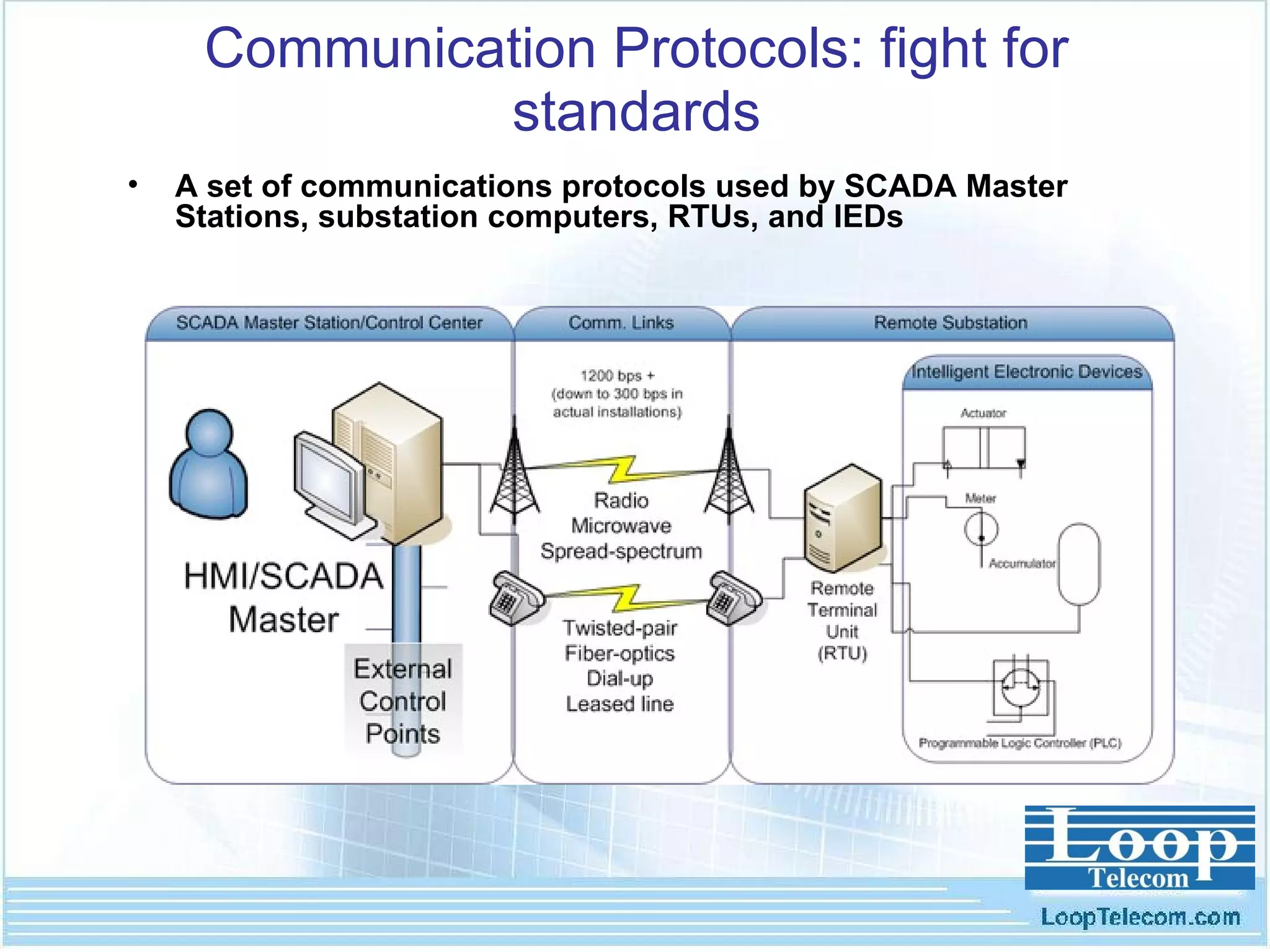
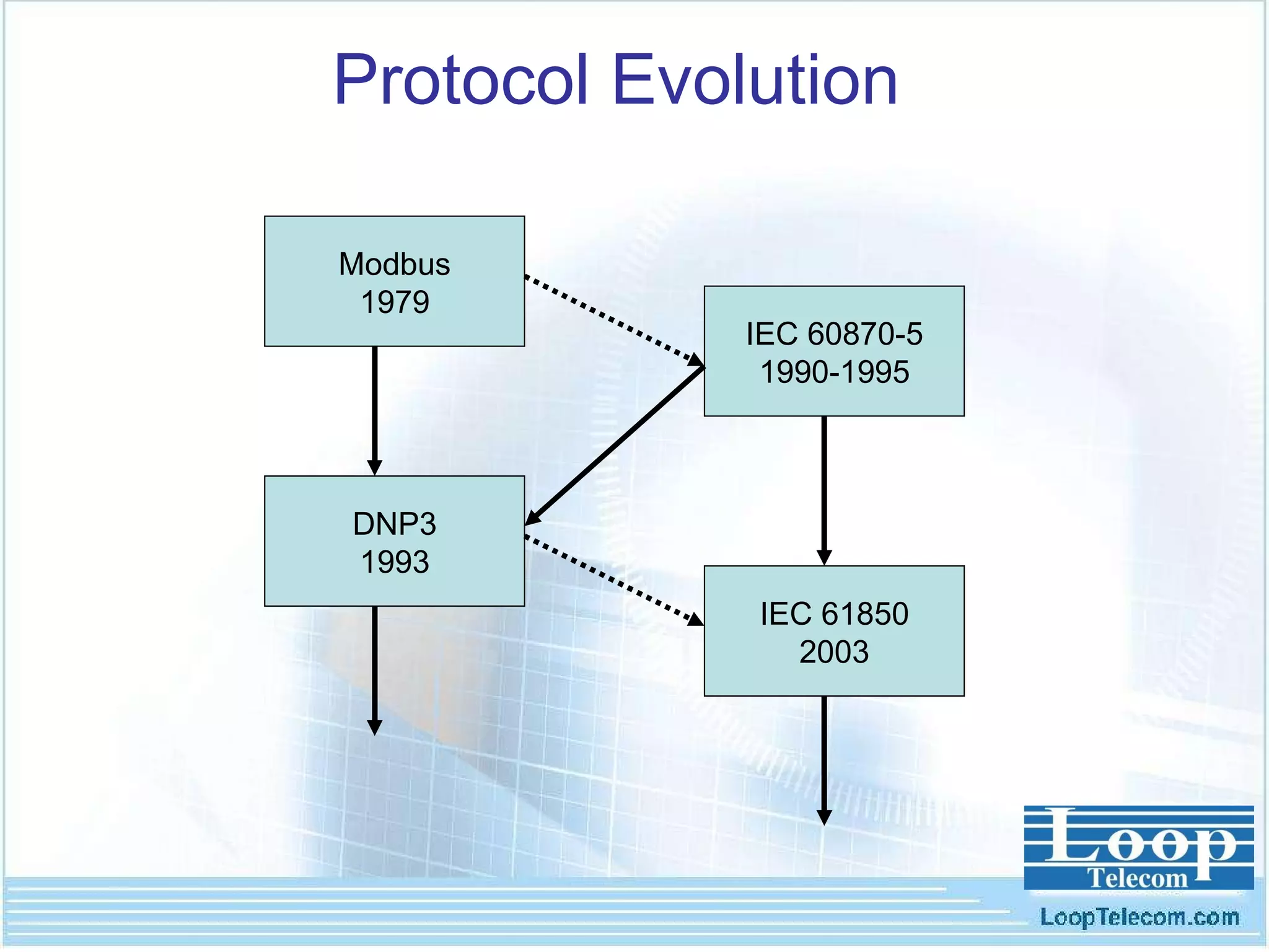
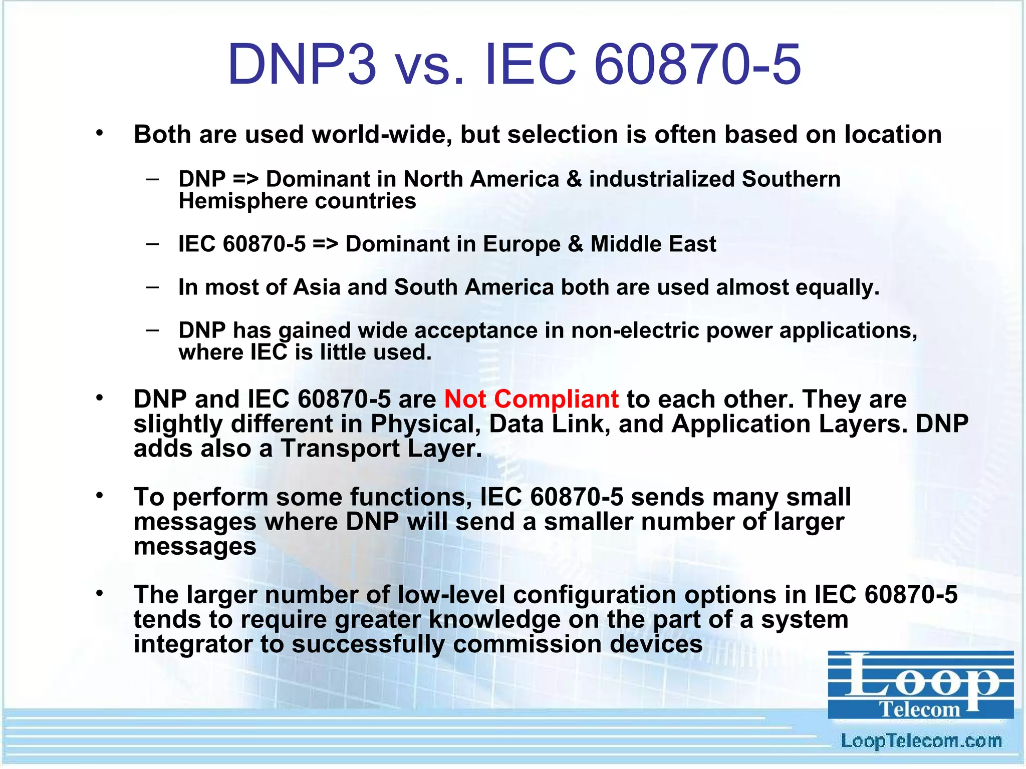
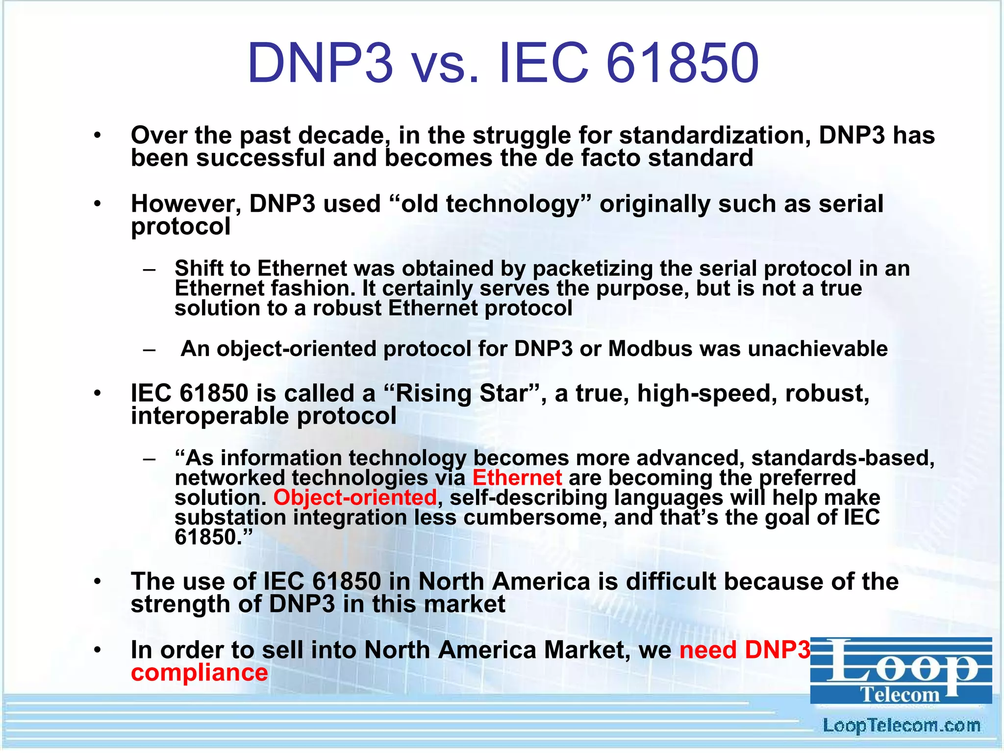
- The document discusses advanced communication networks for electric power applications, focusing on protocols like DNP3 and IEC 61850. It provides an overview of these protocols, their usage in different countries, and how IEC 61850 is emerging as an object-oriented, Ethernet-based standard.
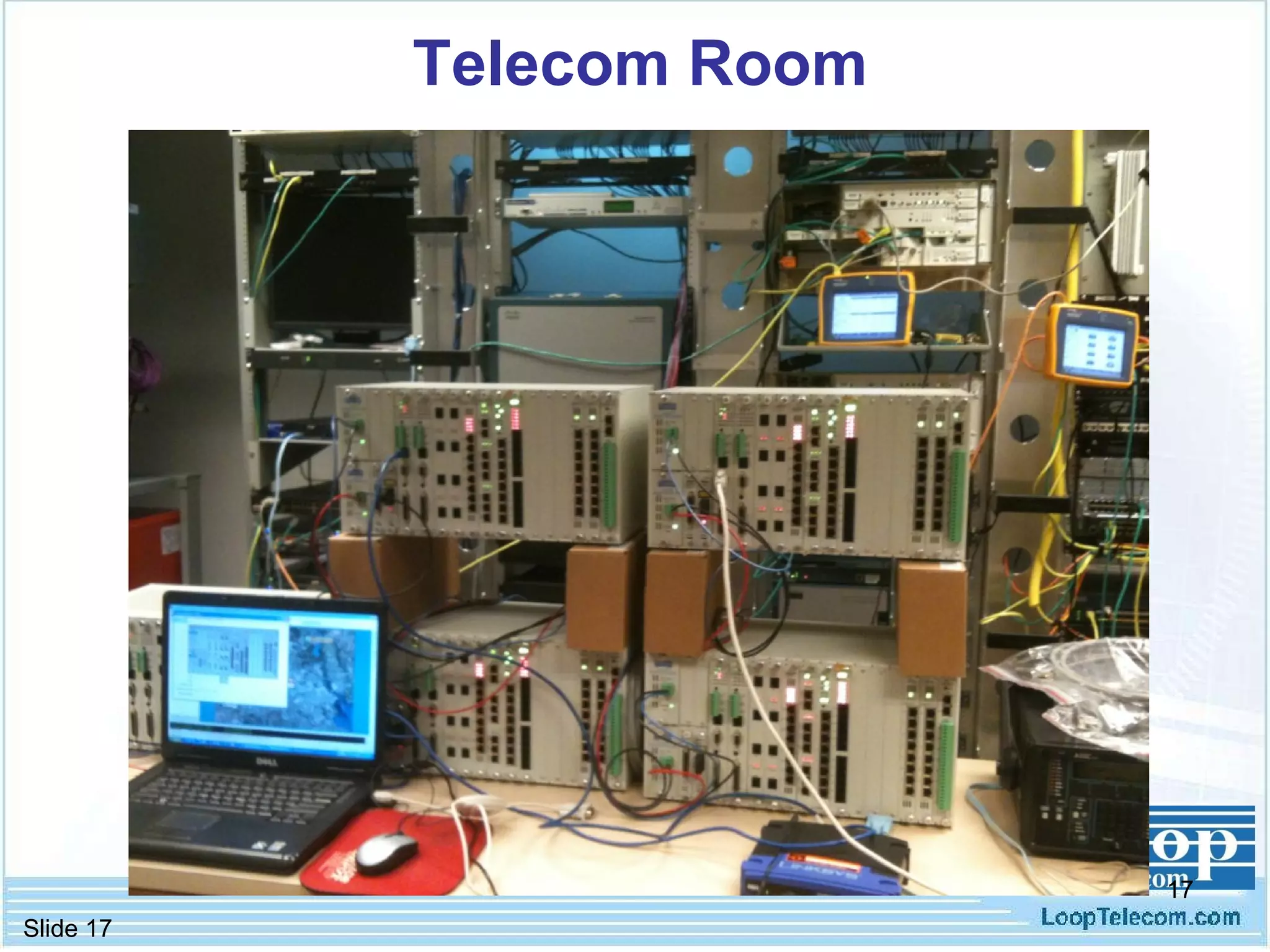
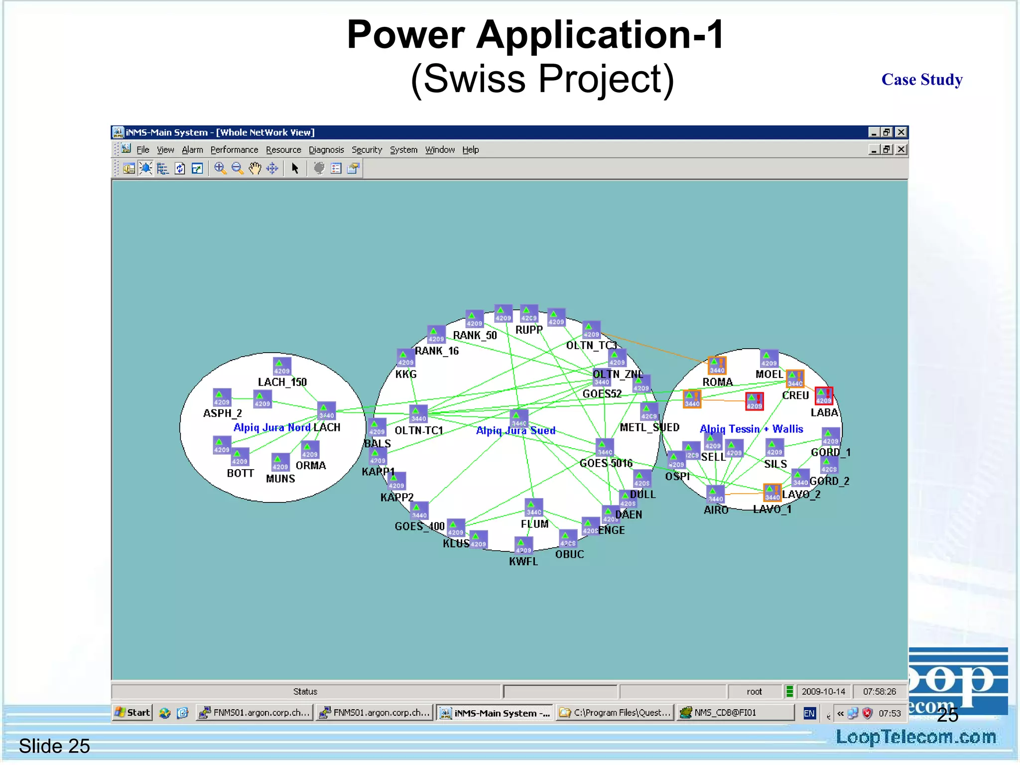
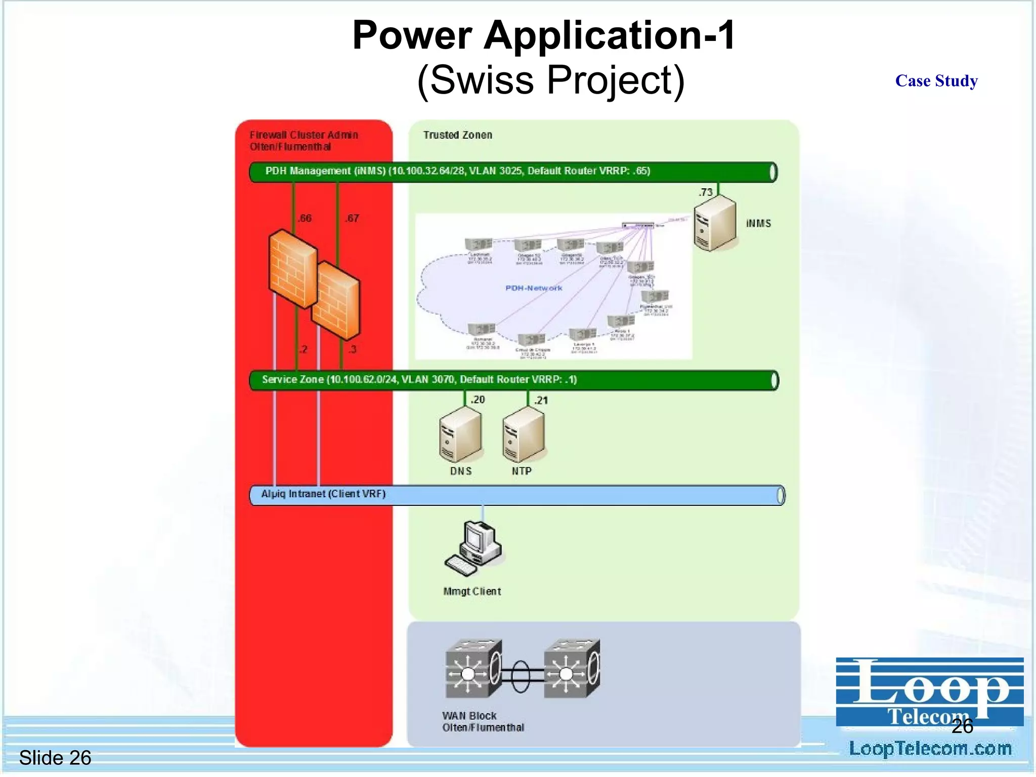
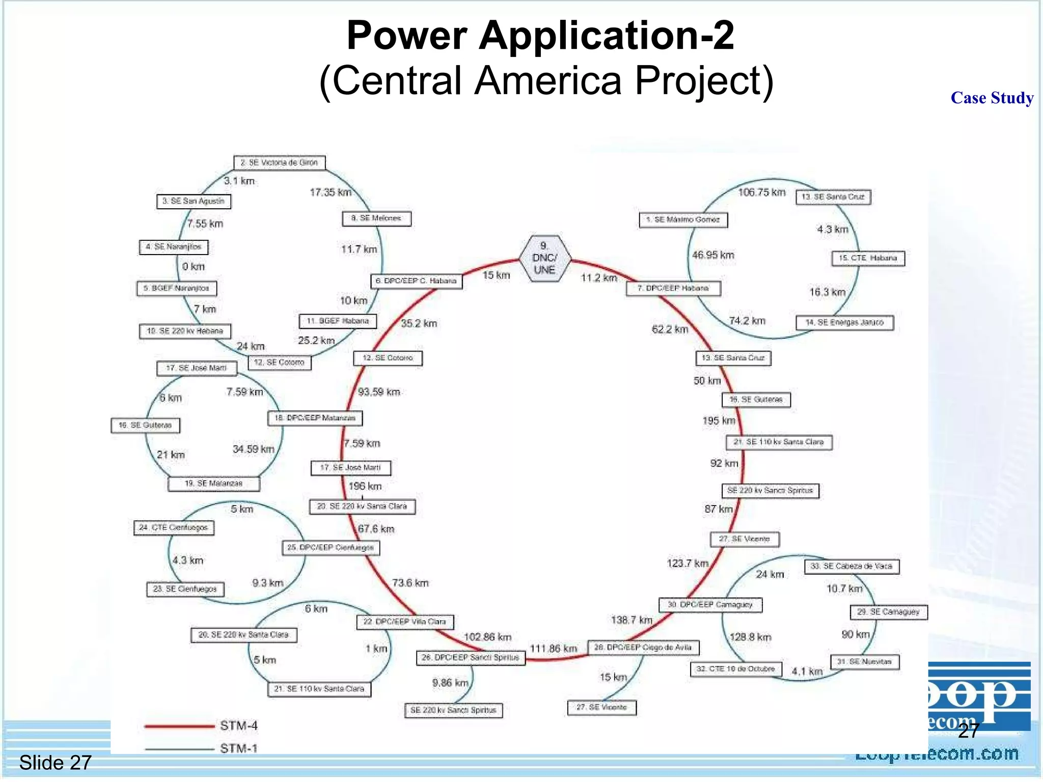
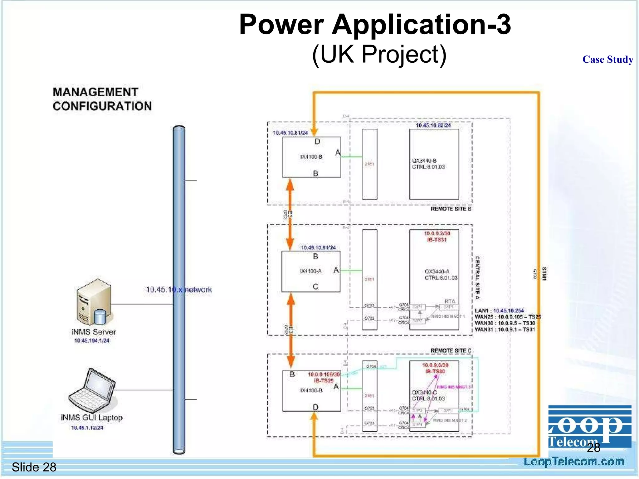
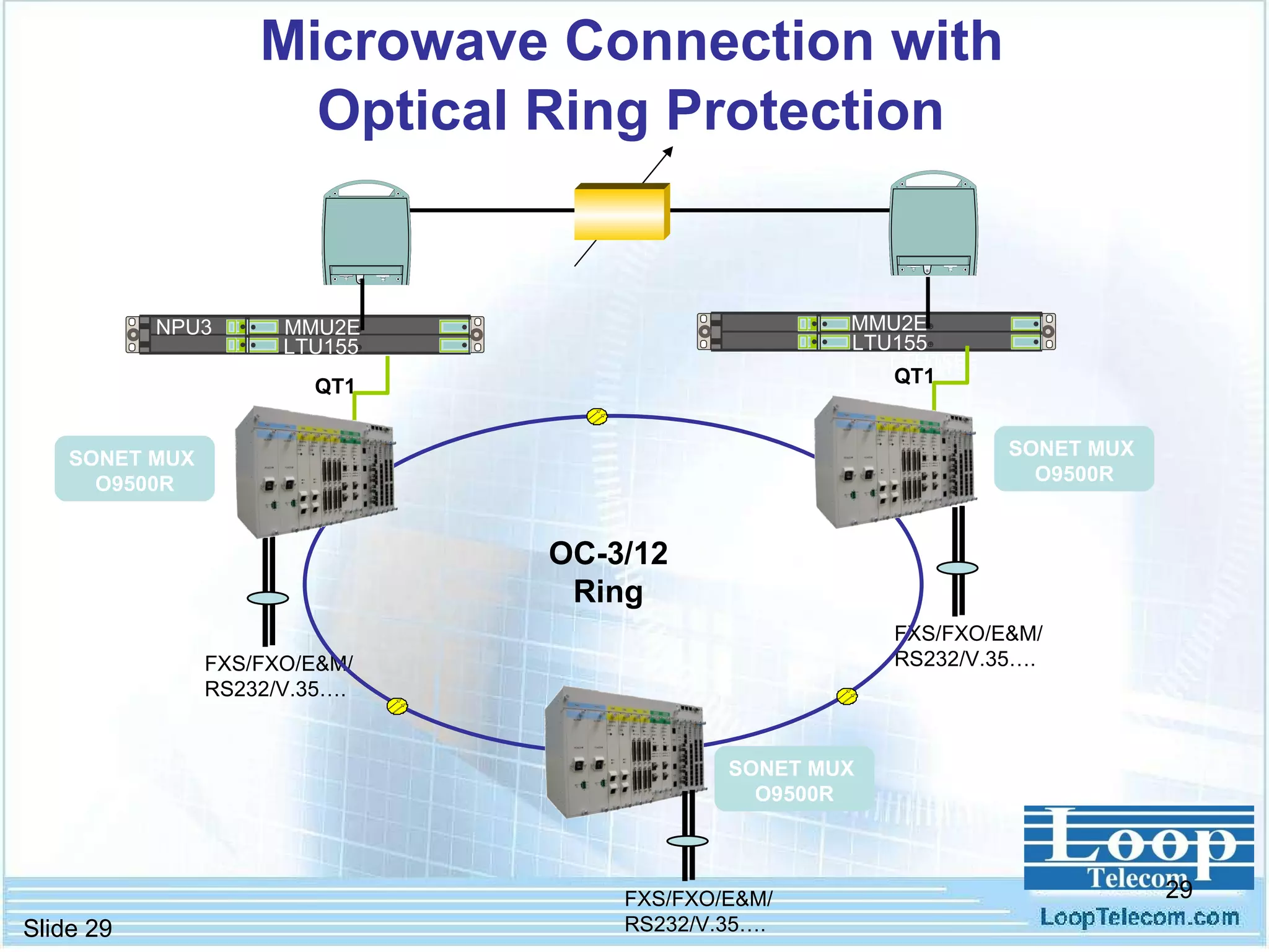
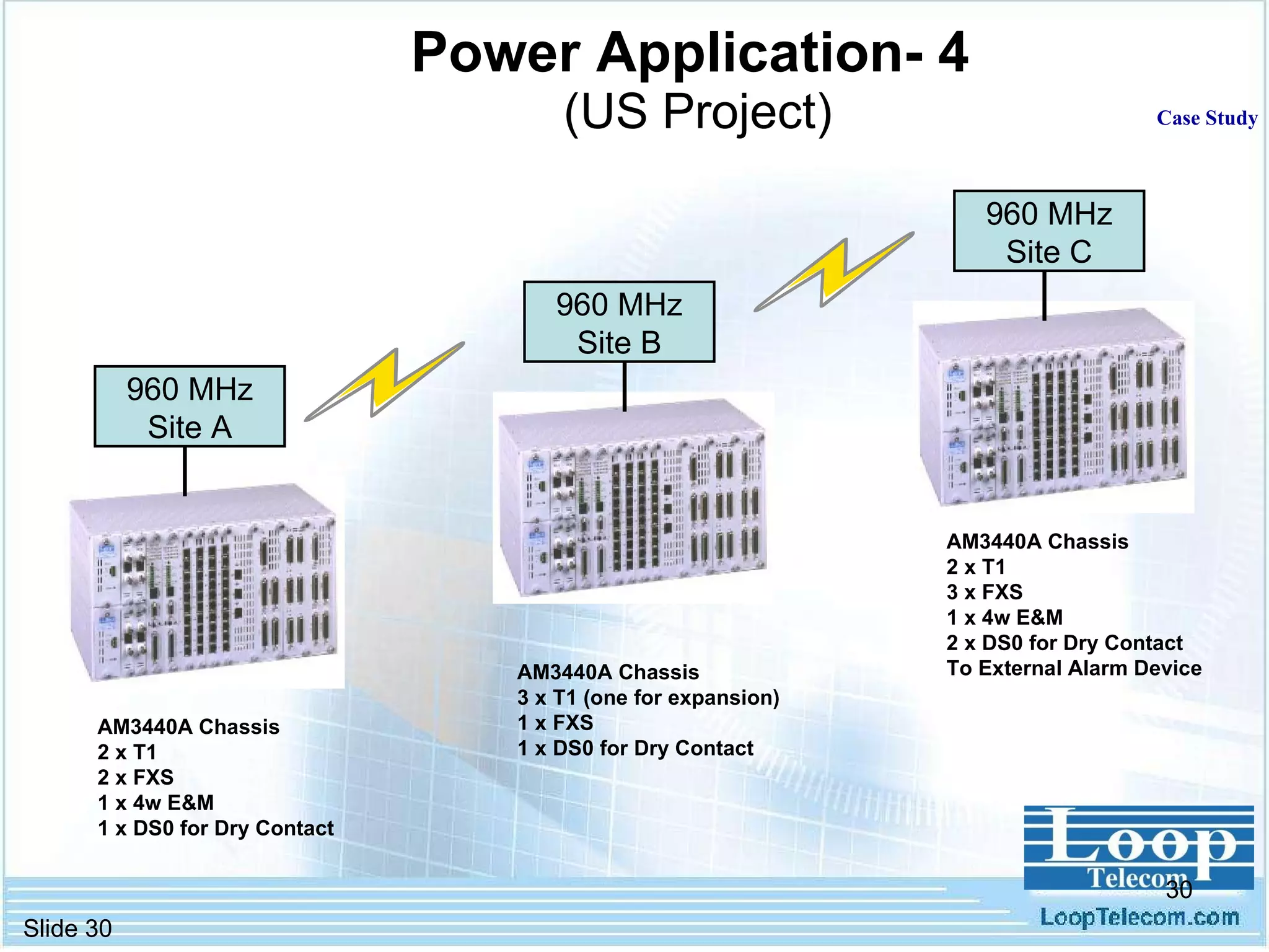
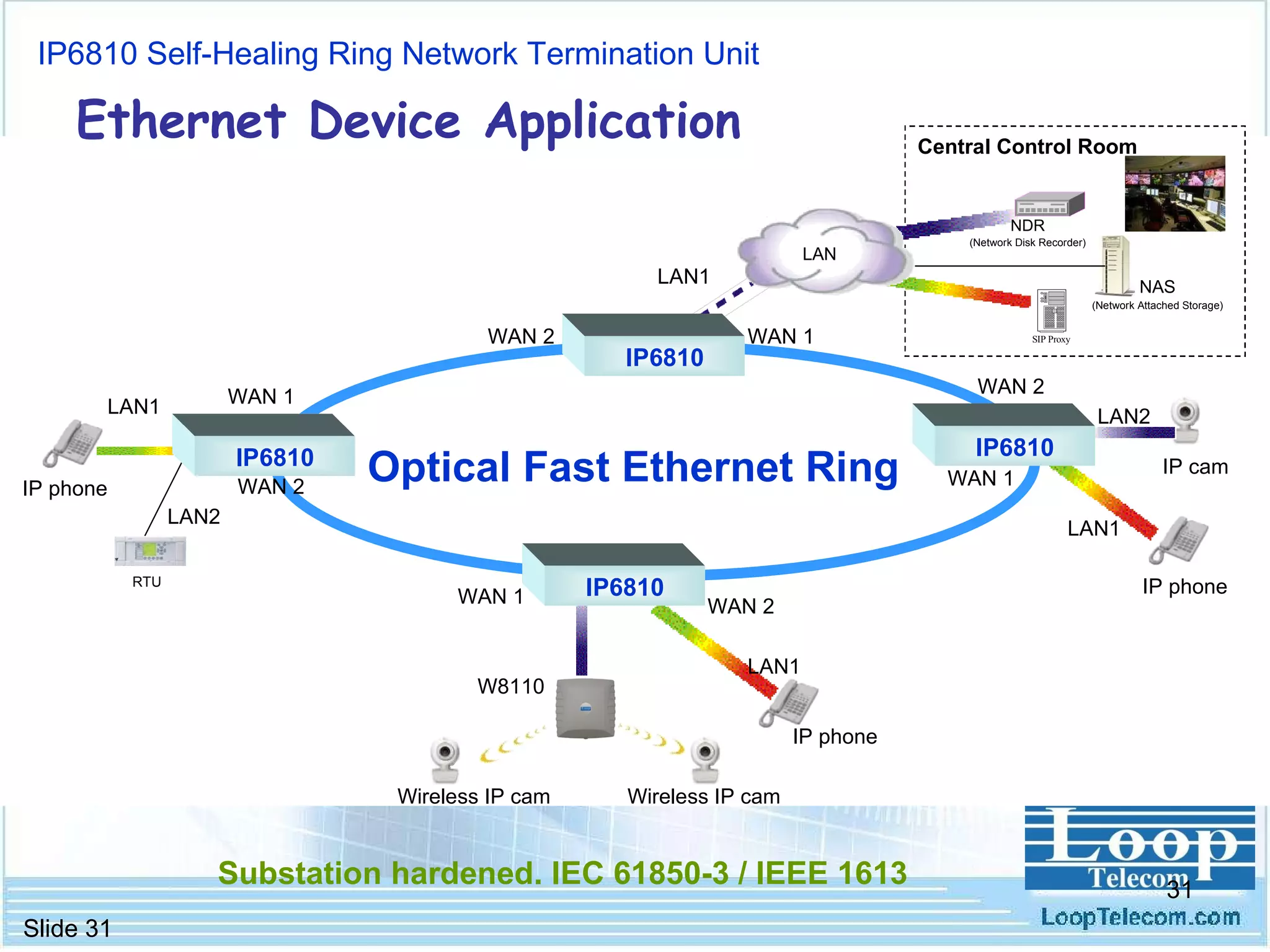
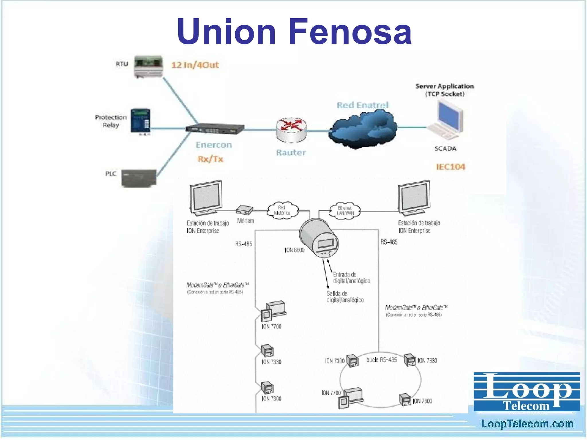
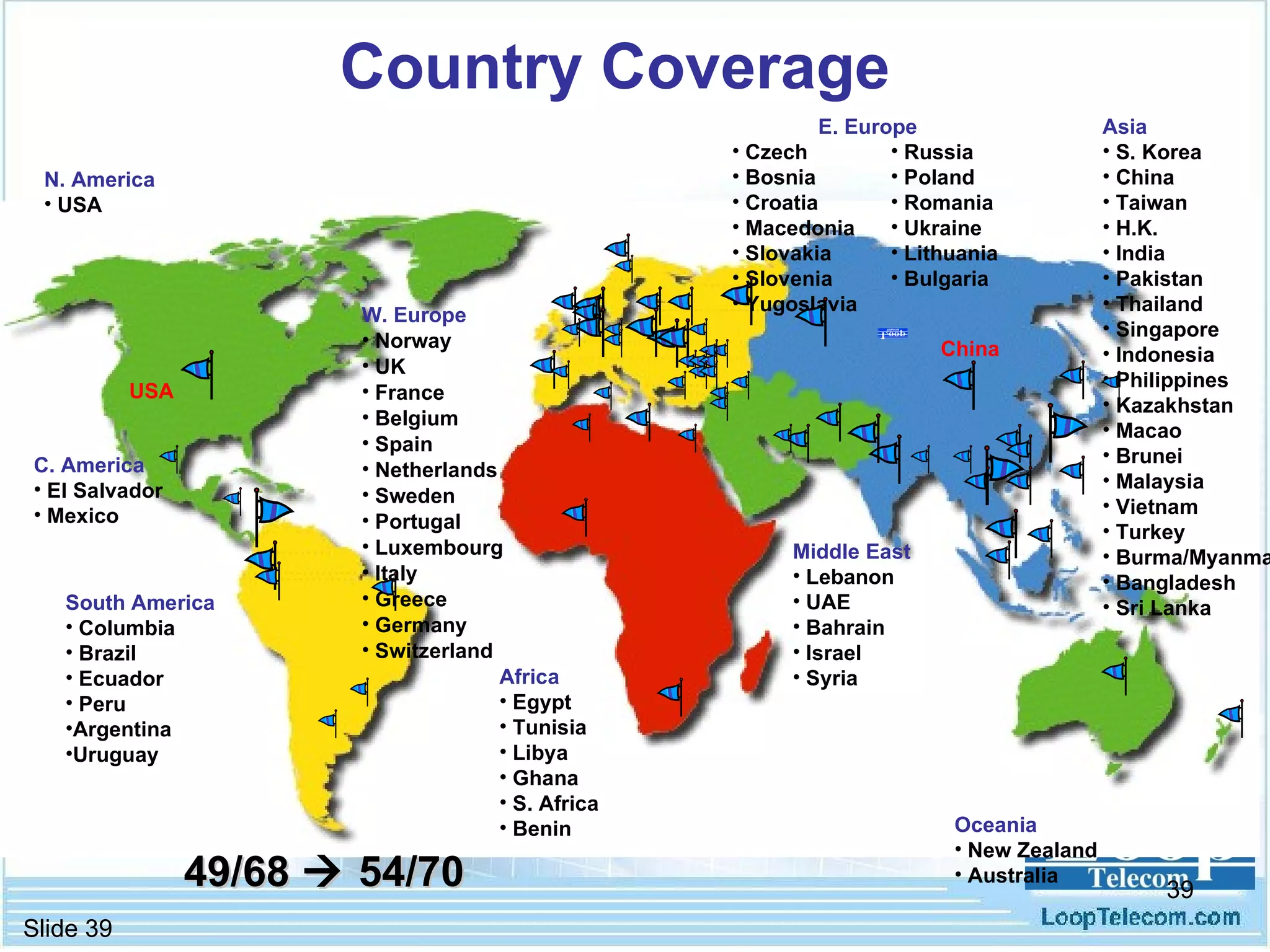
- Case studies are presented that demonstrate applications of Loop Telecom's solutions for various power utility communication networks around the world, including microwave, optical fiber, and wireless technologies.
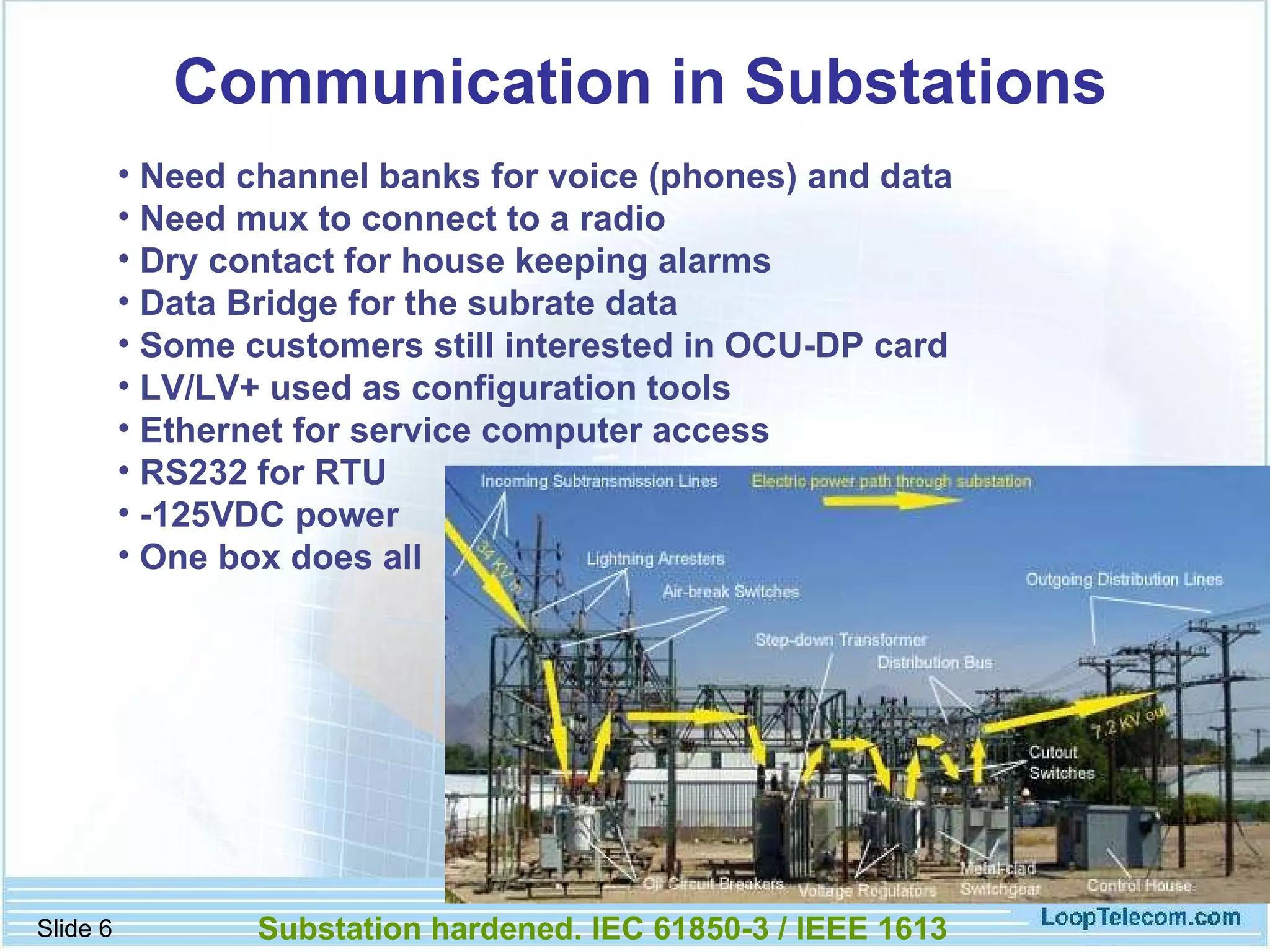
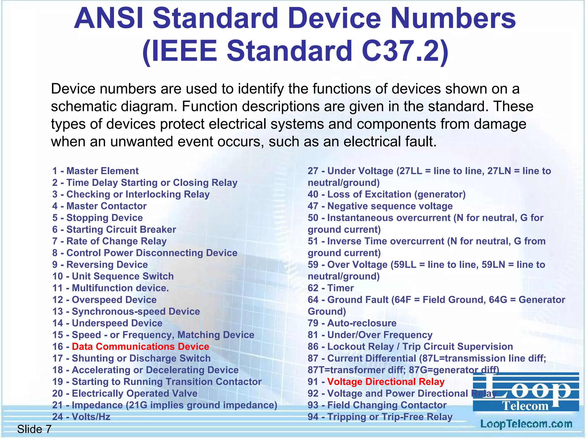
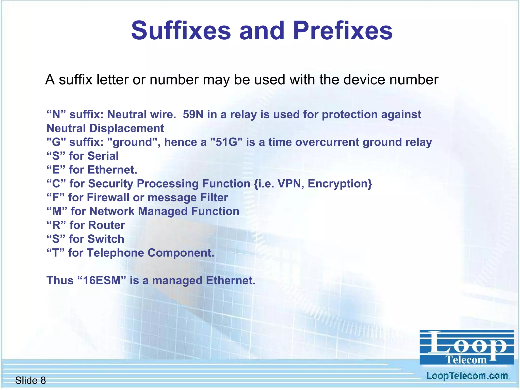
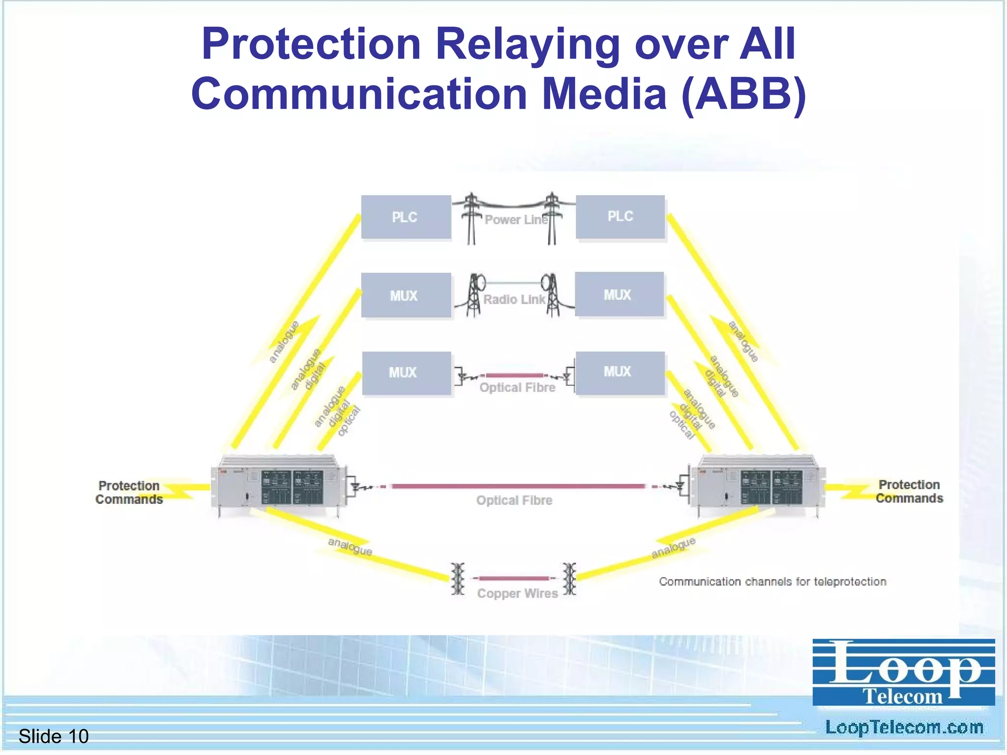
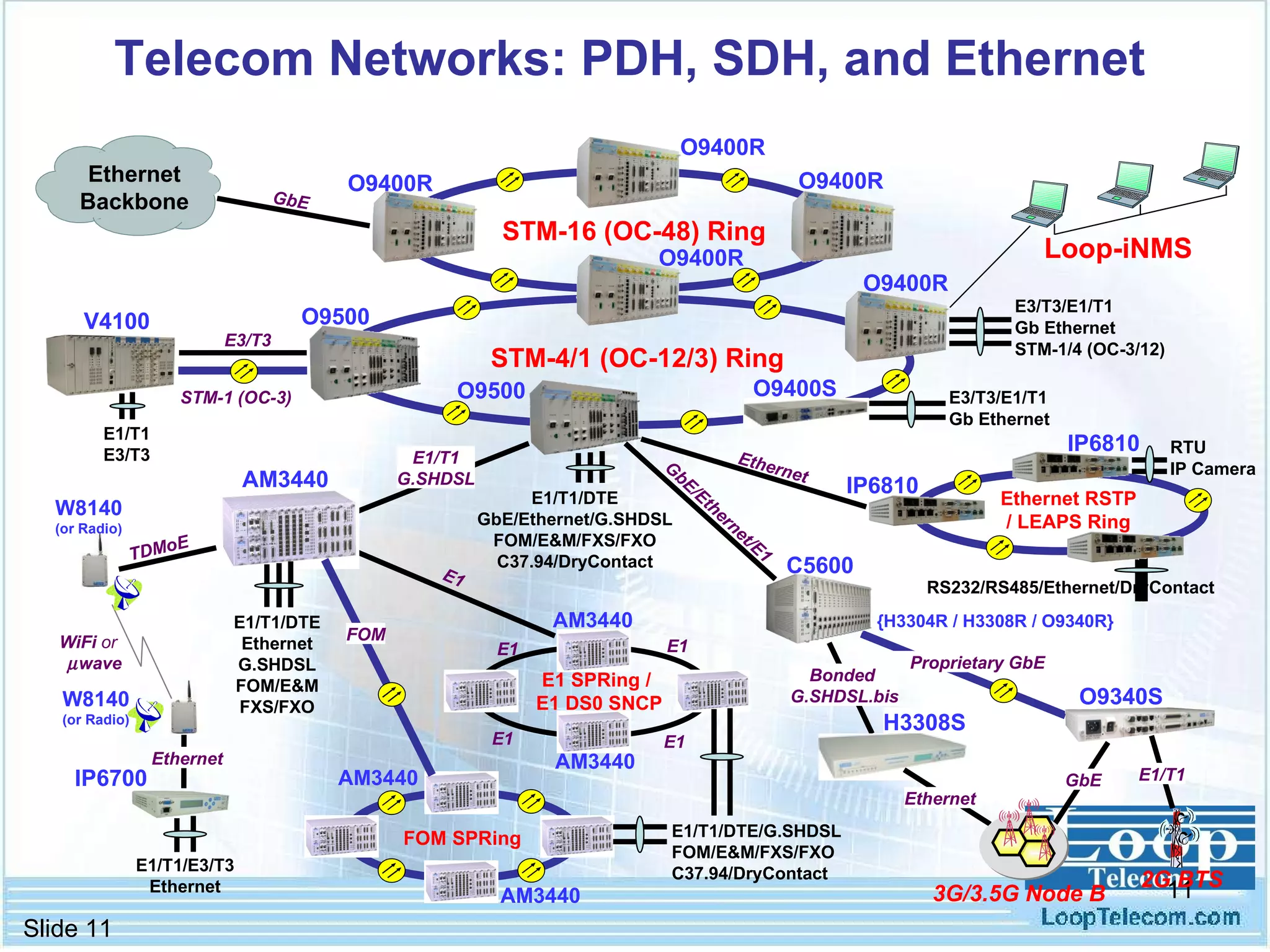
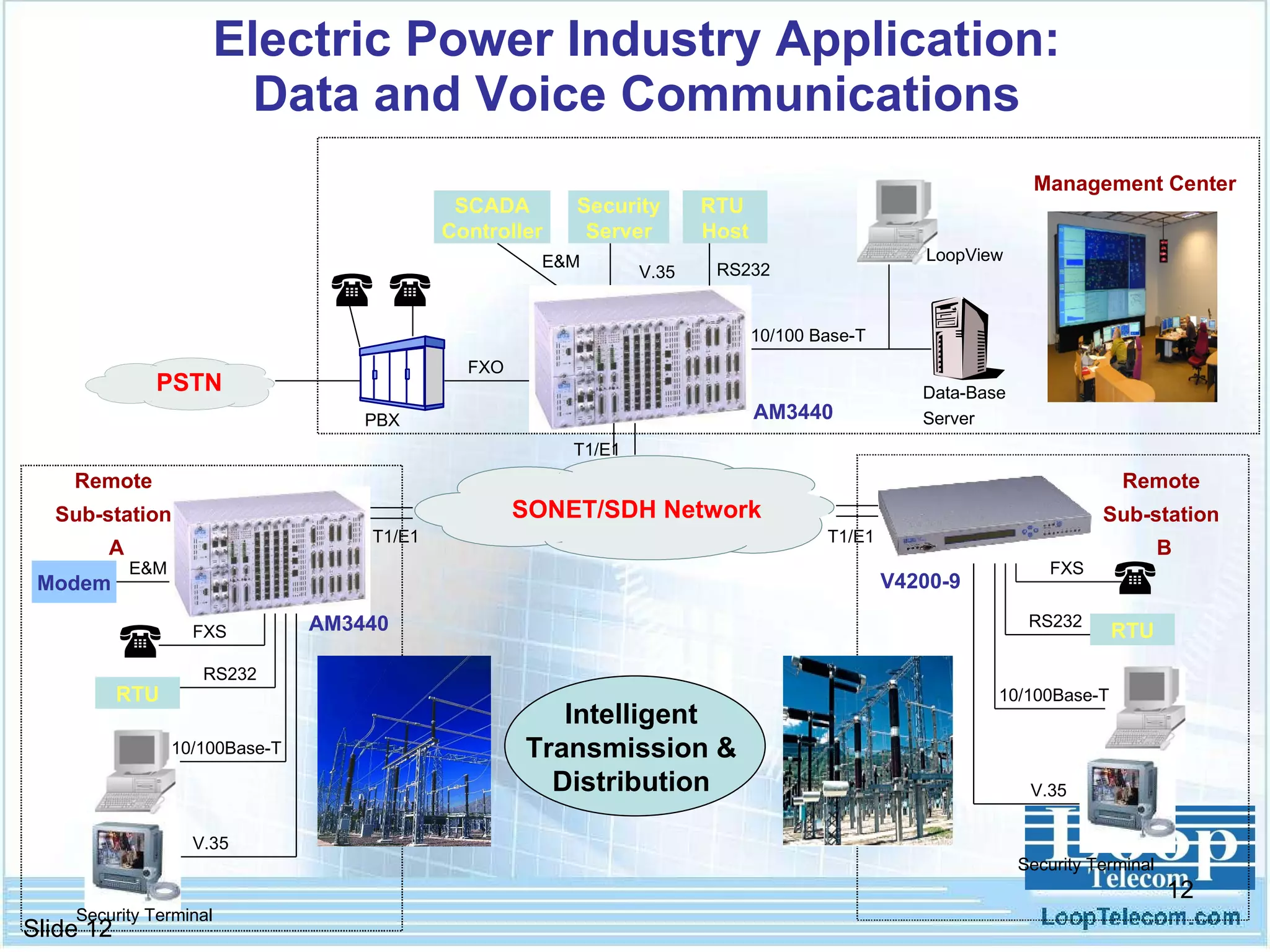
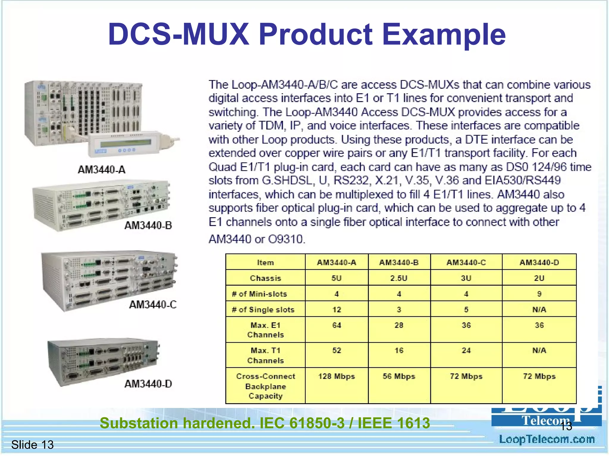
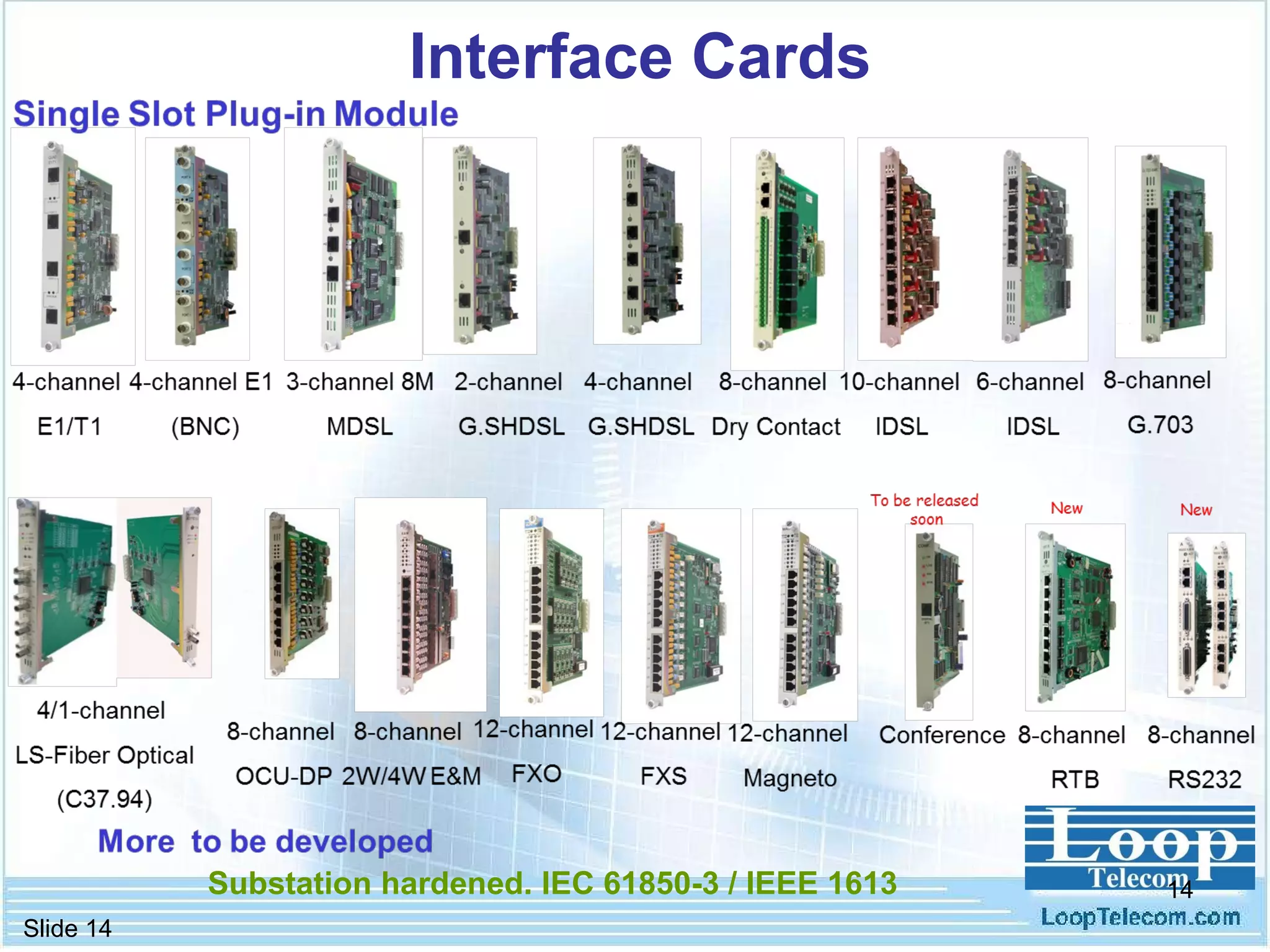
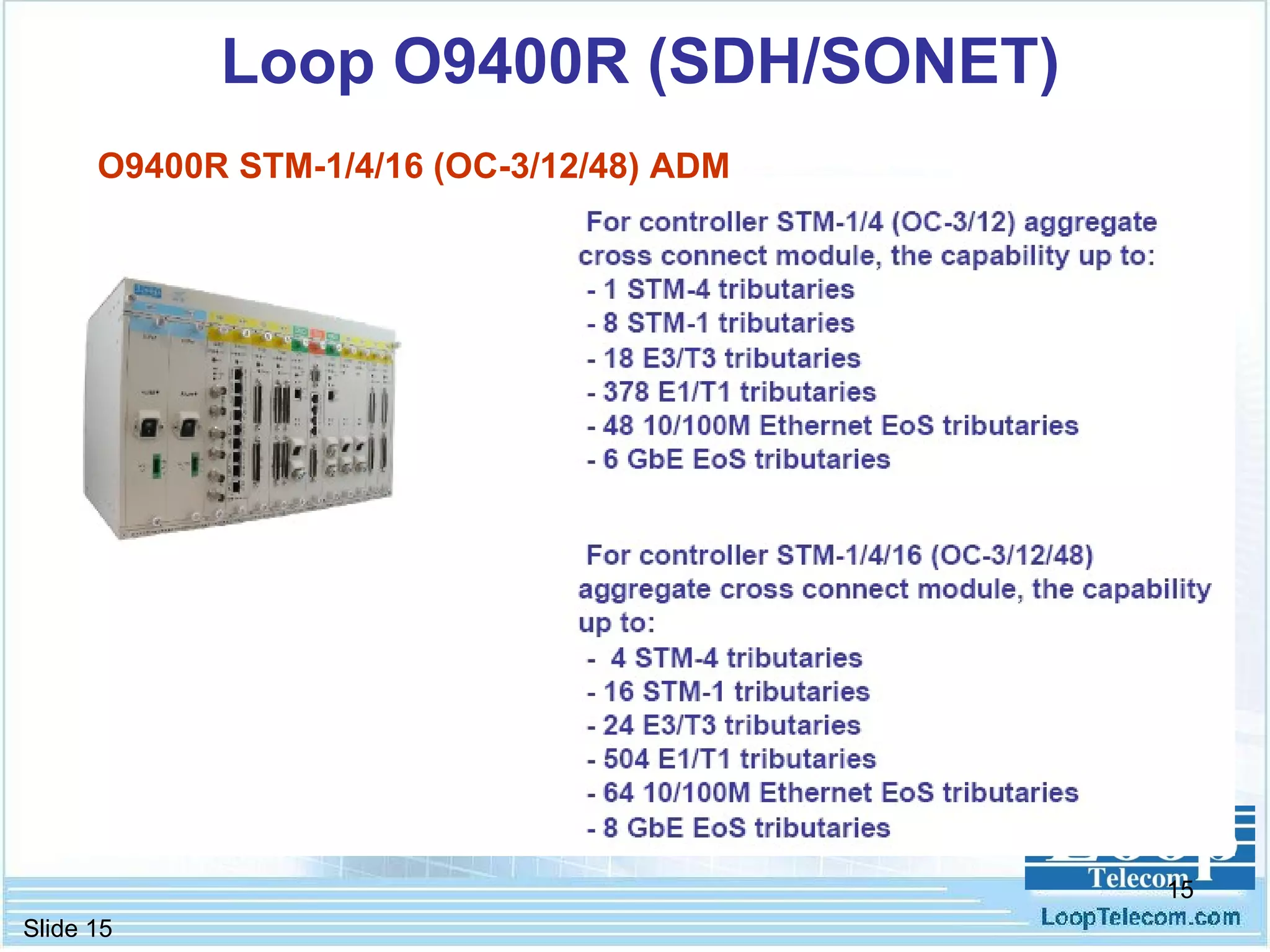
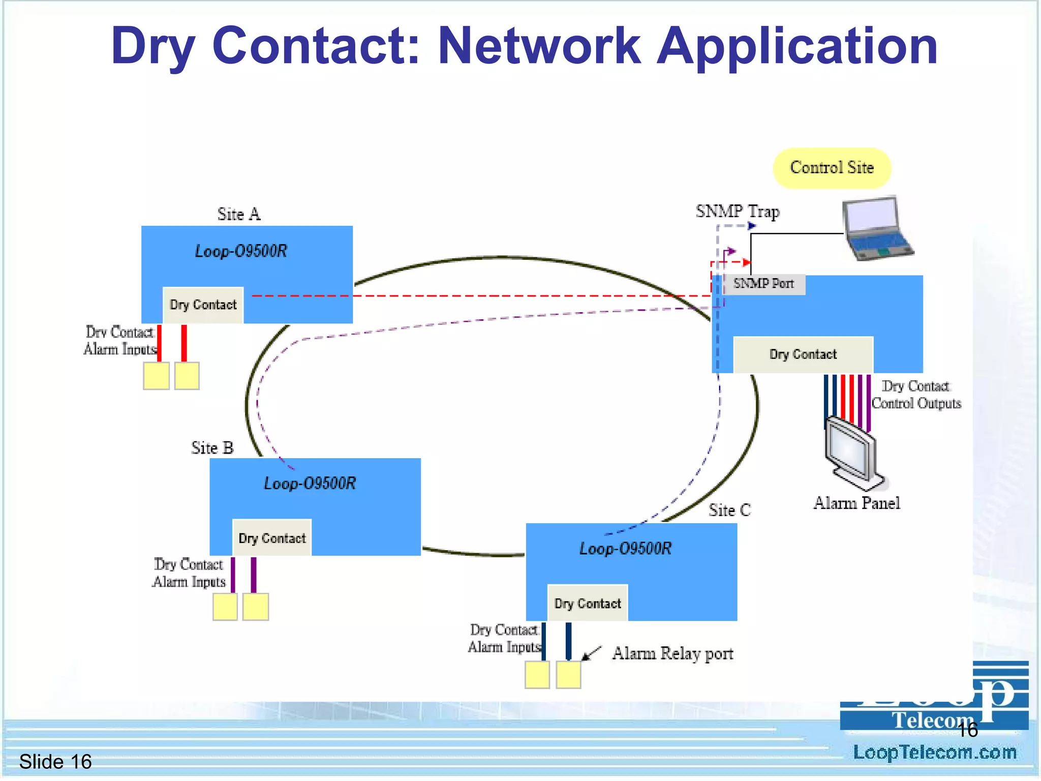
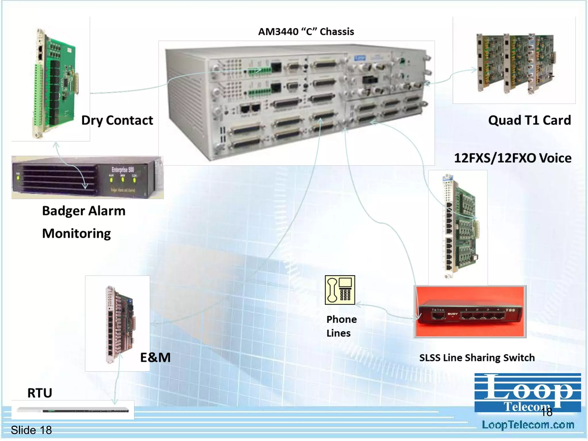
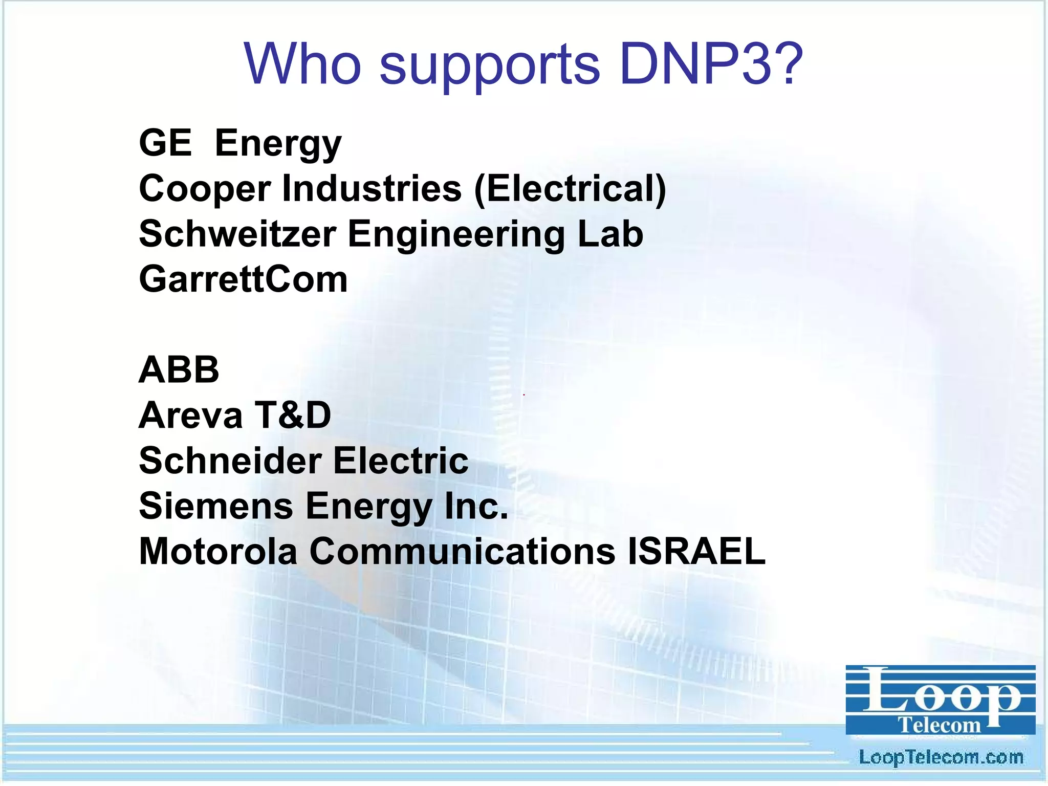
- Key components discussed include modems, multiplexers, routers, switches, and other devices that support protocols like DNP3, IEC 60870-5, and IEC 61850 over a variety of connection types.


![Thanks! George Wang Director – America Market Phone: +1.630.877.0031 (USA) [email_address] www.looptelecom.com](https://image.slidesharecdn.com/ieeenetsolu-13054006865445-phpapp01-110514142021-phpapp01/75/Advanced-Network-Solutions-for-Electric-Power-Application-40-2048.jpg)


![Circuit Network Analysis - [Chapter5] Transfer function, frequency response, ...](https://cdn.slidesharecdn.com/ss_thumbnails/ch5-150613063859-lva1-app6891-thumbnail.jpg?width=640&height=640&fit=bounds)
![Circuit Network Analysis - [Chapter4] Laplace Transform](https://cdn.slidesharecdn.com/ss_thumbnails/ch4-150613063858-lva1-app6891-thumbnail.jpg?width=640&height=640&fit=bounds)