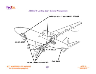
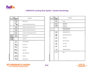
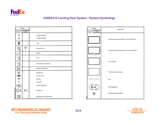
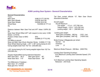
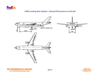
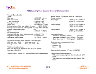
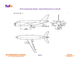
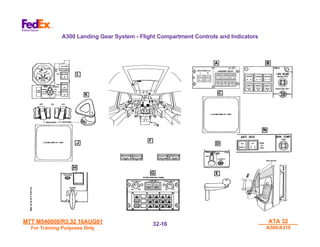
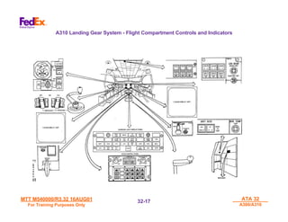
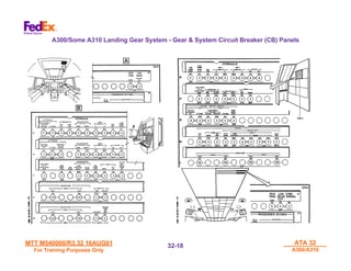
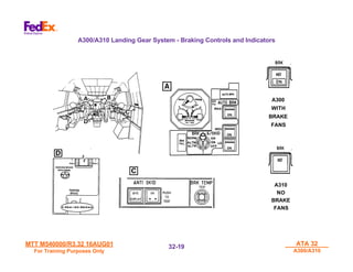
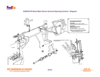
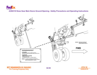
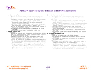
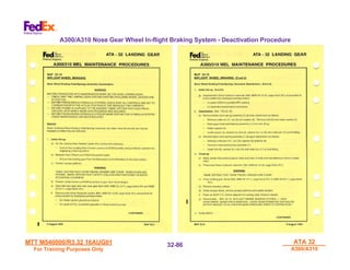
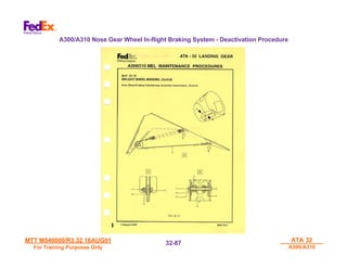
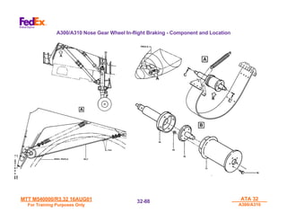
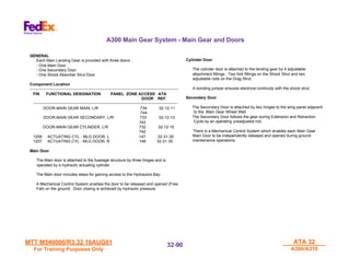
Airbus
Airbus
A300-600/A310-200
A300-600/A310-200
Airframe Systems
Airframe Systems
2
2
MTT M540000/R3.32 16AUG01
For Training Purposes Only
ATA 32
ATA 32
A300/A310
A300/A310
32-
32-2
2
Book 2 - Table of Contents
•
•ATA 32
ATA 32 Landing Gear
Landing Gear
•
•ATA 52
ATA 52 Doors
Doors
•
•ATA 36
ATA 36 Pneumatics
Pneumatics
•
•ATA 21
ATA 21 Air Conditioning
Air Conditioning
•
•ATA 30
ATA 30 Ice and Rain
Ice and Rain
•
•ATA 28
ATA 28 Fuel
Fuel
•
•ATA 26
ATA 26 Fire Protection
Fire Protection
Table of Contents
Table of Contents
MTT M540000/R3.32 16AUG01
For Training Purposes Only
ATA 32
ATA 32
A300/A310
A300/A310
32-
32-3
3
ATA 32
ATA 32
Landing Gear
Landing Gear
MTT M540000/R3.32 16AUG01
For Training Purposes Only
ATA 32
ATA 32
A300/A310
A300/A310
32-
32-4
4
THIS PAGE INTENTIONALLY
LEFT BLANK
MTT M540000/R3.32 16AUG01
For Training Purposes Only
ATA 32
ATA 32
A300/A310
A300/A310
32-
32-5
5
LANDING GEAR
LANDING GEAR
SYSTEM - GENERAL
SYSTEM - GENERAL
MTT M540000/R3.32 16AUG01
For Training Purposes Only
ATA 32
ATA 32
A300/A310
A300/A310
32-
32-6
6
The A300-600 is equipped with a tricycle type landing gear
with direct-action Shock Absorbers (Struts). The left and right
Main gears and the nose gear are retractable under hydraulic
power into wells closed off by gear doors.
The Main Gear, is installed under the wing and retracts
inboard, the gear structure being housed aft of the wing spar
box. Two doors, Mechanically linked to the gear structure
and following gear movement at all times, restore the wing
lower surface profile.
Each Bogie Beam Assembly, is returned to the "aligned"
position by a Pitch Damper Unit, is equipped with four Tire /
Wheel / Multidisc Brake Unit Assemblies. The Bogie Beam
Assemblies are housed in the mid-fuselage area commonly
called the Hydraulics Compartment (Bay) or Main Landing
Gear Wheel Well. The exterior fuselage profile is restored by
two Main Gear Doors each operated by a hydraulic actuating
cylinder.
The two Nose Gear Wheels are hydraulically steered on
the ground. The Nose Gear retracts forward into the
Nose Fuselage Section lower area and mechanically
actuates two Aft Doors which close off the aft part of the
Nose Gear Wheel Well. The forward part of the wheel
well is closed off by two Main Doors each operated by a
hydraulic actuating cylinder.
A Tail Gear protects the aft Fuselage Structure in the
event of excessive nose pitch-up or high nose landing
flare out conditions on the runway surface
Landing Gear - General
MTT M540000/R3.32 16AUG01
For Training Purposes Only
ATA 32
ATA 32
A300/A310
A300/A310
32-
32-7
7
A300/A310 Landing Gear - General Arrangement
MTT M540000/R3.32 16AUG01
For Training Purposes Only
ATA 32
ATA 32
A300/A310
A300/A310
32-
32-8
8
A300/A310 Landing Gear System - System Symbology
MTT M540000/R3.32 16AUG01
For Training Purposes Only
ATA 32
ATA 32
A300/A310
A300/A310
32-
32-9
9
A300/A310 Landing Gear System - System Symbology
MTT M540000/R3.32 16AUG01
For Training Purposes Only
ATA 32
ATA 32
A300/A310
A300/A310
32-
32-10
10
General Characteristics
Track :
Main Gear 9.6M (31 FT 5.95 IN)
Main Gear Wheels 0.927M (36.5 IN)
Nose Gear Wheels 0.625M (24.6 IN)
Wheel Base 18.603M (61 FT 0.4
IN)
Distance between Main Gear Fwd and AFT Axles:1.397M (55
IN)
Nose Gear Wheel Offset (AFT with respect to strut axis): 0.096
Meters (3.78 IN)
Position of Main Gear on MAC 50%
MAC 6.608M (21 FT 8.2 IN)
CG liMits on ground
Nose and Main Gear Shock Absorber Stroke: 0.450M (17.7 IN)
Nose Wheel Steering Angle: ± 65° / ± 95° during towing for A/C
having weights lower than 152 Ton (335,008 Lbs)
± 65° during towing for A/C having weights higher than 152 Ton
(335,008 Lbs)
Angular displaceMent during extension/retraction
Main Gear Strut : 80.3° Main gear Doors : 90°
Nose Gear Strut : 110° Nose Gear Doors : 88°
Tire DiMensions (Tubeless) :
Main Gear 47 x 18-R20
Nose gear 40 x 14-R16
Tail Gear contact attitude: 12°, Main Gear Shock
Absorbers Extended
Aircraft weight :
Aircraft Maximum
Taxi weight : 171.4 t (377,766 Lbs)
Takeoff weight : 170.5 t (375,782 Lbs)
Landing weight : 140 t (308,560 Lbs)
Landing gear weight :
Nose gear (complete) : 690 Kg (1521 Lbs)
Main gear (complete) : 6467 Kg (14253 Lbs)
Brake Energy in Megajoules per wheel :
Normal : 34
Overload :
Limit : 77
Maximum Brake Pressure : 206 Bars (3000 PSI)
Landing Gear Operating Envelope :
VLE (Maximum Landing Gear Extended Speed): 270
Knots
VLO (Maximum Landing Gear Operating Speed)
Retraction : 240 Knots
A300 Landing Gear System - General Characteristics
MTT M540000/R3.32 16AUG01
For Training Purposes Only
ATA 32
ATA 32
A300/A310
A300/A310
32-
32-11
11
A300 Landing Gear System - General Dimensions on Aircraft
MTT M540000/R3.32 16AUG01
For Training Purposes Only
ATA 32
ATA 32
A300/A310
A300/A310
32-
32-12
12
General Characteristics
Track :
Main gear 9.6M (31 FT. 5.95 IN)
Main gear wheels 0.927M (36.5 IN)
with provision for 0.978M (38.5 IN)
Nose gear wheels 0.625M (24.6 IN)
Wheel base 18.603M (61 FT. 0.4 IN)
Distance between Main gear fwd and aft axles 1.397M (55 IN)
Nose gear wheel offset (aft with respect to leg axis)0.096M (3.78 IN)
Position of Main gear on MAC 50%
MAC 6.608M (21 FT. 8.2 IN)
CG limits on ground
Nose and Main gear shock absorber stroke 0.450M (17.7 IN)
Bogie beam in-flight position 10.3° pitch-down
Nose wheel steering angle ± 65° / ± 95° ( towing)
Angular displacement during extension / retraction cycle
Main gear strut : 80.3° Main gear doors : 89°
Nose gear strut : 110° Nose gear doors : 88°
Tire dimensions (tubeless) :
Main gear 46 x 16-20 (49 x 17-20 and 19-20 / as options)
Nose gear 40 x 14-16
Tail gear contact attitude : 12°, Main gear shock absorbers extended
Aircraft Weight: A310 aircraft varies per Tail Number
Aircraft maximum
Taxi weight : 125,900 kg (277,500 lbs) to
142,900 kg (315,000 lbs)
Takeoff weight : 125,000 kg (275,600 lbs) to
142,000 kg (313,100 lbs)
Landing weight : 118,500 kg (261,200 lbs) to
121,500 kg (267,900 lbs)
Landing gear weight :
Nose Gear (complete) : 690 kg (1521 lbs)
Main Gear (complete) : 2710 kg each (5974 lbs)
Bogie Beam Assy : 1510 kg each (3329 lbs)
Brake energy in megajoules per wheel :
Normal : 26
Overload : 33
Limit : 62
Maximum brake pressure : 175 bars (2538 PSI)
Landing gear operating envelope :
VLO (Maximum Landing Gear Operating Speed) : 270
Knots
VLE (Maximum Landing Gear Extended Speed) : 240
Knots
A310 Landing Gear System - General Characteristics
MTT M540000/R3.32 16AUG01
For Training Purposes Only
ATA 32
ATA 32
A300/A310
A300/A310
32-
32-13
13
A310 Landing Gear System - General Dimensions on Aircraft
MTT M540000/R3.32 16AUG01
For Training Purposes Only
ATA 32
ATA 32
A300/A310
A300/A310
32-
32-14
14
THIS PAGE INTENTIONALLY
LEFT BLANK
MTT M540000/R3.32 16AUG01
For Training Purposes Only
ATA 32
ATA 32
A300/A310
A300/A310
32-
32-15
15
LANDING GEAR
LANDING GEAR
CONTROLS AND
CONTROLS AND
INDICATIONS
INDICATIONS
MTT M540000/R3.32 16AUG01
For Training Purposes Only
ATA 32
ATA 32
A300/A310
A300/A310
32-
32-16
16
A300 Landing Gear System - Flight Compartment Controls and Indicators
MTT M540000/R3.32 16AUG01
For Training Purposes Only
ATA 32
ATA 32
A300/A310
A300/A310
32-
32-17
17
A310 Landing Gear System - Flight Compartment Controls and Indicators
MTT M540000/R3.32 16AUG01
For Training Purposes Only
ATA 32
ATA 32
A300/A310
A300/A310
32-
32-18
18
A300/Some A310 Landing Gear System - Gear & System Circuit Breaker (CB) Panels
MTT M540000/R3.32 16AUG01
For Training Purposes Only
ATA 32
ATA 32
A300/A310
A300/A310
32-
32-19
19
A300/A310 Landing Gear System - Braking Controls and Indicators
A300
WITH
BRAKE
FANS
A310
NO
BRAKE
FANS
MTT M540000/R3.32 16AUG01
For Training Purposes Only
ATA 32
ATA 32
A300/A310
A300/A310
32-
32-20
20
NOTE
Some A300 / A310 aircraft have visual indicators removed
due to binding and broken parts. Mechanical Indication
System components removed per Engineering Order on an
Attrition Basis.
MECHANICAL INDICATOR PINS
A red Indicator Pin appears on each Wing Upper
Surface (above the Main Gear Shock Absorber
Strut Well area) when the associated Main Gear
is down and locked.
The Indicator Pins are not visible from the Main
Deck Cargo Compartment area due to the Cargo
Freighter Configuration.
A300/A310 Landing Gear System - Visual Downlock Indication - Main Gear
MTT M540000/R3.32 16AUG01
For Training Purposes Only
ATA 32
ATA 32
A300/A310
A300/A310
32-
32-21
21
LANDING GEAR HANDCRANK
A stop is provided after approximately 20 turns to extend the landing
gear free-fall (gravity method). To restore to normal condition,
reverse procedure till return stop is touched by emergency extension
mechanism under flight deck floor.
Stowed in F/O console for free fall extension the handle must be
inserted in a protected flight compartment floor fitting aft of the center
pedestal on RH side, then rotated clockwise.
Green hydraulic pressure is first isolated then, all chambers are
connected to the green reservoir. At 17.5 turns, doors unlock. At 19.5
turns gears unlock, free fall and downlock assisted by aerodynamic
forces (nose L/G) and spring assistance (Main L/G). Doors will
remain opened until flight or ground reconditioning.
LANDING GEAR HANDCRANK FITTING
A300/A310 Landing Gear System - Emergency Extension (Gravity Method) - Location and Hand
Crank Assembly
MTT M540000/R3.32 16AUG01
For Training Purposes Only
ATA 32
ATA 32
A300/A310
A300/A310
32-
32-22
22
THIS PAGE INTENTIONALLY
LEFT BLANK
MTT M540000/R3.32 16AUG01
For Training Purposes Only
ATA 32
ATA 32
A300/A310
A300/A310
32-
32-23
23
LANDING GEAR
LANDING GEAR
HYDRAULIC AND
HYDRAULIC AND
ELECTRICAL POWER
ELECTRICAL POWER
SOURCES
SOURCES
MTT M540000/R3.32 16AUG01
For Training Purposes Only
ATA 32
ATA 32
A300/A310
A300/A310
32-
32-24
24
P
NORMAL BRAKE
LANDING GEAR
NW STEERING
ALTN BRAKE
PARK BRAKE
YELLOW
RESERVIOR
GREEN
RESERVIOR
BLUE
RESERVIOR
A300/A310 Landing Gear System - Hydraulic Power Supply
MTT M540000/R3.32 16AUG01
For Training Purposes Only
ATA 32
ATA 32
A300/A310
A300/A310
32-
32-25
25
NOSE WHEEL STEERING
LDG GEAR EXTENTION/RETRACTION
NORMAL
BRAKING
ALTERNATE
BRAKING + PARKING BRAKE
AUTOMATIC
SELECTOR
M
P
GREEN
HP MANIFOLD
YELLOW
HP
MANIFOLD
M
A300/A310 Landing Gear System - Hydraulic Power Users
MTT M540000/R3.32 16AUG01
For Training Purposes Only
ATA 32
ATA 32
A300/A310
A300/A310
32-
32-26
26
A300 Landing Gear System - Landing Gear Electrical Power Supply
MTT M540000/R3.32 16AUG01
For Training Purposes Only
ATA 32
ATA 32
A300/A310
A300/A310
32-
32-27
27
A310 Landing Gear System - Landing Gear Electrical Power Supply
MTT M540000/R3.32 16AUG01
For Training Purposes Only
ATA 32
ATA 32
A300/A310
A300/A310
32-
32-28
28
THIS PAGE INTENTIONALLY
LEFT BLANK
MTT M540000/R3.32 16AUG01
For Training Purposes Only
ATA 32
ATA 32
A300/A310
A300/A310
32-
32-29
29
NOSE GEAR ASSEMBLY
NOSE GEAR ASSEMBLY
COMPONENTS AND
COMPONENTS AND
SAFETY DEVICES
SAFETY DEVICES
MTT M540000/R3.32 16AUG01
For Training Purposes Only
ATA 32
ATA 32
A300/A310
A300/A310
32-
32-30
30
GENERAL
The nose gear is hinged on the structure between frames 16A and 17.
The nose gear includes a hydraulic actuating cylinder, a telescopic drag strut, direct acting shock absorber and a system for steering the nose
wheels on the ground.
Five doors close off the nose gear well and restore the fuselage profile.
It is extended and retracted by the Green Hydraulic System Gear Actuating Cylinder.
The Nose Gear is equipped with an Oleo Type Shock Absorber. The Link Tube supports the Trunnion, allowing the gear to be hinged between
Fuselage Frame (FR) 16A and 17.
The shock Absorber Rotating Barrel controlled by the Nose Wheel Steering (NWS) is linked to the Shock Absorber by a Torque Link Assembly.
The Nose Gear Telescope Drag Strut provides fore and aft bracing of the Nose Gear in the down locked position.
Mechanical locking of the drag strut is achieved by internal locking dogs. The internal locking dogs are released during landing gear retraction
cycle (Nose Gear Retraction Phase).
A300/A310 Nose Landing Gear System - General Description
MTT M540000/R3.32 16AUG01
For Training Purposes Only
ATA 32
ATA 32
A300/A310
A300/A310
32-
32-31
31
A300/A310 Nose Landing Gear System - General Features
MTT M540000/R3.32 16AUG01
For Training Purposes Only
ATA 32
ATA 32
A300/A310
A300/A310
32-
32-32
32
A locking mechanism using a safety pin secures the landing
gear on the ground and prevents accidental nose gear
retraction during static and pressurized conditions.
NOSE GEAR TELESCOPIC STRUT
The nose gear telescopic drag strut provides nose gear
downlocking and bracing in the fore and aft position.
Mechanical locking of the drag strut is achieved by internal
locking dogs.
Downlock release is achieved hydraulically by action on a
locking sleeve which frees the locking dogs.
During gear extension the locking sleeve is repositioned
hydraulically. At the end of the rod extension a microswitch
indicates that the drag strut is downlocked. A visual indicator
(mechanical) also appears when the strut is downlocked.
A mechanical system is provided for immobilizing the locking
sleeve on the ground by insertion of a safety pin. During this
operation and especially after a landing gear Free Fall
extension with the aircraft on jacks it is highly important to
make certain that the drag strut is positively downlocked as
installation of the safety pin is possible when the strut is not
downlocked.
NOSE WHEEL STEERING
WARNING: WHENEVER THE GROUND SAFETY PIN IS
INSTALLED ON THE NOSE GEAR TELESCOPIC STRUT,
ALWAYS VISUALLY CHECK THAT:
• IT HAS COMPLETELY AND EASILY ROTATED THE
FORK-TYPE LEVER OF THE GROUND LOCKING
SYSTEM.
• ITS STOP FLANGE ABUTS AGAINST THE HOUSING
OF THE TELESCOPIC STRUT LOCKING SYSTEM.
(FULL INSERTION).
A towing lever on the Nose Gear Warning Panel 3WC (old
interphone box) enables the steering system to be
deactivated for towing purposes. Nose wheel deflection of
±95° is possible in this configuration.
A300/A310 Nose Gear Assembly - Safety Pin - Downlock Position
MTT M540000/R3.32 16AUG01
For Training Purposes Only
ATA 32
ATA 32
A300/A310
A300/A310
32-
32-33
33
NWS = NOSE WHEEL STEERING
To NWS Unit
NWS Deactivated
Green Hyd System Pressure
(LG EXT PRESSURE)
Return Hydraulic fluid to Green
Hyd System return manifold
NWS SOLENOID SELECTOR
VALVE / FIN 3GC
Drain Line
A300/A310 Nose Gear System - Downlocking Safety Pin and Nose Gear Steering Deactivation
(Towing)
NOSE GEAR PANEL 3WC
MTT M540000/R3.32 16AUG01
For Training Purposes Only
ATA 32
ATA 32
A300/A310
A300/A310
32-
32-34
34
GENERAL - SERVICING - LANDING GEAR (NOSE GEAR)
WARNING : BEFORE PROCEEDING WITH MAINTENANCE WORK ON OR NEAR
MECHANICAL FLIGHT CONTROLS OR PRIMARY FLIGHT CONTROL SURFACES,
LANDING GEARS, ASSOCIATED DOORS OR ANY MOVING COMPONENT, MAKE
CERTAIN THAT GROUND SAFETIES AND/OR WARNING NOTICES ARE IN
CORRECT POSITION TO PREVENT INADVERTENT OPERATION OF CONTROLS.
BEFORE POWER IS SUPPLIED TO THE AIRCRAFT MAKE CERTAIN THAT
ELECTRICAL CIRCUITS UPON WHICH WORK IS IN PROGRESS ARE ISOLATED.
BEFORE PRESSURIZING HYDRAULIC SYSTEMS, MAKE CERTAIN THAT
HYDRAULIC SYSTEM UNDER MAINTENANCE HAS BEEN ISOLATED.
Safety Precautions Necessary During Maintenance Work on Aircraft
WARNING : WHEN WORKING ON AIRCRAFT, ESPECIALLY WITHIN GEAR AND
DOOR TRAVEL RANGES, THE FOLLOWING PRECAUTIONS MUST BE OBSERVED.
A. Equipment and Materials
-------------------------------------------------------------------------------
ITEM PART NUMBER DESIGNATION
-------------------------------------------------------------------------------
98A32101510000 Safety Pin - MLG Door Locking
C23157100-1 Safety Pin - Nose Gear Downlock
(Telescopic Strut)
C47281 Safety Collar - Nose Gear Door Actuating
Cylinder
On Panel 4VU
Make certain that landing gear control lever is in DOWN position.
Between First Officer's and Flight Engineer's seats
Make certain that landing gear Free Fall extension control handle
is in Normal position.
WARNING : BEFORE INSTALLING THE GROUND SAFETY PINS, MAKE CERTAIN
THAT THE LANDING GEAR IS DOWNLOCKED.
THIS IS ACHIEVED BY CHECKING THAT :
- IN FLIGHT COMPARTMENT, ON PANELS 400VU AND 76VU LH-NOSE-RH GREEN
ARROWS ARE ON.
- DOWNLOCK VISUAL INDICATORS ARE VISIBLE ON WINGS (MAIN GEARS) AND
ON TELESCOPIC DRAG STRUT (NOSE GEAR).
Make certain that nose and main gear ground safety pins are installed :
(NOTE: Main Gear Safety Pins to be discussed later in Main Gear Section)
On nose gear telescopic drag strut
WARNING : WHENEVER THE GROUND SAFETY PIN IS INSTALLED ON THE NOSE
GEAR TELESCOPIC STRUT, ALWAYS VISUALLY CHECK THAT :
- IT HAS COMPLETELY AND EASILY ROTATED THE FORK-TYPE LEVER
OF THE GROUND LOCKING SYSTEM.
- ITS STOP FLANGE ABUTS AGAINST THE HOUSING OF THE
TELESCOPIC STRUT LOCKING SYSTEM. (FULL INSERTION).
WARNING : WHEN THE GROUND SAFETY PIN IS REMOVED, VISUALLY CHECK
THE DOWN POSITION OF THE FORK-TYPE LEVER ON THE TELESCOPIC STRUT
GROUND LOCKING SYSTEM.
Make certain that wheel chocks are in position.
A300/A310 Nose Gear System - General Safety Precautions and Safety Devices
MTT M540000/R3.32 16AUG01
For Training Purposes Only
ATA 32
ATA 32
A300/A310
A300/A310
32-
32-35
35
NOTE: GROUND
MAINTENANCE
SAFETY PIN -
INSTALLED AND
SHOWN IN
GRAPHIC
A300/A310 Nose Gear System - Location of Safety Equipment
MTT M540000/R3.32 16AUG01
For Training Purposes Only
ATA 32
ATA 32
A300/A310
A300/A310
32-
32-36
36
GENERAL
NOSE GEAR WHEELS
THE NOSE GEAR WHEELS ARE MANUFACTURED BY MESSIER.
THE WHEELS ARE COMPRISED OF TWO LIGHT ALLOY HALF-WHEELS
ASSEMBLED HIGH-TENSILE STEEL BOLTS AND ARE EQUIPPED WITH:
• 40X14 TUBELESS CONVENTIONAL TIRES OR 40 X 14R16 TUBELESS
RADIAL TIRES.
• A STANDARD INFLATING VALVE WITH POSSIBILITY OF REPLACEMENT
BY A VALVE INCORPORATING A PRESSURE INDICATOR (PSI TYPE).
• A SYSTEM PROVIDING TIRE PRESSURE INDICATION IN THE FLIGHT
COMPARTMENT CAN BE INSTALLED AS AN OPTION (TPIS).
6. TIRE AND BRAKE WEAR/CONDITION CHECK
A. TIRES CHECK
NOTE: REFER TO AMM 32-41-00-6 FOR DETAILED TIRE DAMAGE AND WEAR
INFO.
1) INSPECT TIRES FOR DAMAGE OR DETERIORATION
2) INSPECT TIRES FOR WEAR
a) TIRES EXPOSING THE TREAD REINFORCING PLY REQUIRE
REPLACEMENT.
NOTE: TREAD REINFORCING PLY IS FIRST CORD UNDER TREAD GROOVE.
TIRES EXPOSING REINFORCING PLY MAY BE TRANSFERRED TO OIL (EAML
ENTRY) IF REPLACEMENT WILL CAUSE A DELAY OR IF TOOLING OR
MANPOWER IS NOT AVAILABLE. TIRE MUST BE SCHEDULED FOR
REPLACEMENT AT NEXT MAINTENANCE STATION WHERE ABOVE LIMITS
CAN BE MET.
b) TIRES EXPOSING THE CARCASS BODY PLY MUST BE REPLACED.
NOTE: THE FIRST CARCASS BODY PLY IS THE FIRST CORD UNDER THE TWO
TREAD REINFORCING CORDS AND THE THIRD CORD UNDER THE TREAD
GROOVES. WEAR INTO THE CARCASS PLIES WILL CAUSE SCRAPPING BY
RETREADER.
B. BRAKES CHECK (AMM 32-42-27-6)
NOTE: PARK BRAKES SET, PRESSURE 1000 PSI MINIMUM.
NOTE: WEAR INDICATOR READINGS SHOULD BE TAKEN WHEN BRAKE
TEMPERATURE
IS CLOSE AS POSSIBLE TO AMBIENT.
1) CHECK ALL BRAKES FOR LEAKS.
2) CHECK WEAR PINS (MEASURE FROM SURFACE OF SUBASSEMBLY
HOUSING)
A300-600 (ALL) CORRECTIVE ACTION
-------------- -----------------
GREATER THAN .04 INCH SERVICEABLE RANGE
GREATER THAN 0.0 TO 0.04 INCH DEFERRAL RANGE (SEE NOTE BELOW)
0.0 INCH OR LESS REPLACE BEFORE FLIGHT
NOTE: LINE MAINTENANCE ONLY: ESTABLISH AN OPEN ITEM IN EAML
STATING
BRAKE POSITION, SERIAL NUMBER, AND PIN MEASUREMENT.
NOTIFY MOCC.
3) RELEASE PARK BRAKES (MAKE SURE CHOCKS IN).
7. TIRE PRESSURES CHECK
NOTE: CHECK TIRE PRESSURE WITH CALIBRATED, HAND-HELD GAUGE. SEE
TABLE
BELOW FOR TIRE PRESSURE LIMITS AND AIRCRAFT EFFECTIVITY.
(REF. AMM 12-14-32)
NOTE: AD 87-08-09 REQUIRES THE USE OF DRY NITROGEN TO INFLATE
TIRES.
THE USE OF COMPRESSED AIR TO SERVICE TIRES IS PROHIBITED.
A. HOT TIRE PRESSURE CHECKS WILL BE ACCOMPLISHED IF INSUFFICIENT
TIME
PREVENTS TEMPERATURE STABILIZATION (LESS THAN 2 HOURS AFTER
LANDING
WHEN TIRE STILL WARM TO THE TOUCH). THE FOLLOWING CRITERIA AND
PROCEDURES SHALL BE OBSERVED WHEN CHECKING HOT TIRES.
1) MEASURE TIRE PRESSURES AND COMPARE ADJACENT TIRES ON THE
SAME AXLE.
2) MLG TIRES WITH A PRESSURE OF 199 PSI OR ABOVE WITHIN 20 PSI OF
THE ADJACENT TIRE ON THE SAME AXLE AND NLG TIRES WITH A PRESSURE
OF 148 PSI OR ABOVE WITHIN 15 PSI OF THE ADJACENT TIRE ON THE SAME
AXLE DO NOT REQUIRE SERVICE.
3) DO NOT DEFLATE TIRES SINCE HOT TIRE PRESSURES WILL BE HIGHER
THAN
COLD TIRE PRESSURES.
4) IF TIRE PRESSURES DO NOT MEET CRITERIA STATED ABOVE, COMPLY
WITH CRITERIA AND PROCEDURES IN THE FOLLOWING TABLE.
HOT TIRE PRESSURES FOR ALL A300-600 AIRCRAFT
MLG TIRE NLG TIRE CORRECTIVE
49 X 17-20 32PR 40 X 14-16 24PR ACTION
179 PSI & ABOVE 134 PSI & ABOVE *1
161 TO 178 PSI 120 TO 133 PSI REPLACE TIRE
160 PSI & BELOW 119 PSI & BELOW *3
B. COLD TIRE PRESSURE CHECKS WILL BE ACCOMPLISHED AFTER AN
AIRCRAFT
HAS BEEN ON THE GROUND FOR A LONG ENOUGH PERIOD TO PERMIT
TIRES, WHEELS AND BRAKES TO STABILIZE AT THE AMBIENT TEMP. THIS
REQUIRES AT LEAST 2 HOURS. THE CRITERIA AND PROCEDURE
PRESENTED IN THE FOLLOWING TABLE MUST BE USED WHEN CHECKING
TIRES AT AMBIENT TEMPERATURES:
NOTE: TIRES CHECKED AT AMBIENT TEMPERATURES BELOW 40 DEGREES F
CAN EXHIBIT LOW PRESSURES IF PREVIOUS SERVICING WAS
ACCOMPLISHED AT HIGHER AMBIENT TEMPERATURES. TIRES CHECKED
UNDER THESE CONDITIONS WILL NOT BE CONSIDERED TO BE LEAKING IF
A300/A310 Nose Gear System - Nose Gear Wheel Assembly - Component and Tire Condition Check
MTT M540000/R3.32 16AUG01
For Training Purposes Only
ATA 32
ATA 32
A300/A310
A300/A310
32-
32-37
37
A300/A310 Nose Gear System - Nose Gear Wheel - Component and Features
MTT M540000/R3.32 16AUG01
For Training Purposes Only
ATA 32
ATA 32
A300/A310
A300/A310
32-
32-38
38
A300/A310 Nose Gear System - Nose Gear Wheel Assembly - Component and Tire Condition Check
GENERAL
NOSE GEAR WHEELS
THE NOSE GEAR WHEELS ARE MANUFACTURED BY MESSIER.
THE WHEELS ARE COMPRISED OF TWO LIGHT ALLOY HALF-WHEELS ASSEMBLED BY
HIGH-TENSILE STEEL BOLTS AND ARE EQUIPPED WITH:
• 40 X 14 TUBELESS CONVENTIONAL TIRES OR 40 X 14R16 TUBELESS RADIAL TIRES.
• A STANDARD INFLATING VALVE WITH POSSIBILITY OF REPLACEMENT BY A VALVE
INCORPORATING A PRESSURE INDICATOR (PSI TYPE).
• A SYSTEM PROVIDING TIRE PRESSURE INDICATION IN THE FLIGHT COMPARTMENT
CAN BE INSTALLED AS AN OPTION (TPIS).1
6. TIRE AND BRAKE WEAR/CONDITION CHECK
A. TIRES CHECK
NOTE: REFER TO AMM 32-41-00-6 FOR DETAILED TIRE DAMAGE AND WEAR INFO.
1) INSPECT TIRES FOR DAMAGE OR DETERIORATION
2) INSPECT TIRES FOR WEAR
a) TIRES EXPOSING THE TREAD REINFORCING PLY REQUIRE
REPLACEMENT.
NOTE: TREAD REINFORCING PLY IS FIRST CORD UNDER TREAD GROOVE.
TIRES EXPOSING REINFORCING PLY MAY BE TRANSFERRED TO OIL (EAML
ENTRY) IF REPLACEMENT WILL CAUSE A DELAY OR IF TOOLING OR
MANPOWER IS NOT AVAILABLE. TIRE MUST BE SCHEDULED FOR
REPLACEMENT AT NEXT MAINTENANCE STATION WHERE ABOVE LIMITS CAN
BE MET.
b) TIRES EXPOSING THE CARCASS BODY PLY MUST BE REPLACED.
NOTE: THE FIRST CARCASS BODY PLY IS THE FIRST CORD UNDER THE
TWO TREAD REINFORCING CORDS AND THE THIRD CORD UNDER THE
TREAD GROOVES. WEAR INTO THE CARCASS PLIES WILL CAUSE
SCRAPPING BY RETREADER.
7. TIRE PRESSURES CHECK – A310-200 AIRCRAFT
NOTE: CHECK TIRE PRESSURE WITH CALIBRATED, HAND-HELD GAUGE. SEE TABLE
BELOW FOR TIRE PRESSURE LIMITS AND AIRCRAFT EFFECTIVITY.(REF. AMM 12-14-32)
NOTE: AD 87-08-09 REQUIRES THE USE OF DRY NITROGEN TO INFLATE TIRES. THE
USE OF COMPRESSED AIR TO SERVICE TIRES IS PROHIBITED.
A. HOT TIRE PRESSURE CHECKS WILL BE ACCOMPLISHED IF SHORT GROUND TIME
PREVENTS TEMPERATURE STABILIZATION (LESS THAN 2 HOURS AFTER
LANDING WHEN TIRE STILL WARM TO THE TOUCH). THE FOLLOWING CRITERIA
AND PROCEDURES SHALL BE OBSERVED WHEN CHECKING HOT TIRES.
1) MEASURE TIRE PRESSURES AND COMPARE ADJACENT TIRES ON THE SAME
AXLE.
a) N401FE-N405FE, N407FE-N408FE, N424FE-N426FE, N428FE, N446FE-
N450FE NLG TIRES WITH A PRESSURE OF 150 PSI OR ABOVE WITHIN 15
PSI OF THE ADJACENT TIRE ON THE SAME AXLE DO NOT REQUIRE
SERVICE.
b) N409FE-N423FE, N427FE, N429FE-N430FE, N442FE-N443FE, N445FE,
N451FE-N454FE NLG TIRES WITH A PRESSURE OF 164 PSI OR ABOVE
WITHIN 15 PSI OF THE ADJACENT TIRE ON THE SAME AXLE DO NOT
REQUIRE SERVICE.
2) DO NOT DEFLATE TIRES SINCE HOT TIRE PRESSURES WILL BE HIGHER
THAN COLD TIRE PRESSURE.
3) IF TIRE PRESSURES DO NOT MEET CRITERIA STATED ABOVE, COMPLY WITH
CRITERIA AND PROCEDURES IN THE FOLLOWING TABLE.
HOT TIRE PRESSURES
NLG TIRE CORRECTIVE ACTION
40 X 14-16 24PR
N401FE-N405FE, N407FE-N408FE, N424FE-N426FE, N428FE, N446FE-N450FE
135 PSI & ABOVE *1
122 TO 134 PSI REPLACE TIRE
121 PSI & BELOW *3
N409FE-N423FE, N427FE, N429FE-N430FE, N442FE-N443FE, N445FE
149 PSI & ABOVE *1
133 TO 148 PSI REPLACE TIRE
132 PSI & BELOW *3
------------------------------------------------------------------------------------------------------------------
B. COLD TIRE PRESSURE CHECKS WILL BE ACCOMPLISHED AFTER AN AIRCRAFT
HAS BEEN ON THE GROUND FOR A LONG ENOUGH PERIOD TO PERMIT TIRES,
WHEELS AND BRAKES TO STABILIZE AT THE AMBIENT TEMP. THIS REQUIRES AT
LEAST 2 HOURS. THE CRITERIA AND PROCEDURE PRESENTED IN THE
FOLLOWING TABLE MUST BE USED WHEN CHECKING TIRES AT AMBIENT
TEMPERATURES:
NOTE: TIRES CHECKED AT AMBIENT TEMPERATURES BELOW 40 DEGREES F CAN
EXHIBIT LOW PRESSURES IF PREVIOUS SERVICING WAS ACCOMPLISHED AT
HIGHER AMBIENT TEMPERATURES. TIRES CHECKED UNDER THESE CONDITIONS
WILL NOT BE CONSIDERED TO BE LEAKING IF PRESSURE OF TIRE AND
ADJACENT TIRE ON SAME AXLE ARE WITHIN 20 PSI OF EACH OTHER FOR MLG
AND 15 PSI FOR NLG TIRES. IF TIRES ARE WITHIN THESE LIMITS, TIRE
PRESSURES SHALL BE INCREASED TO OPERATIONAL PRESSURE RANGE.
MTT M540000/R3.32 16AUG01
For Training Purposes Only
ATA 32
ATA 32
A300/A310
A300/A310
32-
32-39
39
A300/A310 Nose Gear System - Nose Gear Wheel - Component and Features
MTT M540000/R3.32 16AUG01
For Training Purposes Only
ATA 32
ATA 32
A300/A310
A300/A310
32-
32-40
40
A300/A310 Nose Gear System - Nose Gear Wheel Assembly -
Component and Tire Condition Check
COLD TIRE PRESSURES A310-200
AIRCRAFT
NLG TIRE CORRECTIVE ACTION
40 X 14-16 24PR
N401FE-N405FE, N407FE-N408FE, N424FE-
N426FE, N428FE, N446FE-N450FE
145 TO 140 PSI OPERATIONAL
139 TO 133 PSI REINFLATE
132 TO 126 PSI *1
125 TO 117 PSI *2
116 PSI & BELOW *3
N409FE-N423FE, N427FE, N429FE-N430FE,
N442FE-N443FE, N445FE
159 TO 154 PSI OPERATIONAL
153 TO 146 PSI REINFLATE
145 TO 138 PSI *1
137 TO 128 PSI *2
127 PSI & BELOW *3
*1 WHEN TIRE PRESSURE IS WITHIN THIS RANGE,
REINFLATE TO OPERATIONAL PRESSURE AND ESTABLISH
AN OPEN ITEM (EAML ENTRY) STATING Z TIME, Z DATE
AND PRESSURE TO WHICH TIRE WAS INFLATED
REQUESTING A RECHECK WITHIN 24 HOURS. NOTIFY
MOCC & DOWN LINE STATION TO ENSURE FOLLOWING IS
ACCOMPLISHED: IF ON RECHECK TIRE PRESSURE IS
LOWER THAN THE PREVIOUSLY RECORDED TIRE
PRESSURE BY 5% OR MORE, TIRE MUST BE REPLACED. IF
TIRE PRESSURE HAS DROPPED LESS THAN 5%, OPEN
ITEM MAY BE CLEARED.
*2 REPLACE TIRE. TIRES CHECKED AT AMBIENT
TEMPERATURES BELOW 40 DEGREES F THAT PRODUCE
PRESSURES WITHIN THIS RANGE SHOULD NOT BE
REPLACED IF THE PRESSURE OF THE TIRE AND THE
ADJACENT TIRE ON THE SAME AXLE ARE WITHIN 20 PSI
OF EACH OTHER FOR MLG OR 15 PSI FOR NLG TIRES. IF
THE TIRES ARE WITHIN THESE LIMITS, TIRE PRESSURES
SHOULD BE INCREASED TO THE OPERATIONAL
PRESSURE RANGE.
*3 REPLACE THE LOW TIRE AND ADJACENT TIRE ON THE
SAME AXLE IF ROLLING HAS OCCURRED WITH THE TIRE
PRESSURE LOW. IF IT IS EVIDENT THAT PRESSURE LOSS
TOOK PLACE AFTER THE AIRCRAFT WAS PARKED,
REPLACE ONLY THE TIRE WITH LOW PRESSURE.
MTT M540000/R3.32 16AUG01
For Training Purposes Only
ATA 32
ATA 32
A300/A310
A300/A310
32-
32-41
41
A300/A310 Nose Gear System - Nose Gear Wheel - Component and Features
MTT M540000/R3.32 16AUG01
For Training Purposes Only
ATA 32
ATA 32
A300/A310
A300/A310
32-
32-42
42
TIRE DAMAGE CRITERIA
V-Shaped Cuts (Chevron cutting) are caused by water drainage
grooves on the runways.
Remove tire when limits in “Table of Tire Damage Criteria” are
reached.
TREAD FLAKING AND CHIPPING
Thin gauge pieces of rubber which have chipped or flaked from
wearing portion of tread.
TREAD CHUNKING
A pockmark condition in the weaving portion of the tread due to
rough or unimproved runways.
TREAD RUBBER REVERSION
An oval shaped area in the tread where rubber shows burning due
to hydroplaning.
FLAT SPOT
This can be caused by landing with brakes on, pivoting with a
locked wheel, or heavy braking.
TIRE DAMAGE CRITERIA ACTION
1 Cut runs from one groove to another but is
not deeper than grove bottom.
Remove tire if cut is deeper than 5mm.
2 Cut is deeper than groove bottom:
a. In grove edge Remove tire if length of cut is greater than
20mm or deeper than 12mm below groove
bottom.
B, In the rib Remove tire if length of cut is greater than 60
mm or deeper than 12 mm below groove
bottom.
3 Center groove or 2 center grooves worn
through
Remove tire.
4 Splits in groove deeper than 4 mm. Remove tire.
5 Chunking extends over a rob or down to
reinforcing piles.
Remove tire.
A300/A310 Nose Gear Tire - Damage Criteria - General
MTT M540000/R3.32 16AUG01
For Training Purposes Only
ATA 32
ATA 32
A300/A310
A300/A310
32-
32-43
43
A300/A310 Nose Gear Tires - Tire Damage Criteria Types
MTT M540000/R3.32 16AUG01
For Training Purposes Only
ATA 32
ATA 32
A300/A310
A300/A310
32-
32-44
44
A300/A310 Landing Gear System - Wheel Tachometers
GENERAL
TEN IDENTICAL TACHOMETERS ARE INSTALLED IN THE
WHEEL AXLES (1 FOR EACH MAIN AND NOSE GEAR
WHEEL).
THE TACHOMETERS PROVIDE WHEEL SPEED
INFORMATION. EACH TACHOMETER IS EQUIPPED WITH
TWO 200-TOOTH RINGS.
•ONE STATIONARY RING ASSOCIATED WITH A COIL AND
PERMANENT MAGNET
•ONE RING DRIVEN BY THE WHEEL.
ROTATION OF THE WHEEL CAUSES VARIATIONS IN THE
INDUCTION FREQUENCY PROPORTIONAL TO THE
ANGULAR SPEED (FREQUENCY = 200 X ANGULAR SPEED).
THE VARIABLE FREQUENCY VOLTAGE DELIVERED BY THE
TACHOMETER IS SENT TO THE BRAKE SYSTEM CONTROL
UNIT.
THE SIGNAL VOLTAGE SENT TO THE BRAKE SYSTEM
CONTROL UNIT IS USED TO REGULATE THE ANTI-SKID
SYSTEM OF THE AIRCRAFT.
MTT M540000/R3.32 16AUG01
For Training Purposes Only
ATA 32
ATA 32
A300/A310
A300/A310
32-
32-45
45
A300/A310 Landing Gear System - Wheel Tachometer Locations
MTT M540000/R3.32 16AUG01
For Training Purposes Only
ATA 32
ATA 32
A300/A310
A300/A310
32-
32-46
46
THIS PAGE INTENTIONALLY
LEFT BLANK
MTT M540000/R3.32 16AUG01
For Training Purposes Only
ATA 32
ATA 32
A300/A310
A300/A310
32-
32-47
47
NOSE GEAR DOOR
NOSE GEAR DOOR
COMPONENTS AND
COMPONENTS AND
SAFETY DEVICES
SAFETY DEVICES
MTT M540000/R3.32 16AUG01
For Training Purposes Only
ATA 32
ATA 32
A300/A310
A300/A310
32-
32-48
48
A300/A310 Nose Gear Doors - General and Safety Precautions
GENERAL
Each main forward door is hinged to the fuselage and operated by a
hydraulic cylinder.
A leg door is attached to the gear shock strut by 4 adjustable attachment
fittings and protects the nose wheel steering distributor valve. Also
provides closure of area between the main doors and aft doors when the
nose gear is retracted and uplocked in the nose gear well.
The two aft doors are linked to the gear and mechanically operated
during extension and retraction.
NLG DOOR ACTUATING CYLINDER SAFETY COLLAR
Whenever it becomes necessary to perform any work in the nose gear
wheel well, the nose gear door actuating cylinder safety collar must be
installed to prevent possible injury caused by inadvertent closing of the
door.
MTT M540000/R3.32 16AUG01
For Training Purposes Only
ATA 32
ATA 32
A300/A310
A300/A310
32-
32-49
49
A300/A310 Nose Gear Doors - Actuator Ground Lock Safety Devices
MTT M540000/R3.32 16AUG01
For Training Purposes Only
ATA 32
ATA 32
A300/A310
A300/A310
32-
32-50
50
A300/A310 Nose Gear Doors (Main Doors) - Ground Opening/Closing
WARNING: CHECK THAT THE LANDING GEAR GROUND
SAFETIES, INCLUDING WHEEL CHOCKS, ARE IN POSITION.
BEFORE APPLYING OR RELIEVING HYDRAULIC SYSTEM
PRESSURE, MAKE CERTAIN THAT THE TRAVEL RANGES OF THE
CONTROL SURFACES ARE CLEAR. BEFORE PRESSURIZING
HYDRAULIC SYSTEMS, CHECK THAT ALL CONTROLS ARE SET
TO CORRESPOND WITH THE ACTUAL POSITION OF THE
SERVICES THEY OPERATE. BEFORE PRESSURIZING HYDRAULIC
SYSTEMS, MAKE CERTAIN THAT HYDRAULIC SYSTEM UNDER
MAINTENANCE HAS BEEN ISOLATED (AS APPLICABLE).
WARNING: MAKE CERTAIN THAT THE DOOR TRAVEL RANGES
ARE CLEAR.
WARNING: FOR SAFETY REASONS, STAND AFT OF GEAR LEG
WHEN OPERATING DOOR GROUND OPENING CONTROL.
NOSE LANDING GEAR LEFT/RIGHT DOOR OPENING
• Place nose gear left/right door ground opening control handle in
OPENED position and lock handle by inserting safety pin equipped
with streamer in control bellcrank.
• Make certain that door opens.
• Install safety collar on door actuating cylinder.
NOTE: In the event the doors do not open fully under their own weight, it
will be necessary to manually assist them.
DOOR CLOSURE
WARNING: IF OTHER GEAR DOORS ARE OPEN, MAKE CERTAIN
THAT SAFETY COLLARS ARE INSTALLED ON DOOR ACTUATING
CYLINDERS AND THAT DOOR GROUND OPENING CONTROL
HANDLES ARE LOCKED IN OPENED POSITION BY MEANS OF
SAFETY PINS.
Remove safety collar from actuating cylinder of door to be closed.
Pressurize the Green Hydraulic System, using the Green electric pumps.
To close the nose gear doors:
• remove safety pin
• stow safety pin
• place control handle in CLOSED position
• check that doors close and uplocks engage.
WARNING: IF THE DOORS FAIL TO CLOSE, DOOR GROUND
OPENING CONTROL HANDLES SHALL BE RETURNED TO OPENED
POSITION (PROBABLE CAUSE, INSUFFICIENT PRESSURE IN THE
LANDING GEAR HYDRAULIC SYSTEM).
MTT M540000/R3.32 16AUG01
For Training Purposes Only
ATA 32
ATA 32
A300/A310
A300/A310
32-
32-51
51
A300/A310 Nose Main Doors Ground Opening Control - Diagram
MTT M540000/R3.32 16AUG01
For Training Purposes Only
ATA 32
ATA 32
A300/A310
A300/A310
32-
32-52
52
WARNING: CHECK THAT THE LANDING GEAR GROUND
SAFETIES, INCLUDING WHEEL CHOCKS, ARE IN POSITION.
BEFORE APPLYING OR RELIEVING HYDRAULIC SYSTEM
PRESSURE, MAKE CERTAIN THAT THE TRAVEL RANGES OF THE
CONTROL SURFACES ARE CLEAR. BEFORE PRESSURIZING
HYDRAULIC SYSTEMS, CHECK THAT ALL CONTROLS ARE SET
TO CORRESPOND WITH THE ACTUAL POSITION OF THE
SERVICES THEY OPERATE. BEFORE PRESSURIZING HYDRAULIC
SYSTEMS, MAKE CERTAIN THAT HYDRAULIC SYSTEM UNDER
MAINTENANCE HAS BEEN ISOLATED (AS APPLICABLE).
WARNING: MAKE CERTAIN THAT THE DOOR TRAVEL RANGES
ARE CLEAR.
WARNING: FOR SAFETY REASONS, STAND AFT OF GEAR LEG
WHEN OPERATING DOOR GROUND OPENING CONTROL.
NOSE LANDING GEAR LEFT/RIGHT DOOR OPENING
• Place nose gear left/right door ground opening control handle in
OPENED position and lock handle by inserting safety pin equipped
with streamer in control bellcrank.
• Make certain that door opens.
• Install safety collar on door actuating cylinder.
NOTE: In the event the doors do not open fully under their own weight, it
will be necessary to manually assist them.
DOOR CLOSURE
WARNING: IF OTHER GEAR DOORS ARE OPEN, MAKE CERTAIN
THAT SAFETY COLLARS ARE INSTALLED ON DOOR ACTUATING
CYLINDERS AND THAT DOOR GROUND OPENING CONTROL
HANDLES ARE LOCKED IN OPENED POSITION BY MEANS OF
SAFETY PINS.
Remove safety collar from actuating cylinder of door to be closed.
Pressurize the Green Hydraulic System, using the Green electric pumps.
To close the nose gear doors:
• remove safety pin
• stow safety pin
• place control handle in CLOSED position
• check that doors close and uplocks engage.
WARNING: IF THE DOORS FAIL TO CLOSE, DOOR GROUND
OPENING CONTROL HANDLES SHALL BE RETURNED TO OPENED
POSITION (PROBABLE CAUSE, INSUFFICIENT PRESSURE IN THE
LANDING GEAR HYDRAULIC SYSTEM).
A300/A310 Nose Gear Doors (Main Doors) - Ground Opening/Closing
MTT M540000/R3.32 16AUG01
For Training Purposes Only
ATA 32
ATA 32
A300/A310
A300/A310
32-
32-53
53
FWD
A300/310 Nose Gear Main Doors Ground Opening - Safety Precautions and Operating Instructions
MTT M540000/R3.32 16AUG01
For Training Purposes Only
ATA 32
ATA 32
A300/A310
A300/A310
32-
32-54
54
THIS PAGE INTENTIONALLY
LEFT BLANK
MTT M540000/R3.32 16AUG01
For Training Purposes Only
ATA 32
ATA 32
A300/A310
A300/A310
32-
32-55
55
NOSE GEAR SYSTEM
NOSE GEAR SYSTEM
EXTENSION AND
EXTENSION AND
RETRACTION COMPONENTS
MTT M540000/R3.32 16AUG01
For Training Purposes Only
ATA 32
ATA 32
A300/A310
A300/A310
32-
32-56
56
A300/A310 Nose Gear System - Extension and Retraction Components
A
A
A
A .
.
.
. N
N
N
No
o
o
o s
s
s
s e
e
e
e G
G
G
Ge
e
e
e a
a
a
a r
r
r
r A
A
A
A c
c
c
c t
t
t
t u
u
u
ua
a
a
at
t
t
t i
i
i
i n
n
n
ng
g
g
g C
C
C
C y
y
y
y l
l
l
li
i
i
in
n
n
n d
d
d
d e
e
e
er
r
r
r
(
(1
1)
)G
Ge
en
ne
er
ra
al
l
T
Th
he
e n
no
os
se
e g
ge
ea
ar
r a
ac
ct
tu
ua
at
ti
in
ng
g c
cy
yl
li
in
nd
de
er
r i
is
s o
of
f t
th
he
e d
do
ou
ub
bl
le
e-
-a
ac
ct
ti
in
ng
g t
ty
yp
pe
e a
an
nd
d
i
in
nc
cl
lu
ud
de
es
s a
a c
co
ou
un
nt
te
er
rr
ro
od
d a
an
nd
d a
an
n e
en
nd
d-
-o
of
f-
-t
tr
ra
av
ve
el
l d
da
am
mp
pi
in
ng
g s
sy
ys
st
te
em
m.
.
(
(2
2)
)D
De
es
sc
cr
ri
ip
pt
ti
io
on
n
(
(a
a)
)S
Sl
lo
ow
wd
do
ow
wn
n i
is
s a
ac
ch
hi
ie
ev
ve
ed
d b
by
y e
ex
xp
pe
el
ll
li
in
ng
g f
fl
lu
ui
id
d f
fr
ro
om
m t
th
he
e r
ro
od
d e
ex
xt
te
en
ns
si
io
on
n c
ch
ha
am
mb
be
er
r
(
(g
ge
ea
ar
r e
ex
xt
te
en
ns
si
io
on
n c
ch
ha
am
mb
be
er
r)
) t
th
hr
ro
ou
ug
gh
h a
a s
sm
ma
al
ll
l-
-d
di
im
me
en
ns
si
io
on
n o
or
ri
if
fi
ic
ce
e.
.
(
(b
b)
)T
Th
he
e s
sm
ma
al
ll
l-
-d
di
im
me
en
ns
si
io
on
n o
or
ri
if
fi
ic
ce
e i
is
s i
in
nc
cl
lu
ud
de
ed
d i
in
n t
th
he
e p
pr
re
es
ss
su
ur
re
e r
re
el
li
ie
ef
f v
va
al
lv
ve
e
w
wh
hi
ic
ch
h a
al
ll
lo
ow
ws
s f
fl
lu
ui
id
d t
to
o b
be
e e
ex
xp
pe
el
ll
le
ed
d i
in
n t
th
he
e e
ev
ve
en
nt
t o
of
f o
ov
ve
er
rp
pr
re
es
ss
su
ur
re
e
c
co
on
nd
di
it
ti
io
on
n i
in
n t
th
he
e r
re
es
st
tr
ri
ic
ct
te
ed
d c
ch
ha
am
mb
be
er
r.
.
(
(c
c)
)N
No
o i
in
nt
te
er
rn
na
al
l l
lo
oc
ck
ki
in
ng
g s
sy
ys
st
te
em
m i
is
s p
pr
ro
ov
vi
id
de
ed
d i
in
n t
th
he
e a
ac
ct
tu
ua
at
ti
in
ng
g c
cy
yl
li
in
nd
de
er
r.
. N
No
os
se
e
g
ge
ea
ar
r d
do
ow
wn
nl
lo
oc
ck
ki
in
ng
g i
is
s a
ac
ch
hi
ie
ev
ve
ed
d b
by
y m
me
ea
an
ns
s o
of
f a
a t
te
el
le
es
sc
co
op
pi
ic
c s
st
tr
ru
ut
t.
.
(
(d
d)
)I
In
n t
th
he
e g
ge
ea
ar
r d
do
ow
wn
nl
lo
oc
ck
ke
ed
d o
or
r u
up
pl
lo
oc
ck
ke
ed
d p
po
os
si
it
ti
io
on
n e
en
nd
d-
-o
of
f-
-t
tr
ra
av
ve
el
l c
cl
le
ea
ar
ra
an
nc
ce
e i
is
s
p
pr
ro
ov
vi
id
de
ed
d a
an
nd
d t
th
he
e r
ro
od
d d
do
oe
es
s n
no
ot
t b
bo
ot
tt
to
om
m.
.
(
(e
e)
)T
Th
he
e a
ac
ct
tu
ua
at
ti
in
ng
g c
cy
yl
li
in
nd
de
er
r r
ro
od
d i
is
s e
eq
qu
ui
ip
pp
pe
ed
d w
wi
it
th
h a
a s
sp
ph
he
er
ri
ic
ca
al
l e
en
nd
d f
fi
it
tt
ti
in
ng
g
(
(g
ge
ea
ar
r s
si
id
de
e)
).
.
(
(f
f)
)T
Th
he
e a
ac
ct
tu
ua
at
ti
in
ng
g c
cy
yl
li
in
nd
de
er
r b
bo
od
dy
y i
is
s e
eq
qu
ui
ip
pp
pe
ed
d w
wi
it
th
h a
a g
gi
im
mb
ba
al
l j
jo
oi
in
nt
t.
.
B. Nose Gear Telescopic Strut
(1)General
The nose gear telescopic strut provides fore and aft bracing of the nose
gear in the downlocked position. This is a passively actuated strut with
an inside locking/unlocking system.
(a)Mechanical locking of the drag strut is achieved by locking dogs.
(b)Downlock release is achieved hydraulically by action on a locking
sleeve which frees the locking dogs.
(c)During gear extension the locking sleeve is repositioned hydraulically.
(d)At the end of rod extension a microswitch indicates that the drag strut
is downlocked. A visual indicator (mechanical) also appears when the
strut is downlocked.
(e)A mechanical system is provided for immobilizing the locking sleeve on
the ground by insertion of a safety pin. During this operation and
especially after a landing gear Free Fall extension with the aircraft
on jacks it is imperative to make certain that the drag strut is
positively downlocked as installation of the safety pin is also
possible when the strut is not downlocked.
C. Nose Gear Door Actuating Cylinder
(1)General
The nose gear door actuating cylinder is of the double-acting type
equipped with two damping systems which slow down travel at the end of
the rod extension and retraction cycles.
(2)Description
(a)Slow-down at the end of rod retraction is achieved by closure of the
normal return orifice and passage of the fluid through an orifice of
smaller dimensions.
(b)Slow-down at the end of rod extension is also achieved by expelling the
fluid through a small-dimension orifice with a pressure relief valve
connected in parallel.
(c)In the door open position the rod bears on an internal stop.
(d)In the door closed position, end of travel clearance is provided and
the rod does not bottom.
(e)The actuating cylinder rod is equipped with a spherical end fitting
(door side).
(f)The actuating cylinder body is equipped with a gimbal joint (structure
side).
D. Door Ground Opening Bypass Valve
(1)General
(a)There are four bypass valves ; one per gear main door.
(b)The main gear door bypass valves are located in section 15 near the
door uplocks.
(c)The nose gear door bypass valves are located in the nose gear well ;
one on each sidewall.
(2)Operation
(a)Each bypass valve is operated by means of a manual control coupled to
the uplock release lever of the corresponding door.
(b)When operated the bypass valve interconnects the door actuating
cylinder opening and closing chambers and shuts off the door closing
supply line ; the door uplock hook is released simultaneously and the
door free falls to open position.
(c)When returned to normal configuration, the bypass valve admits pressure
into the actuating cylinder closing chamber and thus controls door
closure.
MTT M540000/R3.32 16AUG01
For Training Purposes Only
ATA 32
ATA 32
A300/A310
A300/A310
32-
32-57
57
A300/A310 Nose Gear System - Extension and Retraction Component Locations
MTT M540000/R3.32 16AUG01
For Training Purposes Only
ATA 32
ATA 32
A300/A310
A300/A310
32-
32-58
58
A300/A310 Nose Gear System - Nose Gear and Main Doors Uplocks
Gear Uplocks
Gear Uplocks
(1)General
The uplock automatically locks the landing gear in the up position at the
end of the landing gear retraction cycle and remains locked until the
uplock release order is received.
(2)Operation
(a)Uplock release can be achieved by two independent systems :
1 Hydraulically with Green system pressure delivered by the gear
sequence valves controlled by the doors (normal mode)
2 Mechanically by means of the release lever provided (free fall mode).
(b)The door sequence valve is incorporated in the uplock assembly together
with the mechanism controlling displacement of the slide valve :
1 Upon gear uplock under the action of the locking lever actuated by the
springs and the locking dash-pot.
2 Upon gear downlock, gear movement being transmitted to the mechanism
by a lever
(c)This movement of the door sequence valve slide valve causes door
closure upon completion of the gear retraction or extension cycle.
(d)At the following cycle, inversion of the hydraulic pressure causes the
doors to open : gear uplock or downlock release causes the door
sequence valve slide valve to adopt a position such that the doors are
held open by the pressure and by locking of the pressure in the door
actuating cylinder opening side chamber.
(e)The Free Fall mechanism uplock release control first causes the uplock
release lever to disengage from the door sequence valve slide valve so
that uplock release remains possible even if the slide valve is seized.
Initial movement of the control does not, therefore, result in gear
uplock release thus enabling door uplock release to be achieved before
that of the gear.
(f)In the event of seizure of the door sequence valve slide valve in the
gear downlocked position, the beginning of the gear retraction cycle
causes the rupture of a shear pin inside the sequence valve and the
movement of a second slide valve, inside the former, which prevents
door closure at the end of the gear retraction cycle and subsequent
interference between the gear and the door during the following
extension cycle.
(g)To cover the risk of door sequence valve slide valve seizure at the
beginning of, or during the extension cycle, a spring rod is
incorporated in the gear-to-slide valve linkage and gear downlocking
is not hindered.
On the nose gear, the spring rod is installed in the linkage at
approximately one metre from the uplock.
(h)A mechanism prevents manual locking of the hook with the gear
downlocked.
(i)A microswitch indicates positive locking of the hook (microswitch
plunger extended). The microswitch is interchangeable without
adjustment.
(j)A rigging hole in the Free Fall mechanical release input is provided
for locking the control in the normal position to enable adjustment of
the mechanical control.
Door Uplocks
Door Uplocks
(1)General
(a)One uplock is provided for each landing gear main door, i.e. :
- 2 uplocks (identical) for the nose gear doors
- 2 uplocks (identical) for the main gear doors
(b)Each uplock automatically locks the corresponding door upon door
closure and remains locked unitl the uplock release order is received.
(2)Operation
(a)Uplock release can be achieved hydraulically with Green system pressure
or mechanically by actuation of one of the two mechanical release
levers, one of which is used for Free Fall uplock release when Green
pressure is not available, the other for manual opening of the door on
the ground.
(b)A microswitch indicates positive locking of the hook (microswitch
plunger extended). The microswitch is interchangeable without
adjustment.
(c)A rigging hole is provided for locking the Free Fall release mechanical
input in the normal position for adjustment purposes.
(d)A rigging hole is also provided in the door ground opening mechanical
control input.
MTT M540000/R3.32 16AUG01
For Training Purposes Only
ATA 32
ATA 32
A300/A310
A300/A310
32-
32-59
59
A300/310 Nose Gear System - Extension and Retraction Component Locations
MTT M540000/R3.32 16AUG01
For Training Purposes Only
ATA 32
ATA 32
A300/A310
A300/A310
32-
32-60
60
A300/310 Nose Gear System - Nose Gear Sequence Valves - Jamming Shear Pin Indicator
G. Gear Sequence Valves
Gear Sequence Valves
(1)General
(a)The gear sequence valves serve to control the supply of pressure to the
gear lock release actuating cylinders and gear actuating cylinders
depending on the position of the doors.
(b)There is one sequence valve per gear main door, i.e. a total of four
sequence valves per aircraft. The slide valve of each sequence valve is
connected by a linkage to the corresponding door.
The sequence valves are located near to the doors :
- In the nose gear well for the nose gear.
(c)The two nose gear sequence valves are identical.
(2)Operation
(a)Nose gear sequence valve
1 The two nose gear sequence valves are hydraulically connected in
series.
When the two doors are closed the sequence valves connect the follo-
wing to reservoir return :
- The nose gear actuating cylinder retraction chamber.
- The nose gear telescopic strut downlock release chamber.
- The nose gear uplock actuating cylinder release chamber.
2 When the two doors are open the sequence valves connect the nose gear
actuating cylinder retraction chamber and nose gear telescopic strut
downlock release chamber to the retraction supply system and the nose
gear uplock actuating cylinder release chamber to the extension supply
system.
3 In the door intermediate positions the sequence valves maintain the
connections to reservoir return until both doors are sufficiently open
for gear extension without fouling.
4 A system in the sequence valves is provided to ensure that, during
door closure at the end of gear extension, the flow of fluid from the
nose gear actuating cylinder retraction chamber to reservoir return,
can occur without interruption.
5 The system includes a check valve to ensure that this feature does not
result in momentary internal leakage at the end of door opening during
the gear retraction cycle.
6 A rigging hole is provided for locking the mechanical input lever in
the door open position.
(3)Precautions taken to cover the risk of slide valve jamming.
Jamming could occur with slide valve in either of two positions :
- Door closed position
- Door open position.
1 Jamming in door closed position
- In this configuration supply ports A and C are shut off, delivery
ports B and D are connected to reservoir return.
- Hydraulic actuation of the landing gear concerned is therefore no
longer possible after opening of the doors. If failure occurs with
the gear uplocked, gear extension is achieved in Free Fall mode.
- The main gear sequence valves are equipped with a shear point which
disconnects the door linkage from the jammed slide valve thus ena-
bling the door to open without damaging the linkage.
- the nose gear sequence valves are not provided with a shear point
and damage to the linkage is possible.
2 Jamming in door open position
- In this configuration supply ports A and C are respectively connec-
ted to delivery ports B and D.
- Hydraulic supply to the landing gear is therefore possible.
- In the case of the nose gear, the fact that the two sequence
valves are connected in series ensures correct control of hydraulic
fluid supply.
- However, in the case of the main gear, the door and gear concerned
are supplied simultaneously with risk of fouling between the gear
and door during retraction.
- To eliminate this risk, the sequence valve includes an internal
system, comprised of a shear point and secondary slide valve,
which in the event of jamming, shuts off supply ports A and C thus
preventing hydraulic actuation of the gear.
- The nose gear sequence valve is equipped with a shear point which
serves to free the door linkage from the slide valve in the event
of jamming. Jamming of the slide valve being in this case, a hidden
failure (correct control of hydraulic pressure supply by the second
sequence valve) a slide valve jamming indicator is provided at the
end of slide valve.
MTT M540000/R3.32 16AUG01
For Training Purposes Only
ATA 32
ATA 32
A300/A310
A300/A310
32-
32-61
61
A300/310 Nose Gear System - Nose Gear Sequence Valve - Shear Pin Conditions
MTT M540000/R3.32 16AUG01
For Training Purposes Only
ATA 32
ATA 32
A300/A310
A300/A310
32-
32-62
62
A300/310 Nose Gear System - Nose Gear Uplock Release Restrictor - Description
H. Nose Gear Uplock Release Restrictor
(1)General (Ref. Fig. 041)
The restrictor is installed in the nose gear RH sequence valve port D
(Ref. paragraph 2.G.) i.e. in the nose gear uplock actuating cylinder
supply line.
The restrictor serves to slow down displacement of the uplock release
actuating cylinder piston.
MTT M540000/R3.32 16AUG01
For Training Purposes Only
ATA 32
ATA 32
A300/A310
A300/A310
32-
32-63
63
A300/310 Nose Gear System - Nose Gear Sequence Valve With Gear Uplock Restrictor
MTT M540000/R3.32 16AUG01
For Training Purposes Only
ATA 32
ATA 32
A300/A310
A300/A310
32-
32-64
64
A300/310 Nose Gear System - Downlock/ Uplock Microswitch Components
A. General
The landing gear and door configuration is identified by two similar
systems of microswitches and proximity detectors :
- System 1 supplied with 28VDC via busbar 305PP (ESSENTIAL BUSBAR) or, in
the case of landing gear and door indicating on the center instrument
panel, by busbar 303PP (ESSENTIAL BUSBAR) connected to the batteries if
necessary.
- System 2 supplied via the NORMAL busbar 104PP (28VDC).
The signals generated are used in the following functions :
- Landing gear retraction safeties : Ref. 32-31
- Landing gear and door position indicating : Ref. 32-61
- Associated relays : Ref. 32-62
B. Microswitches
Microswitches are used in those areas which are relatively protected
against projections from the ground.
- Door uplocks--------------------------------2
- Gear uplocks--------------------------------1
- Nose gear telescopic strut------------------1
The microswitches are interchangeable.
They are of the two-pole, snap break type.
The extremity of the plunger is equipped with a roller.
Sealing is achieved by a welded bellows.
In the absence of input load the microswitch automatically returns to
the break position.
MTT M540000/R3.32 16AUG01
For Training Purposes Only
ATA 32
ATA 32
A300/A310
A300/A310
32-
32-65
65
A300/310 Nose Gear System - Downlock/ Uplock Component Indicator and Microswitch(s)
MTT M540000/R3.32 16AUG01
For Training Purposes Only
ATA 32
ATA 32
A300/A310
A300/A310
32-
32-66
66
A300/310 Nose Gear System - Nose Gear Proximity Detector (Sensor)
C. Proximity Detectors
(1)Description and operation
(a)Description
Proximity detection at any given point is achieved by :
. a target
. a sensor
. a proximity detector processing unit comprising 14 electronic
modules.
1 Target
The target is made of extra mild steel and consists of a rectangular
plate with two holes for its attachment.
2 Sensor (Ref. Fig. 070)
The sensor consists of a rectangular aluminum alloy unit. The unit
contains an LC circuit with magnetic core inductance coil. A cable
with two 24 gage conductors protected by a flexible conduit with steel
shielding connects the proximity detector processing unit to the
aircraft electrical wiring.
Proximity Detector Processing Unit
The unit is located in rack 90VU in avionics compartment. The face
of the unit is equipped with the following :
- Three pushbutton switches : - MEMORY RESET
- MEMORY RECALL
- TEST
- Five indicator lights : - TARGET/NEAR
- TARGET/FAR
- SENSOR
- BOX
- FAULT
(b)Functions
The following configurations can be detected
. R main gear downlocked
. L main gear downlocked
. R gear bogie beam aligned
. L gear bogie beam aligned
. R gear shock absorber compressed
. L gear shock absorber compressed
. Nose gear shock absorber compressed and nose wheels centered.
These positions are detected by 2 independent detection channels
(systems 1 and 2).
(2)Location
The 2 processing cards (SYS1, SY2) and the test card are housed in the
processing unit.
Sensor and target location is as follows :
(a)Main gear downlocked : on main gear brace strut
(b)Bogie beam aligned : on main gear shock strut and bogie beam.
(c)Nose gear aligned and shock absorber extended : on nose gear shock
strut and steering unit.
(d)Main gear shock absorber compressed : on shock absorber and shock
strut.
MTT M540000/R3.32 16AUG01
For Training Purposes Only
ATA 32
ATA 32
A300/A310
A300/A310
32-
32-67
67
A300/310 Nose Gear System - Torque Links and Proximity Detectors (Sensors) Locations
MTT M540000/R3.32 16AUG01
For Training Purposes Only
ATA 32
ATA 32
A300/A310
A300/A310
32-
32-68
68
THIS PAGE INTENTIONALLY
LEFT BLANK
MTT M540000/R3.32 16AUG01
For Training Purposes Only
ATA 32
ATA 32
A300/A310
A300/A310
32-
32-69
69
NOSE GEAR SYSTEM
NOSE GEAR SYSTEM
REPLENISHING AND CHARGING
MTT M540000/R3.32 16AUG01
For Training Purposes Only
ATA 32
ATA 32
A300/A310
A300/A310
32-
32-70
70
WARNING : CHECK THAT THE LANDING GEAR GROUND SAFETIES INCLUDING WHEEL
CHOCKS ARE IN POSITION.
BEFORE APPLYING OR RELIEVING HYDRAULIC SYSTEM PRESSURE, MAKE
CERTAIN THAT THE TRAVEL RANGES OF THE CONTROL SURFACES ARE CLEAR.
BEFORE PRESSURIZING HYDRAULIC SYSTEMS, CHECK THAT ALL CONTROLS ARE
SET TO CORRESPOND WITH THE ACTUAL POSITION OF THE SERVICES THEY
OPERATE.
1. Check of Nose Gear Shock Absorber Charging Pressure
A. Reasons for the Job
(1)To check shock absorber charging pressure, aircraft on its wheels
(2)To check shock absorber charging pressure, aircraft on jacks.
B. Equipment and Materials
-------------------------------------------------------------------------------
ITEM DESIGNATION
-------------------------------------------------------------------------------
(1) Pressure Gage : 0 to 50 bars (0 to 725 psi) or
0 to 100 bars (0 to 1450 psi)
(2) Warning Notices
(3) Access Platform : 2 M (6 FT. 7 IN)
(4) Safety Barriers
Referenced Procedures
- 12-12-32, P. Block 1 Landing Gear - Replenishing and Charging
- 12-14-32, P. Block 1 Landing Gear - Inflating and Charging
- 32-21-14, P. Block 401 Nose Gear Shock Absorber
- 32-22-11, P. Block 301 Nose Gear Main Door - (Ground Door(s) Opening)
C. Procedure
(1)Job set-up
(a)On panel 4VU
- Make certain that landing gear control lever is in DOWN position and
prohibit its operation by displaying a warning notice.
(b)Between First Officer's and Third Occupant's seats
- Make certain that landing gear Free Fall extension control handle is
in Normal position.
(c)Position access platforms
(d)Open nose gear doors (Ref. 32-22-11, P. Block 301).
WARNING : WHEN DOORS ARE OPEN MAKE CERTAIN THAT SAFETY COLLARS ARE
POSITIONED ON DOOR ACTUATING CYLINDERS.
(2)Charging pressure check with aircraft on its wheels
(Ref. Fig. 601)
(a)Measure shock absorber sliding tube stand-out dimension "D" between the
flat at top of torque link-to-shock absorber fork fitting and spherical
bearing cage.
NOTE : Take into account a length margin of 5 % concerning the
obtained valve.
(b)Connect a 0 to 100 bars (0 to 1450 psi) pressure gage to the valve.
Open the valve ; read pressure and refer to the chart.
(c)When pressuring reading versus diMension "D" is incorrect, the quantity
of nitrogen or fluid May be considered to be incorrect.
- Check servicing valve for leakage
(Ref. Fig. 602)
- Check leak detector at spherical bearing located at base of shock
strut for leakage as follows :
- ReMove screw (1)
- Check leak detector for traces of hydraulic fluid
- If no trace of hydraulic fluid leakage is visible, perforM a
charging operation (Ref. 12-12-32, P. Block 1).
- If traces of hydraulic fluid leakage are visible, perforM a coMplete
servicing operation (replenishing and charging, Ref. 12-12-32,
P. Block 1).
NOTE : If trace of fluid leakage persists, it is necessary to replace
packings/seals on packing retainer (Ref. 32-21-14,
P. Block 401, para. 3.).
- Install screw (1). Do not overtighten
(d)Disconnect pressure gage, close servicing valve. TORQUE to between 0.5
and 0.8 M.daN (44.235 to 70.776 lbf.IN)
(3)Check of charging pressure with aircraft on jacks
(a)Connect a 0 to 50 bars (0 to 725 psi) gage to the valve. Open valve ;
read pressure
(b)If the valve leaks, slowly discharge shock absorber and replace valve.
TORQUE to between 1 to 1.25 M.daN (88.47 to 110.59 lbf.in).
If there is fluid leakage around valve, top up fluid and perforM
charging operations (Ref. 12-12-32, P. Block 1).
(c)If pressure is too high slowly discharge shock absorber until the
correct pressure is obtained P = 16.5 bars (239 psi) for a teMperature
of 20°C ±5° (68°F ±9°) (Ref. 12-14-32, P. Block 1).
(d)If pressure is too low slowly charge the shock absorber (Ref. 12-14-32,
P. Block 1).
(e)Disconnect pressure gage, close servicing valve. TORQUE to between 0.5
to 0.8 M.daN (44 to 71 lbf.IN)
(4)Close-up
(a)Make certain that working area is clean and clear of tools and
Miscellaneous iteMs of equipMent.
WARNING : MAKE CERTAIN THAT DOOR TRAVEL RANGES ARE CLEAR.
(b)Close landing gear doors (Ref. 32-22-11, P. Block 301).
(c)ReMove warning notices.
(d)ReMove access doors, reMove access platforM and safety barriers.
(e)ReMove all ground handling and maintenance equipment standard and
special tools, together with ground power and replenishing equipment,
all access equipment and miscellaneous items.
A300 Nose Gear Shock Absorber - Inspection/check
MTT M540000/R3.32 16AUG01
For Training Purposes Only
ATA 32
ATA 32
A300/A310
A300/A310
32-
32-71
71
A300 Nose Gear Shock Absorber Assembly- Charging and Leakage Checks
MTT M540000/R3.32 16AUG01
For Training Purposes Only
ATA 32
ATA 32
A300/A310
A300/A310
32-
32-72
72
A300 Nose Gear Shock Absorber Replenishing and Charging Aircraft on Wheels
MTT M540000/R3.32 16AUG01
For Training Purposes Only
ATA 32
ATA 32
A300/A310
A300/A310
32-
32-73
73
A300 Nose Gear Shock Absorber Replenishing and Charging Aircraft on Wheels
MTT M540000/R3.32 16AUG01
For Training Purposes Only
ATA 32
ATA 32
A300/A310
A300/A310
32-
32-74
74
A300/310 Nose Gear Shock Absorber - Servicing Connection and Chart (Typical)
MTT M540000/R3.32 16AUG01
For Training Purposes Only
ATA 32
ATA 32
A300/A310
A300/A310
32-
32-75
75
NOSE WHEEL
NOSE WHEEL
STEERING SYSTEM
STEERING SYSTEM
(NWS)
(NWS)
MTT M540000/R3.32 16AUG01
For Training Purposes Only
ATA 32
ATA 32
A300/A310
A300/A310
32-
32-76
76
(1)Command input is achieved from the flight compartment.
(2)The position of the nose gear leg rotating tube, and consequently that of
the nosewheel axle is slaved to that of the control ; feedback is
mechanical.
(3)Steering is achieved by hydraulic power. The Green system downstream of
the landing gear selector valve supplies a control valve, which directs
pressure to the two actuating cylinders (hydraulically coupled). The
control valve slide valve receives the mechanical command via a system of
cables and pulleys.
(4)The input controls are as follows :
(a)Two interconnected steering control handwheels ; one for the Captain
and one for the First Officer.
(b)The rudder pedals.
B. Steering via control handwheels
(1)The handwheels are used to steer the aircraft during taxiing and provide
a maximum steering angle of ± 65° for maximum handwheel travel of ±
318°30.
(2)The handwheels are mechanically interconnected, movement of one
handwheel causing movement of the other.
A300/A310 Nose Gear System - Nose Wheel Steering (NWS) Mechanical Control
MTT M540000/R3.32 16AUG01
For Training Purposes Only
ATA 32
ATA 32
A300/A310
A300/A310
32-
32-77
77
A300/A310 Nose Gear System - Nose Wheel Steering (NWS) Mechanical Control - Component
Location
MTT M540000/R3.32 16AUG01
For Training Purposes Only
ATA 32
ATA 32
A300/A310
A300/A310
32-
32-78
78
GENERAL
GENERAL
The nose gear gear is equipped with two identical actuating cylinders which
serve to steer the aircraft on the ground.
- The cylinders are hydraulically controlled over a travel corresponding to
a nose wheel steering angle of ± 65° by means of a steering control unit
including an anti-shimmy system (Ref. 32-51-00, P. Block 1).
- The two double-acting actuating cylinders include a rack driven by pistons
sliding in the cylinders. The rack is meshed with a pinion on the rotating
tube which rotates in accordance with the hydraulic input.
- During towing the maximum steering angle without disconnection of the
torque links is ± 65°.
- Operation is described in 32-51-00, P. Block 1, Paragraph 5.
A300/A310 Nose Gear Assembly - Nose Wheel Steering (NWS) Mechanism - General
MTT M540000/R3.32 16AUG01
For Training Purposes Only
ATA 32
ATA 32
A300/A310
A300/A310
32-
32-79
79
A300/A310 Nose Gear Assembly - Nose Wheel Steering (NWS) Mechanism - Diagram
MTT M540000/R3.32 16AUG01
For Training Purposes Only
ATA 32
ATA 32
A300/A310
A300/A310
32-
32-80
80
A300/A310 Nose Gear System - Nose Wheel Steering (NWS) Mechanical Control - Component
Description
(1)The steering selector valve is energized and admits pressure to the
control valve when all the following conditions are satisfied :
(a)RH main gear and nose gear shock absorber relays energized (shock
absorbers compressed).
(b)The contacts of the microswitch controlled by the towing control lever
are closed (control lever in normal position).
(c)One of the two relays controlled by the HP fuel shut off valves de-
energized (corresponding valve in open position).
(2)Inversely, when one of the first two conditions is not fulfilled, the
selector valve is de-energized. However, the nose gear shock absorber
relay is self-latched to prevent cuts in the hydraulic pressure supply
resulting from rebound of the nose gear during the takeoff and landing
phases.
(3)Both of the relays controlled by the HP fuel shut off valves must be
energized (valves closed) to cut off electrical power to the selector
valve. This function, which isolates the nose wheel steering system when
the engines are shut down, enables the check list to be performed on the
electric pump without internal leakage occurring in the control valve
(low available delivery).
Operation
Operation
The nose wheels are steerable by means of servomechanism controlled
mechanically from the flight compartment and powered by Green hydraulic
pressure tapped from the landing gear extension system.
Nose wheel steering is possible by means of a servomechanism mechanically
controlled from the flight compartment and powered by the Green hydraulic
pressure tapped from the landing gear extension system via a selector
valve. The selector valve shuts off pressure to the steering system when
the shock absorbers are extended, during ground towing or when the engines
are shut down.
(1)A towing lever on the interphone box enables the steering system to be
deactivated for towing purposes. Nose wheel deflection of ± 95° is
possible in this configuration.
MTT M540000/R3.32 16AUG01
For Training Purposes Only
ATA 32
ATA 32
A300/A310
A300/A310
32-
32-81
81
A300/A310 Nose Gear System - Nose Wheel Steering (NWS) - Component Location
MTT M540000/R3.32 16AUG01
For Training Purposes Only
ATA 32
ATA 32
A300/A310
A300/A310
32-
32-82
82
A. General
(1)The nose wheel actuating cylinders are supplied by the Green hydraulic
system. The supply system is connected to the landing gear extension
system downstream of the landing gear selector valve.
(2)The nose wheel steering system is supplied with pressure via the steering
selector valve as soon as the RH main gear and nose gear shock absorbers
are compressed.
(3)A control valve directs pressure to the steering actuating cylinders in
accordance with the mechanical command transmitted by the differential
pulley system. The control valve includes :
(a)an input filter in the supply line (40 ì absolute)
(b)a check valve in the supply
(c)two restrictors associated with anti-shimmy protection
(d)two bypass valves associated with anti-shimmy protection
(e)a restrictor in the anti-shimmy accumulator delivery line
(f)a slide valve connected to the differential pulley system actuated by
the control cables.
(g)an anti-shimmy accumulator incorporating a pressure relief valve cali-
brated at 16 bars (232 psi).
(4)The differential pulley system delivers a mechanical command, dependent
on the position of the handwheels (or pedals) and the corresponding
position of the nose wheels, to the control valve. Feedback is provided
by a system of pulleys and cables.
(5)Two steering actuating cylinders are installed on the lower part of the
nose gear shock strut. The actuating cylinders are identical and of the
double body, double-acting type. They are hydraulically coupled.
(6)Each sliding rod includes a rack meshed to a pinion mounted on the nose
gear leg rotating tube.
(7)Steering motion is transmitted from the rotating tube to the shock
absorber carrying the axle by the torque links.
D. Steering Through the Rudder Pedals
(1)This system is used during takeoff and landing to maintain the aircraft
on the runway centerline. The rudder pedals provide a maximum nose wheel
steering angle of ± 6° for a rudder deflection of ± 30°.
(2)The rudder pedals are mechanically linked to the steering control
handwheels via a mechanical unit (coupler).
(3)Actuation of the rudder pedals drives the handwheels but the reverse is
rendered impossible, although the mechanical connection is maintained, by
a double-acting spring rod the threshold of which is not sufficient to
overcome the artificial feel associated with the pedals.
(4)When steering via the handwheels, the spring rod compresses and provides
artificial feel.
D. Steering Control Coupler
(1)The coupler includes two mechanically linked rotating assemblies hinged
around a common center tube.
(2)One of the mechanically linked rotating assemblies is equipped with a
lever connected to the handwheel linkage, the other with a lever
connected to the rudder pedal linkage via a spring rod.
A300/A310 Nose Gear System - Nose Wheel Steering (NWS) - Component Description
MTT M540000/R3.32 16AUG01
For Training Purposes Only
ATA 32
ATA 32
A300/A310
A300/A310
32-
32-83
83
A300/A310 Nose Gear System - Nose Wheel Steering (NWS) - Component Locations
MTT M540000/R3.32 16AUG01
For Training Purposes Only
ATA 32
ATA 32
A300/A310
A300/A310
32-
32-84
84
A300/A310 Nose Gear System - Nose Wheel Steering (NWS) - Schematic
MTT M540000/R3.32 16AUG01
For Training Purposes Only
ATA 32
ATA 32
A300/A310
A300/A310
32-
32-85
85
A300/A310 Nose Gear System - Nose Wheel Steering (NWS) - Steering Control and Indicating
MTT M540000/R3.32 16AUG01
For Training Purposes Only
ATA 32
ATA 32
A300/A310
A300/A310
32-
32-86
86
A300/A310 Nose Gear Wheel In-flight Braking System - Deactivation Procedure
MTT M540000/R3.32 16AUG01
For Training Purposes Only
ATA 32
ATA 32
A300/A310
A300/A310
32-
32-87
87
A300/A310 Nose Gear Wheel In-flight Braking System - Deactivation Procedure
MTT M540000/R3.32 16AUG01
For Training Purposes Only
ATA 32
ATA 32
A300/A310
A300/A310
32-
32-88
88
A300/A310 Nose Gear Wheel In-flight Braking - Component and Location
MTT M540000/R3.32 16AUG01
For Training Purposes Only
ATA 32
ATA 32
A300/A310
A300/A310
32-
32-89
89
MAIN GEAR
MAIN GEAR
AND DOORS
AND DOORS
MTT M540000/R3.32 16AUG01
For Training Purposes Only
ATA 32
ATA 32
A300/A310
A300/A310
32-
32-90
90
GENERAL
Each Main Landing Gear is provided with three doors :
- One Main Door
- One Secondary Door
- One Shock Absorber Strut Door.
Component Location
----------------------------------------------------------------------------------------------------------------
FIN FUNCTIONAL DESIGNATION PANEL ZONE ACCESS ATA
DOOR REF.
-------------------------------------------------------------------------------------------------------------
DOOR-MAIN GEAR MAIN, L/R 734 32-12-11
744
DOOR-MAIN GEAR SECONDARY, L/R 733 32-12-13
743
DOOR-MAIN GEAR CYLINDER, L/R 732 32-12-15
742
1206 ACTUATING CYL - MLG DOOR, L 147 32-31-35
1207 ACTUATING CYL - MLG DOOR, R 148 32-31-35
Main Door
The Main door is attached to the fuselage structure by three hinges and is
operated by a hydraulic actuating cylinder.
The Main door includes steps for gaining access to the Hydraulics Bay.
A Mechanical Control System enables the door to be released and opened (Free
Fall) on the ground. Door closing is achieved by hydraulic pressure.
Cylinder Door
The cylinder door is attached to the landing gear by 4 adjustable
attachment fittings : Two fork fittings on the Shock Strut and two
adjustable rods on the Drag Strut.
A bonding jumper ensures electrical continuity with the shock strut.
Secondary Door
The Secondary Door is attached by two hinges to the wing panel adjacent
to the Main Gear Wheel Well.
The Secondary Door follows the gear during Extension and Retraction
Cycle by an operating preadjusted rod.
There is a Mechanical Control System which enables each Main Gear
Main Door to be independently released and opened during ground
maintenance operations.
A300 Main Gear System - Main Gear and Doors
MTT M540000/R3.32 16AUG01
For Training Purposes Only
ATA 32
ATA 32
A300/A310
A300/A310
32-
32-91
91
A300 Main Gear System- Main Gear and Doors - General
MTT M540000/R3.32 16AUG01
For Training Purposes Only
ATA 32
ATA 32
A300/A310
A300/A310
32-
32-92
92
General
Each main landing gear is provided with three doors ----
- One Main Door
- One Secondary Door
- One Shock Absorber (Shock Strut) Door
Main Door
The main door is attached to the fuselage structure by
three hinges and is operated by a hydraulic actuating
cylinder. The main door includes steps for gaining
access to the hydraulics compartment. A mechanical
control system enables the door to be released and
opened (Free Fall) on the ground. Door closing is
achieved by hydraulic pressure.
Shock Absorber (Shock Strut) Door
The Strut Door is attached to the landing gear by four
adjustable attachment fittings. Two fork fittings on the
shock strut and two adjustable rods on the Drag Strut.
A bonding jumper ensures electrical continuity with the
shock strut.
Secondary Door
The Secondary Door is attached by two hinges to the wing
panel adjacent to the landing gear well. The Secondary
Door follows the Main Gear during Extension and Retraction
by operating a preadjusted rod.
There is a Mechanical Control System which enables each
Main Gear Main Door to be independently released and
opened during ground maintenance operations.
A310 Main Gear System - Main Gear and Doors- Description
MTT M540000/R3.32 16AUG01
For Training Purposes Only
ATA 32
ATA 32
A300/A310
A300/A310
32-
32-93
93
A310 Main Gear System - Main Gear and Doors - General
MTT M540000/R3.32 16AUG01
For Training Purposes Only
ATA 32
ATA 32
A300/A310
A300/A310
32-
32-94
94
DESCRIPTION
The system has been designed so that each door can
be opened separately. Each door is operated by a
control handle located :
- Main Landing Gear: On Air Conditioning Pack Cooling
Air Inlet. The associated handle simultaneously
controls through a mechanical control system :
- Door Uplock Release
- Bypass Valve slide valve displacement
MECHANICAL CONTROL SYSTEM
Each control serves to operate a mechanical control
system which includes, for each main gear door:
A rod and bellcranks which drive a teleflex control
cable. A teleflex control cable which drives the bypass
valve and the uplock assembly by means of bellcranks
and rods. A return spring which restores the rods and
bellcranks, actuated by the teleflex cable, to the initial
configuration when the control handle is returned to
CLOSED position.
WARNIN:
CHECK THAT THE LANDING GEAR GROUND
SAFETIES INCLUDING WHEEL CHOCKS ARE IN
POSITION BEFORE APPLYING OR RELIEVING
HYDRAULIC SYSTEM PRESSURE, MAKE CERTAIN
THAT THE TRAVEL RANGES OF THE CONTROL
SURFACES ARE CLEAR. BEFORE
PRESSURIZING HYDRAULIC SYSTEMS, CHECK
THAT ALL CONTROLS ARE SET TO
CORRESPOND WITH THE ACTUAL POSITION
OF THE SERVICES THEY OPERATE.
BEFORE PRESSURIZING HYDRAULIC
SYSTEMS, MAKE CERTAIN THAT HYDRAULIC
SYSTEM UNDER MAINTENANCE HAS BEEN
ISOLATED.
Reasons for the Job
main gear door opening for access to or removal of
equipment installed in zones 147-148.
Landing Gear Door Closure
NOTE : Each landing gear door is provided with an
independent closure system. The doors may be
closed by means of either :
- Green Hydraulic System Electric Pumps 1 / 2
(Ref. 29-21-00 / Page Block 301).
- Or a Hydraulic Ground Power Cart (Mule)
(Ref. 29-10-00 / Page Block 301).
A300/A310 Main Gear System - Main Gear Door Ground Opening/Closing Procedure
MTT M540000/R3.32 16AUG01
For Training Purposes Only
ATA 32
ATA 32
A300/A310
A300/A310
32-
32-95
95
A300/A310 Main Gear System - Main Gear Door Ground Opening/Closing Control Handle
MTT M540000/R3.32 16AUG01
For Training Purposes Only
ATA 32
ATA 32
A300/A310
A300/A310
32-
32-96
96
Procedure
A. Job Set-Up
(1)On Flight Deck Panel 4VU
- Make certain that landing gear control lever is in
DOWN position and prohibit its operation by
displaying a warning notice.
(2) Between the First Officer's and ACM 1 seats
- Make certain that landing gear Free Fall extension
control handle is in Normal position.
(3 ) Position access platform.
(4) Position safety barriers prohibiting access to gear
door travel ranges.
(5) Energize the aircraft electrical network
(Ref. AMM 24-41-00 / Page Block 301).
B. Door Opening
NOTE : Ground door opening can be accomplished:
- When hydraulic reservoirs are pressurized, Green
System operating with pressure
- Without pressurization of hydraulic reservoirs.
WARNING : MAKE CERTAIN THAT THE DOOR
TRAVEL RANGES ARE CLEAR.
(1) Opening of one Main Gear Door.
(a) Open door ground opening control access door.
(b) Place control handle in OPENED position as
follows :
- remove safety pin from handle
- press pushbutton and move handle downwards
- release pushbutton; handle locks automatically.
(c) Insert safety pin to lock handle.
(d) Make certain that door opens.
NOTE : It is possible that the doors will not open
fully under their own weight, in which case it will
be necessary to assist the Main Door by manually
pushing the door at the end of travel.
e) Install safety collar on Door Actuating Cylinder
Piston (Ram).
A300/A310 Main Gear System - Main Gear Door Ground Opening/Closing Control Handle
MTT M540000/R3.32 16AUG01
For Training Purposes Only
ATA 32
ATA 32
A300/A310
A300/A310
32-
32-97
97
A300/A310 Main Gear System - Main Gear Door Ground Opening/Closing Control Handle
MTT M540000/R3.32 16AUG01
For Training Purposes Only
ATA 32
ATA 32
A300/A310
A300/A310
32-
32-98
98
Opening of the other main gear door:
Procedure is the same as for other main gear door
WARNING : IF ONE DOOR ONLY HAS BEEN
OPENED, DO NOT WALK ON CLOSED
DOOR. N ORDER TO PREVENT
UNTIMELY OPENING OF THE CLOSED
DOOR DURING MAINTENANCE,
POSITION A WARNING NOTICE ON
ASSOCIATED GEAR DOOR GROUND
OPENING CONTROL HANDLE TO
PROHIBIT ITS OPERATION. DO NOT
TOUCH FREE FALL EXTENSION
CONTROL LINKAGE IN LANDING
GEAR WELL.
Door Closure:
1. Make certain that Green hydraulic reservoir is
pressurized.
2. Make certain that door ground opening control handle
associated with each opened door is in OPENED
position and that Green hydraulic system is
depressurized.
3. Remove safety collar from actuating cylinder of door
to be closed.
WARNING : IF OTHER GEAR DOORS ARE OPEN,
MAKE CERTAIN THAT SAFETY
COLLARS ARE INSTALLED ON DOOR
ACTUATING CYLINDERS AND THAT
DOOR GROUND OPENING CONTROL
HANDLES ARE LOCKED IN OPENED
POSITION BY MEANS OF SAFETY
PINS EQUIPPED WITH STREAMERS.
4. On panel 4VU make certain that landing gear control
lever is in DOWN position.
5. Energize the aircraft electrical network make certain
that electronics racks ventilation is correct.
6. Pressurize Green hydraulic system either by means of
Green hydraulic or with a hydraulic ground power cart
WARNING : MAKE CERTAIN THAT THE DOOR
TRAVEL RANGES ARE CLEAR.
7. Closure of one main gear door:
(a) Remove safety pin from handle.
(b) Press pushbutton at end of handle and release
handle.
(c) Place handle in closed position. (Handle locks in
closed position).
(d) Insert safety pin in handle.
(e) Make certain that door closes and uplocks.
(f) On Flight Deck Panels 4VU and 76VU :
- Make certain that Amber DOOR legends, on
gear door annunciators corresponding to
closed doors, are off.
WARNING : IF DOORS FAIL TO CLOSE, GEAR DOOR
GROUND OPENING CONTROL
HANDLES SHALL BE RETURNED TO
OPENED POSITION (PROBABLE
CAUSE : INSUFFICIENT PRESSURE IN
THE LANDING GEAR HYDRAULIC
SYSTEM).
A300/A310 Main Gear System - Main Gear Door Ground Opening/Closing Procedure
MTT M540000/R3.32 16AUG01
For Training Purposes Only
ATA 32
ATA 32
A300/A310
A300/A310
32-
32-99
99
A300/A310 Main Gear System - Main Gear Door Ground Opening/Closing Control Handle
MTT M540000/R3.32 16AUG01
For Training Purposes Only
ATA 32
ATA 32
A300/A310
A300/A310
32-
32-100
100
(g) Close door ground opening control access door.
8. Closing of the other Main Gear Door.
Procedure is the same as described for the first
Main Landing Gear Door
9. Shut down hydraulic power
Close-Up
1. De-energize the aircraft electrical network
2. Remove warning notices.
3. Close access doors, remove access
4. Remove all ground handling and maintenance
equipment, standard and special tools, together with
ground power and replenishing, all access
equipment and Miscellaneous items.
Note:
A310 -200 Main Gear System - Main Gear Door
Opening and Closing during ground maintenance
operations is identical to the A300-600 aircraft.
The Main Gear - Main Door is angled a bit upward
when Fully Opened, as compared to the A300-600
Main Gear - Main Door. This is due to the A310
Super Critical Wing Center Box Section and Wing
Root area design.
A300/A310 Main Gear System - Main Gear Door Ground Opening/Closing Procedure
MTT M540000/R3.32 16AUG01
For Training Purposes Only
ATA 32
ATA 32
A300/A310
A300/A310
32-
32-101
101
PERSONNEL SAFETY
If someone applies ELEC/HYD Power with
personnel in Main Gear - Main Door Opening /
Closing ranges, and/or in the Main Gear Wheel
Well area---DANGER---Do Not Position Main Door
Ground OPENING/CLOSING Handle(s) in the
“CLOSE” position without ELECTRICAL POWER
and GREEN HYDRAULIC SYSTEM POWER “ON”.
The two Main Gear - Main Doors (LH / RH) doors can be
independently opened on the ground. Pulling down the
corresponding lever isolates the system from Green
System Hydraulic System pressure, interconnects the
Main Door Actuating Cylinder chambers and mechanically
releases the Main Door Uplock of the door which allows the
door to freefall by gravity force to the OPEN position
Corresponding Amber Door Light illuminates in the Flight
Compartment on Center Instrument Panel 4VU and Pilots’
Overhead Panel.
When the Main Gear Door Ground Opening Handle is reset
to the CLOSED position, and Green Hydraulic System
pressure applied, the Main Door will CLOSE providing the
Landing Gear Control Handle is selected DOWN and ELEC
POWER available.
A300/A310 Main Gear System - Main Gear Doors Ground Opening - Operating Information
MTT M540000/R3.32 16AUG01
For Training Purposes Only
ATA 32
ATA 32
A300/A310
A300/A310
32-
32-102
102
A300/A310 Main Gear System - Main Door Ground Open/Close Control Handle Maintenance Tip -
Quick Opening/Closing - Bellcrank Rivet Sheared
Maintenance Tip:
The Main Door(s) can be OPEN/CLOSED with the door
handle bellcrank shear point - shear rivet sheared by
entering into the Air Conditioning Bay from the Hydraulic Bay
(Main Wheel Well). Gain entry into the Air Conditioning Bay
through the opposite Main Gear Wheel Well:
- If one Main Door operates in the Normal Mode, with the
ground opening handle on the LH or RH Air Conditioning
Fairings (As required for operating Main Door).
- If both the LH and RH Main Doors will not open using
the Main Door Ground Operating Handles located on the
LH and RH Air Conditioning Fairing(s), gain entry into the
Hydraulic Bay through the Left and Right Main Gear
Shock Absorber (Strut Well opening / the opening(s) with
both Main Doors in the CLOSE position - Use caution
when entering into the Hydraulic Bay ( Main Wheel Well).
- Ensure Green Hydraulic Sys power is OFF in Flight
Deck
SELECT HYD POWER TO OFF TO OPEN THE DOOR:
Main Doors Travel Ranges clear - Use maintenance
personnel for safety guard to watch door opening area.
- Position screw driver blade length in Door Bellcrank
Arm Mechanism - Access in the Air Conditioning Bay
- Move screwdriver blade length to the Bellcrank “Door
OPEN position and leave in “OPEN “ position (For Safety
Purposes).
- Ensure that door has opened in full down position and
confirm by ground safety guard watching the Main Doors.
- Install door actuator safety collar (As Required).
To “CLOSE” the main door(s) - Reverse the door “Open
“Procedure”:
Use ELEC/HYD Power for closing door(s).
Remove door actuator safety collar (as required).
Ensure Main Door “CLOSE” area is clear and ground
safety guard is watching door travel range until door is
in“Full Close” for safety purposes.
Position AIrcraft Maintenance person in the Air
Conditioning Bay to operate the Main Door Ground
Open/Close Bellcrank prior to applying Green Hydraulic
System power to “CLOSE” door. Apply ELEC/HYD power
to operate the system(s) to “CLOSE” door(s). Electrical
power “ON” (28 VDC and 115 VAC required) and turn Green
Hydraulic System Electric Pumps 1 and 2 to the “ON”
position in the Flight Deck.
Position screwdriver blade length to the door close
position and leave in “CLOSE” position (For Landing Gear
System to operate in Normal Mode). Make AML entry for
future repair. Confirm by ground crew person watching
the Main Door(s) are closing and door(s) are “FULL
CLOSE”. Exit Air Conditioning and Hydraulic Bay areas.
Note: The shear rivet can be replaced when Parts and Time
are available and aircraft ground time available.
Caution: Always ensure that push button mechanism on
ground opening handle is pushed-in and held while handle is
moved to the “OPEN” or “CLOSE” position to prevent
shearing the door bellcrank shear point rivet.
MTT M540000/R3.32 16AUG01
For Training Purposes Only
ATA 32
ATA 32
A300/A310
A300/A310
32-
32-103
103
NOTE:
GROUND OPENING HANDLE AND LINKAGE TO
BELL CRANK ARM DOES NOT AFFECT DOOR
“OPEN” OR “CLOSE” CYCLE DUE TO SHEAR
POINT RIVET IS SHEARED. HANDLE WILL
ONLY MOVE TO “OPEN” OR “CLOSE”
POSITION WITH HANDLE PUSH BUTTON
MECHANISM PRESSED - IN WITH HANDLE
MOVEMENT.
WHEN USING THE SCREW DRIVER BLADE TO
“OPEN” OR “CLOSE” THE MAIN DOOR, ONLY
THE BELLCRANK ARM CONNECTED TO
TELEFLEX CABLE LINKAGE SIDE WILL
ACTUALLY “OPEN” OR “CLOSE” THE MAIN
DOOR.
A300/A310 - Main Gear System - Main Door - Ground Opening/Closing Control Handle
MTT M540000/R3.32 16AUG01
For Training Purposes Only
ATA 32
ATA 32
A300/A310
A300/A310
32-
32-104
104
- Apply ELEC / HYD power to operate the system(s)
to "CLOSE" door(s). electrical power "ON" (28 VDC
and 115 VAC required) and turn Green Hydraulic
System Electric Pumps to the "ON" position in the
Flight Deck Compartment.
- Position screw driver blade length in Door
Bellcrank Arm Mechanism / access in the Air
Conditioning Bay.
- Move screw driver blade length to the ”Door
Close Position" and leave in "CLOSE" position (for
Landing Gear System to operate in Normal Mode)
(Make AML entry for future repair).
- Confirm by ground crew person watching the
Main Door(s) are closing and the door(s) are "FULL
CLOSE". Exit Air Conditioning and Hydraulic Bay
Area.
NOTE:
THE SHEAR RIVET CAN BE REPLACED WHEN
TIME AND PARTS ARE AVAILABLE, AND
AIRCRAFT GROUND TIME IS PERMISSBLE.
A300/A310-Main Gear System - Main Door- Ground Open/Close Control Handle Maintenance Tip -
Quick Opening/closing - Bellcrank Rivet Sheared
CAUTION:
ALWAYS ENSURE THAT PUSH BUTTON MECHANISM
ON GROUND OPENING HANDLE IS PUSHED-IN AND
HELD, WHILE HANDLE IS MOVED TO THE "OPEN" OR
"CLOSE" POSITION TO PREVENT SHEARING THE DOOR
BELLCRANK SHEAR POINT RIVET.
Note:
Ground Opening Handle and linkage to bellcrank arm does
not affect door OPEN or CLOSE cycle due to shear point
rivet is sheared. Handle will only move to OPEN or CLOSE
position with handle push button pressed-in with handle
movement.
When using the screwdriver blade to OPEN or CLOSE the
Main Door, only the bellcrank arm connected to teleflex cable
linkage side will actually OPEN or CLOSE the Main Door.
MTT M540000/R3.32 16AUG01
For Training Purposes Only
ATA 32
ATA 32
A300/A310
A300/A310
32-
32-105
105
NOTE:
GROUND OPENING HANDLE AND LINKAGE TO
BELL CRANK ARM DOES NOT AFFECT DOOR
“OPEN” OR “CLOSE” CYCLE DUE TO SHEAR
POINT RIVET IS SHEARED. HANDLE WILL
ONLY MOVE TO “OPEN” OR “CLOSE”
POSITION WITH HANDLE PUSH BUTTON
MECHANISM PRESSED - IN WITH HANDLE
MOVEMENT.
WHEN USING THE SCREW DRIVER BLADE TO
“OPEN” OR “CLOSE” THE MAIN DOOR, ONLY
THE BELLCRANK ARM CONNECTED TO
TELEFLEX CABLE LINKAGE SIDE WILL
ACTUALLY “OPEN” OR “CLOSE” THE MAIN
DOOR.
A300/A310 - Main Gear System - Main Door - Ground Opening/Closing Control Handle
MTT M540000/R3.32 16AUG01
For Training Purposes Only
ATA 32
ATA 32
A300/A310
A300/A310
32-
32-106
106
THIS PAGE INTENTIONALLY
LEFT BLANK
MTT M540000/R3.32 16AUG01
For Training Purposes Only
ATA 32
ATA 32
A300/A310
A300/A310
32-
32-107
107
MAIN GEAR ASSEMBLY
MAIN GEAR ASSEMBLY
COMPONENTS AND
COMPONENTS AND
SAFETY DEVICES
SAFETY DEVICES
MTT M540000/R3.32 16AUG01
For Training Purposes Only
ATA 32
ATA 32
A300/A310
A300/A310
32-
32-108
108
GENERAL
Each main gear is suspended from the wing at two
points as follows :
At the front end, from a trunnion incorporated in the
front of the hinge arm, with the trunnion pivoting in a
plain spherical bearing.
The hinge arm is attached fore-and-aft between the
drag strut and the shock strut. At the rear end, from a
pivot end fitting installed at the top of the shock strut.
This fitting includes a plain spherical bearing which
swings in a clevis attached to the aircraft structure.
Outward movement of the landing gear is restricted by a
double link brace strut. Gear is retracted and extended
by a hydraulic actuating cylinder.
A roller mounted on the gear automatically engages
with an uplock assembly installed on the aircraft
structure with gear in fully uplocked position.
With aircraft on the ground, the majority of fuselage and
wing loads are transmitted through the landing gear
strut assemblies to the four-wheel main gear bogies.
Each wheel is provided with hydraulic disc type brakes
with anti-skid control system.
COMPONENT LOCATION
A300 Main Gear System - Main Gear Assembly- Description and Components
MTT M540000/R3.32 16AUG01
For Training Purposes Only
ATA 32
ATA 32
A300/A310
A300/A310
32-
32-109
109
A300 Main Gear System - Main Gear Assembly- Description and Components
MTT M540000/R3.32 16AUG01
For Training Purposes Only
ATA 32
ATA 32
A300/A310
A300/A310
32-
32-110
110
Main Components
The main components of the main landing gear are as
follows :
- The three part shock strut/hinge arm/drag strut
assembly. The uplock roller is mounted on the drag strut
(the roller is not adjustable).
- The hydraulic actuating cylinder installed on the hinge
arm.
- The cross brace assembly which takes up the lateral
loads and features two cross braces.
- The brace strut assembly comprised of the brace strut
(structural) and the lock link assembly (gear downlocking)
arranged in a single plane and constituting an extremely
rigid side brace. The effects of the brace strut assembly
on the aerodynamic loads during retraction are negligible.
- The oleo-pneumatic shock absorber housed in the
sliding rod. The operating principle of the shock absorber
is described in paragraph 2.
- The bogie beam pivoting on the sliding rod and
connected to the shock strut by torque links.
- The pitch damper (one only) equipped with a pressure
drop indicator and visual fluid level indicator.
- The brake bars (one per brake) with one end connected
to the brake and the other to the lower part of the sliding
rod.
- The brace strut assembly comprised of the brace strut
(structural) and the lock link assembly (gear downlocking)
arranged in a single plane and constituting an extremely
rigid side brace. The effects of the brace strut
assembly on the aerodynamic loads during
retraction are negligible.
- The oleo-pneumatic shock absorber is the same as
the A310 shock absorber.sliding rod.
-The bogie beam pivoting on the sliding rod and
connected to the shock strut by torque links.
- The pitch damper (one only) equipped with a
pressure drop indicator and visual fluid level
indicator.
- The brake bars (one per brake) with one end
connected to the brake and the other to the lower
part of the sliding rod.
- The brace strut actuating cylinder which assists
gear downlocking. The cylinder is connected to the
brace strut lower stay and the sliding rod to the
lower lock link
- Two locking springs which assist gear downlocking
during Free Fall extension (one spring only is
sufficient to ensure gear downlocking)
- Three proximity detectors (duplicated) which
provide the following information :
- Angular position of the bogie be (detectors
Mounted on the bogie beam)
- Shock absorber compression (detectors located
adjacent to the torque link upper hinge)
- Alignment of the lock link assembly (detectors
located on the lock link center hinge)
A300 Main Gear System - Main Gear Assembly- Description and Components
MTT M540000/R3.32 16AUG01
For Training Purposes Only
ATA 32
ATA 32
A300/A310
A300/A310
32-
32-111
111
A300 Main Gear System - Main Gear Assembly- Description and Components
MTT M540000/R3.32 16AUG01
For Training Purposes Only
ATA 32
ATA 32
A300/A310
A300/A310
32-
32-112
112
- The gear downlock visual indicator controlled by a
system of rods and bellcranks.
- The electrical cables and hydraulic lines designed
and routed to protect these components from the
possibility of a tire burst.
A300 Main Gear System - Main Gear Assembly- Description and Components
MTT M540000/R3.32 16AUG01
For Training Purposes Only
ATA 32
ATA 32
A300/A310
A300/A310
32-
32-113
113
A300 Main Gear System - Main Gear Assembly- Description and Components
MTT M540000/R3.32 16AUG01
For Training Purposes Only
ATA 32
ATA 32
A300/A310
A300/A310
32-
32-114
114
General
Each main gear is suspended from the wing at two points
as follows :at the front of the hinge arm, with the trunnion
pivoting in a plain spherical bearing. The hinge arm is
attached fore-and-aft between the drag strut and the
shock strut.
At the rear end, from a pivot end fitting installed at the
top of the shock strut. This fitting includes a plain
spherical bearing which swings in a clevis attached to the
aircraft structure.
Outward movement of the landing gear is restricted by a
doublelink brace strut. Gear is retracted and extended by
a hydraulic actuating cylinder.
A roller mounted on the gear automatically engages with
an uplock assembly installed on the aircraft structure with
gear in fully uplocked position.
With aircraft on the ground, the majority of fuselage and
wing loads are transmitted through the landing gear strut
assemblies to the four-wheel main gear bogies. Each
wheel is provided with hydraulic disc type brakes with
anti-skid control system.
A310 Main Gear System - Main Gear Assembly Components
MTT M540000/R3.32 16AUG01
For Training Purposes Only
ATA 32
ATA 32
A300/A310
A300/A310
32-
32-115
115
A310 Main Gear System-Main Gear Assembly-Description and Components
MTT M540000/R3.32 16AUG01
For Training Purposes Only
ATA 32
ATA 32
A300/A310
A300/A310
32-
32-116
116
The main components of the main landing gear are as
follows :
The shock strut/drag strut assembly. The integral shock
strut and hinge arm is equipped with the forward and aft
hinge points and the drag strut. The uplock roller is
located on the shock strut/drag strut/torque link
attachment shaft (the roller is not adjustable)
-The hydraulic actuating cylinder attached directly to the
drag strut.
-The cross brace assembly which takes up the lateral
loads and features a single cross brace
-The brace strut assembly comprised of the brace strut
(structural) and the lock link assembly (gear downlocking)
arranged in a single plane (perpendicular to the hinge
axis) and constituting an extremely rigid side brace. The
effects of the brace strut assembly on the aerodynamic
loads during retraction are negligible.
-The oleo-pneumatic shock absorber housed in the sliding
rod. The operating principle of the shock absorber is the
same as that of the A300 shock absorber.
-The bogie beam pivoting on the sliding rod and
connected to the shock strut by torque links.
-The pitch damper (one only) equipped with a pressure
drop indicator.(same A310). The pitch damper ( one only)
equipped with a pressure drop indicator and visual fluid
level indicator.
-The brake bars (one per brake) with one end connected
to the brake and the other to the lower part of the sliding
rod.
-The brace strut actuating cylinder which assists gear
downlocking. The cylinder is connected to the brace
strut upper stay and the sliding rod to the lower lock
link
-Two locking springs which assist gear downlocking
during Free Fall extension (one spring only is sufficient
to ensure gear downlocking)
-Three proximity detectors (duplicated) which
- angular position of the bogie beam (detectors mounted
on the bogie beam)
- shock absorber compression (detectors located
adjacent to the torque link upper hinge)
- alignment of the lock link assembly (detectors located
on the lock link center hinge)
-The gear downlock visual indicator controlled by a
system of rods and bellcranks.
-The electrical cables and hydraulic lines designed and
routed taking into account the risk of tire burst
A310 Main Gear System-Main Gear Assembly - Component Description
MTT M540000/R3.32 16AUG01
For Training Purposes Only
ATA 32
ATA 32
A300/A310
A300/A310
32-
32-117
117
A310 Main Gear System-Main Gear Assembly -Description and Components
MTT M540000/R3.32 16AUG01
For Training Purposes Only
ATA 32
ATA 32
A300/A310
A300/A310
32-
32-118
118
WARNING:
BEFORE PROCEEDING WITH MAINTENANCE
WORK ON OR NEAR MECHANICAL FLIGHT
CONTROLS OR PRIMARY FLIGHT CONTROL
SURFACES, LANDING GEARS, ASSOCIATED DOORS
OR ANY MOVING COMPONENT, MAKE CERTAIN
THAT GROUND SAFETIES AND/OR WARNING
NOTICES ARE IN CORRECT POSITION TO
PREVENT INADVERTENT OPERATION OF
CONTROLS.
BEFORE POWER IS SUPPLIED TO THE AIRCRAFT
MAKE CERTAIN THAT ELECTRICAL CIRCUITS UPON
WHICH WORK IS IN PROGRESS ARE ISOLATED.
BEFORE PRESSURIZING HYDRAULIC SYSTEMS,
MAKE CERTAIN THAT HYDRAULIC SYSTEM UNDER
MAINTENANCE HAS BEEN ISOLATED.
Safety Precautions Necessary During Maintenance Work
on Aircraft
WARNING:
WHEN WORKING ON AIRCRAFT, ESPECIALLY
WITHIN GEAR AND DOOR TRAVEL RANGES, THE
FOLLOWING PRECAUTIONS MUST BE OBSERVED.
Equipment and Materials
----------------------------------------------------------------------
- ITEM DESIGNATION
----------------------------------------------------------------------
98A32101510000 Safety Pin - MLG Door Locking
D46237 Safety Collar - MLG Door
Actuating Cylinder
On Flight Deck Panel 4VU
- Make certain that landing gear control lever is in
DOWN position. Between First Officer's and AMC 1
seats
- Make certain that Landing Gear Free Fall Extension
Control Handle is in Normal Position.
WARNING : BEFORE INSTALLING THE GROUND
SAFETY PINS, MAKE CERTAIN THAT
THE LANDING GEAR IS DOWN AND
LOCKED. THIS IS ACHIEVED BY
CHECKING THAT :
- FLIGHT COMPARTMENT PANELS
400VU AND 76VU, LH - NOSE - RH
GREEN ARROWS ARE
ILLUMINATED.
- DOWNLOCK VISUAL INDICATORS
ARE VISIBLE ON WINGS (MAIN
GEARS) AND ON TELESCOPIC
DRAG STRUT (NOSE GEAR).
Make certain that Nose and Main Gear Ground Safety
Pins are installed on Main Gear Lock Link Assemblies
A300/A310 Main Gear System - Main Gear General Safety Precautions and Safety Devices
MTT M540000/R3.32 16AUG01
For Training Purposes Only
ATA 32
ATA 32
A300/A310
A300/A310
32-
32-119
119
A300/A310 Main Gear System - Main Gear- Location of Safety Devices
MTT M540000/R3.32 16AUG01
For Training Purposes Only
ATA 32
ATA 32
A300/A310
A300/A310
32-
32-120
120
WARNING : WHEN THE GROUND SAFETY PIN IS
REMOVED, VISUALLY CHECK THE DOWN
POSITION OF THE FORK-TYPE LEVER ON
THE TELESCOPIC STRUT GROUND
LOCKING SYSTEM.
Make certain that wheel chocks are in position
A300/A310 Main Gear System - Main Gear General Safety Precautions and Safety Devices
MTT M540000/R3.32 16AUG01
For Training Purposes Only
ATA 32
ATA 32
A300/A310
A300/A310
32-
32-121
121
A300/A310 Main Gear System - Main Gear- Location of Safety Equipment
MTT M540000/R3.32 16AUG01
For Training Purposes Only
ATA 32
ATA 32
A300/A310
A300/A310
32-
32-122
122
Gear Sequence Valves
General
The gear sequence valves serve to control the supply of
pressure to the gear lock release actuating cylinders and
gear actuating cylinders depending on the position of the
doors.
There is one sequence valve per main gear main door.
Two sequence valves per aircraft. The slide valve of each
sequence valve is connected by a linkage to the
corresponding door.
The sequence valves are located near to the main doors :
- On the center keel beam at the bottom of section 15 for
the main gear
The main gear sequence valves are symmetrical and non-
interchangeable.
Operation- Main Gear Sequence Valve
The two main gear sequence valves are hydraulically
connected. When the main door is closed the sequence
valves connect the following to reservoir return :
- The main gear actuating cylinder retraction chamber.
- The main gear uplock actuating cylinder release
chamber.
When the two doors are open the sequence valves
connect the nose gear actuating cylinder retraction
chamber and nose gear telescopic strut downlock release
chamber to the retraction supply system and the nose
gear uplock actuating cylinder release chamber to the
extension supply system.
In the door intermediate positions the sequence valves
maintain the connections to reservoir return until both
doors are sufficiently open for gear extension without
fouling.
A system in the sequence valves is provided to ensure
that, during door closure at the end of gear extension,
the flow of fluid from the main gear actuating cylinder
retraction chamber to reservoir return, can occur without
interruption.
The system includes a check valve to ensure that this
feature does not result in momentary internal leakage at
the end of door opening during the gear retraction cycle.
A rigging hole is provided for locking the mechanical
input lever in the door open position.
Main gear sequence valve
The main gear sequence valves have the same features
and functions with respect to each main gear and its
door as those of the nose gear sequence valves
described above.
The main gear sequence valves are not, hydraulically
connected in series, each sequence valve independently
controlling the corresponding main gear.
A300/A310 Main Gear System - Main Gear Sequence Valve Components
MTT M540000/R3.32 16AUG01
For Training Purposes Only
ATA 32
ATA 32
A300/A310
A300/A310
32-
32-123
123
A300/A310 Landing Gear System - Main Gear Sequence Valve Component Location
MTT M540000/R3.32 16AUG01
For Training Purposes Only
ATA 32
ATA 32
A300/A310
A300/A310
32-
32-124
124
PRECAUTIONS TAKEN TO COVER THE RISK OF
SLIDE VALVE JAMMING.
Jamming could occur with slide valve in either of two
positions :
- Door closed position
- Door open position.
JAMMING IN DOOR CLOSED POSITION
- In this configuration supply ports A and C are shut
off, delivery ports B and D are connected to reservoir
return.
- Hydraulic actuation of the landing gear concerned is
therefore no longer possible after opening of the doors.
If failure occurs with the gear uplocked, gear extension
is achieved in Free Fall Mode.
- The Main gear sequence valves are equipped with a
shear point which disconnects the door linkage from
the jammed slide valve thus enabling the door to open
without damaging the linkage.
JAMMING IN DOOR OPEN POSITION
- In this configuration supply ports A and C are
respectively connected to delivery ports B and D.
- Hydraulic supply to the landing gear is therefore
possible.
- In the case of the main gear, the door and gear
concerned risk of fouling between the gear and door
during retraction.
- To eliminate this risk, the sequence valve includes
an internal system, comprised of a shear point and
secondary slide valve, which in the event of jamming,
shuts off supply ports A and C thus preventing
hydraulic actuation of the gear.
A300/A310 Main Gear System - Main Gear Sequence Valve - Slide Valve Jamming Function
MTT M540000/R3.32 16AUG01
For Training Purposes Only
ATA 32
ATA 32
A300/A310
A300/A310
32-
32-125
125
1
2
DOOR JAMMED IN
“CLOSED” POSITION
DOOR JAMMED IN
“OPEN” POSITION
A300/A310 Main Gear System - Main Gear Sequence Valve - Jam Condition
MTT M540000/R3.32 16AUG01
For Training Purposes Only
ATA 32
ATA 32
A300/A310
A300/A310
32-
32-126
126
Main Gear Door Actuating Cylinder
General
The Main gear door actuating cylinder is of the double-
acting type equipped with two damping systems providing
constant slow-down during rod extension (door opening)
and end of travel slow-down during rod retraction (door
closing).
Description
- Slow-down at the end of rod retraction is achieved by
closure of the normal return orifice and passage of the
fluid through an orifice of smaller dimensions (restriction of
fluid flow).
- Slow-down during rod extension is achieved by limiting
the rate of flow to return by expelling the fluid through the
orifice of a restrictor valve. At the same time supply fluid
to the opening chamber also passes through a restrictor
valve so as to maintain the pressure in the
opening chamber at the limit of cavitation and thus limit
shocks in the actuating cylinder at the end of the opening
cycle.
- In the door open position, the rod bears on an internal
stop.
- In the door closed position, end-of-travel clearance is
provided and the rod does not bottom.
The actuating cylinder rod is equipped with a spherical
end fitting (door side).
- The actuating cylinder body is equipped with a Gimbal
Joint (Structure side).
Characteristics
Weight without fluid 30.5 lbs
-------------------------------------------------------------------------------
Identification of hydraulic ports A - Rod retraction
B - Rod extension
-------------------------------------------------------------------------------
Center-to-center distances with rod in
stop position :
- Rod extended : 59.96 in
- Rod retracted : 41.54 in
-------------------------------------------------------------------------------
Maximum travel :
- Stop-to-stop : 18.43 in
- Effective stroke : 18.23 in
-------------------------------------------------------------------------------
Slow-down travel :
- End of rod retraction cycle : 1.57 in
Conversion: One millimeter (MM) = 0.0394 Inches
One Kilogram = 2.2046 U.S. Pounds (Lbs)
A300/A310 Main Gear System - Main Door System Components
MTT M540000/R3.32 16AUG01
For Training Purposes Only
ATA 32
ATA 32
A300/A310
A300/A310
32-
32-127
127
A300/A310 Main Gear System - Main Door Actuator and Uplock - Components and Location
MTT M540000/R3.32 16AUG01
For Training Purposes Only
ATA 32
ATA 32
A300/A310
A300/A310
32-
32-128
128
DOOR UPLOCKS - GENERAL
One uplock is provided for each Landing Gear Main door,
that is two uplocks (identical) for the Main Gear Doors.
Each uplock automatically locks the corresponding door
upon door closure and remains locked until the Uplock
Release order is received.
OPERATION
Uplock release can be achieved hydraulically with Green
System pressure or mechanically by actuation of one of the
two mechanical release levers, one of which is used for
Free Fall Uplock Release when Green System Pressure is
not available, the other for manual opening of the door on
the ground when required.
Microswitches indicate positive locking of the hook
(Microswitch plunger extended). The microswitch is
adjustable in the mounting location. The Landing Gear
Warning System 1 and 2 receive signals from the two
microswitches through the Proximity Detector Box.
A rigging hole is provided for locking the Free Fall release
mechanical input in the normal position for adjustment
purposes.
A rigging hole is also provided for the control input function.
Weight without fluid 3.200 Kg (7.04 Lbs)
Identification of
hydraulic ports
A- Normal release
B- Normal resetting
Main Gear Door Uplock
A300/A310 Main Gear System - Main Door System Components
MTT M540000/R3.32 16AUG01
For Training Purposes Only
ATA 32
ATA 32
A300/A310
A300/A310
32-
32-129
129
A300/A310 Main Gear System - Main Door Actuator and Uplock - Component Locations
MTT M540000/R3.32 16AUG01
For Training Purposes Only
ATA 32
ATA 32
A300/A310
A300/A310
32-
32-130
130
The Uplock automatically locks the landing gear in the up
position at the end of the landing gear retraction cycle and
remains locked until the uplock release order is received.
OPERATION
Uplock release can be achieved by two independent
systems :
Hydraulically with Green system pressure delivered by
the gear sequence valves controlled by the doors (normal
mode)
Mechanically by means of the release lever provided
(free fall mode).
The door sequence valve is incorporated in the uplock
assembly together with the mechanism controlling
displacement of the slide valve :
Upon gear uplock under the action of the locking lever
actuated by the springs and the locking dash-pot.
Upon gear downlock, gear movement being transmitted
to the mechanism by a lever.
This movement of the door sequence valve slide valve
causes door closure upon completion of the gear
retraction or extension cycle.
At the following cycle, inversion of the hydraulic
pressure causes the doors to open : gear uplock or
downlock release causes the door sequence valve slide
valve to adopt a position such that the doors are held
open by the pressure and by locking of the pressure in
the door actuating cylinder opening side chamber.
The Free Fall mechanism uplock release control
first causes the uplock valve slide valve so that uplock
release remains possible even if the slide valve is
seized. Initial movement of the control does not,
therefore, result in gear uplock release thus enabling
door uplock release to be achieved before that of the
gear.
In the event of seizure of the door sequence valve
slide valve in the gear downlocked position, the
beginning of the gear retraction cycle causes the
rupture of a shear pin inside the sequence valve and
the movement of a second slide valve, inside the
former, which prevents door closure at the end of the
gear retraction cycle and subsequent interference
between the gear and the door during the following
extension cycle.
To cover the risk of door sequence valve slide
valve seizure at the beginning of, or during the
extension cycle, a spring rod is incorporated in the
gear-to-slide valve linkage and gear downlocking is not
hindered.
- For each main gear, the spring rod is directly
connected to the uplock mechanism
A mechanism prevents manual locking of the hook
with the gear downlocked.
A300/A310 Main Gear System- Main Gear Uplocks Components
MTT M540000/R3.32 16AUG01
For Training Purposes Only
ATA 32
ATA 32
A300/A310
A300/A310
32-
32-131
131
A300/A310 Main Gear System - Main Gear Uplocks Component Locations
A300 MAIN GEAR SHOWN
MTT M540000/R3.32 16AUG01
For Training Purposes Only
ATA 32
ATA 32
A300/A310
A300/A310
32-
32-132
132
Two microswitches indicate positive locking of the
hook (microswitch Plunger Extended). The
microswitches are interchangeable without adjustment.
The Landing Gear Warning System 1 and 2 receive
signals from the two microswitches through the
Proximity Detector Unit located in Electronic Rack
90VU in the Avionics Bay.
A Rigging Hole in the Free Fall Mechanical Release
Input is provided for locking the control in the Normal
Position to enable adjustment of the Mechanical
Control of the Free Fall System (Gravity Free Fall).
A300/A310 Main Gear System- Main Gear Uplocks Components
MTT M540000/R3.32 16AUG01
For Training Purposes Only
ATA 32
ATA 32
A300/A310
A300/A310
32-
32-133
133
A300/A310 Main Gear System - Main Gear Uplocks Component Locations
MTT M540000/R3.32 16AUG01
For Training Purposes Only
ATA 32
ATA 32
A300/A310
A300/A310
32-
32-134
134
DOOR GROUND OPENING BYPASS VALVE
There are two Bypass Valves ; one per Main Gear Main
Door.
The Main Gear Door Bypass Valves are located in the
Main Gear Wheel Well (Fuselage Section 15) near the
Main Door Uplocks.
Operation
Each Bypass Valve is operated by the Manual Control
System coupled to the Uplock Release Lever of the
corresponding Main Door.
When operated, the Bypass Valve interconnects the
Main Door Actuating Cylinder OPENING and CLOSING
chambers and shuts off the door closing supply line. The
Door Uplock Hook is released at the same time and the
Main Door free falls to the OPEN position.
When returned to normal configuration, the Bypass Valve
admits pressure into the Main Door Actuating Cylinder
closing chamber and controls door closure.
A300/A310 Main Gear System - Main Door Bypass Valve - Component Description and Operation
MTT M540000/R3.32 16AUG01
For Training Purposes Only
ATA 32
ATA 32
A300/A310
A300/A310
32-
32-135
135
A300/A310 Main Gear System - Main Door Bypass Valve Component Location
MTT M540000/R3.32 16AUG01
For Training Purposes Only
ATA 32
ATA 32
A300/A310
A300/A310
32-
32-136
136
GENERAL
The Brace Strut Actuating Cylinder performs the
following functions.
• Assists gear downlocking at the end of the extension
cycle by pushing the Lock Link Assembly to the
over-center position.
Enables gear retraction by bringing the Lock Link
Assembly back from the over-center position at the
beginning of the Gear Retraction Cycle.
The Actuating Cylinder is pressurized by the Landing
Gear Normal Extension and Retraction System
• Rod extension : Extension System
• Rod Retraction : Retraction System
DESCRIPTION
During Landing Gear Extension the Actuating Cylinder
Green System hydraulic supply passes through a
Restrictor Valve maintain the pressure in the Extension
Chamber at the limit of cavitation. The expelled fluid
passes through a restrictor. This prevents excessive
shocks in the actuating cylinder at the end of the
Extension Cycle.
At the end of Landing Gear Extension, the nominal
pressure is established in the actuating cylinder and
serves to push the Lock Link Assembly over-center.
During Landing Gear Retraction, the Actuating
Cylinder Green System hydraulic supply is restricted
to prevent abrupt rod displacement.
At the end of the Landing Gear Extension Cycle,
pressure is maintained in the Brace Strut Actuating
Cylinder (Landing Gear Control Lever in the DOWN
position in the Flight Compartment).
A300 Main Gear System - Main Gear Brace Strut Actuating Cylinder
MTT M540000/R3.32 16AUG01
For Training Purposes Only
ATA 32
ATA 32
A300/A310
A300/A310
32-
32-137
137
A300 Main Gear System - Main Gear Brace Strut Actuating Cylinder Component Location
MTT M540000/R3.32 16AUG01
For Training Purposes Only
ATA 32
ATA 32
A300/A310
A300/A310
32-
32-138
138
GENERAL
The Brace Strut Actuating Cylinder performs the
following functions.
• Assists gear downlocking at the end of the extension
cycle by pushing the Lock Link Assembly to the
over-center position.
Enables gear retraction by bringing the Lock Link
Assembly back from the over-center position at the
beginning of the Gear Retraction Cycle.
The Actuating Cylinder is pressurized by the Landing
Gear Normal Extension and Retraction System
• Rod extension : Extension System
• Rod Retraction : Retraction System
DESCRIPTION
During Landing Gear Extension the Actuating Cylinder
Green System hydraulic supply passes through a
Restrictor Valve maintain the pressure in the Extension
Chamber at the limit of cavitation. The expelled fluid
passes through a restrictor. This prevents excessive
shocks in the actuating cylinder at the end of the
Extension Cycle.
At the end of Landing Gear Extension, the nominal
pressure is established in the actuating cylinder and
serves to push the Lock Link Assembly over-center.
During Landing Gear Retraction, the Actuating
Cylinder Green System hydraulic supply is restricted
to prevent abrupt rod displacement.
At the end of the Landing Gear Extension Cycle,
pressure is maintained in the Brace Strut Actuating
Cylinder (Landing Gear Control Lever in the DOWN
position in the Flight Compartment).
A300 Main Gear System - Main Gear Brace Strut Actuating Cylinder
MTT M540000/R3.32 16AUG01
For Training Purposes Only
ATA 32
ATA 32
A300/A310
A300/A310
32-
32-139
139
A310 Main Gear System - Main Gear Brace Strut Actuating Cylinder
A310 LH MAIN GEAR SHOWN
A310 LH MAIN
GEAR SHOWN
A310 LH MAIN
GEAR SHOWN
MTT M540000/R3.32 16AUG01
For Training Purposes Only
ATA 32
ATA 32
A300/A310
A300/A310
32-
32-140
140
GENERAL
The Main Gear Main Door Actuating Cylinder is a
double-acting type equipped with two damping systems
providing constant slow-down during rod extension
(Door Opening) and end of travel slow-down during rod
retraction (Door Closing).
DESCRIPTION
Slow-down at the end of rod retraction is achieved by
closure of the normal return orifice and passage of the
fluid through an orifice of smaller dimensions
(Restriction of fluid flow).
Slow-down during rod extension is achieved by limiting
the rate of flow to return by expelling the fluid through
the orifice of a restrictor valve. At the same time
supply fluid to the OPENING Chamber also passes
through a Restrictor Valve to maintain the pressure in
the OPENING Chamber at the limit of cavitation and
thus limit shock in the Actuating Cylinder at the end of
the OPENING cycle.
In the Main Door OPEN position, the rod contacts and
remains on an Cylinder Actuator internal stop.
In the door CLOSED position, end-of-travel clearance is
provided and the rod does not bottom out in the
Actuating Cylinder.
The Actuating Cylinder Rod is equipped with a
Spherical End Fitting (Door side).
The Actuating Cylinder Body is equipped with a
Gimbal Joint (Structure side).
A310 Main Gear System - Main Gear Main Door Actuating Cylinder
MTT M540000/R3.32 16AUG01
For Training Purposes Only
ATA 32
ATA 32
A300/A310
A300/A310
32-
32-141
141
AA310 Main Gear System - Main Gear Main Door Actuating Cylinder Component Location
MTT M540000/R3.32 16AUG01
For Training Purposes Only
ATA 32
ATA 32
A300/A310
A300/A310
32-
32-142
142
(1)General (Ref. Fig. 051)
There are two restrictor valves ; one per main gear hydraulic system. The
restrictor valves are located in section 15 at FR54.
(2)Purpose
Each restrictor valve is installed in the supply line to the gear uplock
release actuating cylinder and gear actuating cylinder extension chamber
and performs 3 main functions :
(a)Maintain a pressure at the limit of cavitation in the main gear
actuating cylinder extension chamber to limit the shock in the
actuating cylinder at the end of the gear extension cycle.
(b)Prevent back pressure to the gear uplock release chamber after gear
uplocking.
(c)Slow down the speed of displacement of the gear uplock release
actuating cylinder piston.
A310 Main Gear System - Main Gear Actuator and Restrictor Valves
MTT M540000/R3.32 16AUG01
For Training Purposes Only
ATA 32
ATA 32
A300/A310
A300/A310
32-
32-143
143
A310 Main Gear System - Main Gear Actuator and Restrictor Valves Component Location
A310 LH MAIN GEAR SHOWN
LOCATED IN MAIN GEAR WHEEL WELL
FUSELAGE FRAME (FR) 54
MTT M540000/R3.32 16AUG01
For Training Purposes Only
ATA 32
ATA 32
A300/A310
A300/A310
32-
32-144
144
(1)General
The two main gear actuating cylinders are identical
The actuating cylinders are of the double-acting type each equipped
with a variable restrictor, a dampingsystem which slows down travel at
the end of rod retraction (gear retraction). The variable restrictor is
external to the actuating cylinder.
(2)Description
Slow down at the end of rod retraction is achieved by restriction of
the fluid, expelled from the extension side chamber, through a
calibrated orifice after closing of the main orifice.
The variable restrictor is installed on the actuating cylinder body.
Orifice A of the restrictor is connected to the actuating cylinder
retraction side chamber and orifice B to the retraction line.
The variable restrictor serves to limit pressure peaks in the actuating
cylinder at the beginning of the extension and retraction cycles.
It is controlled by a rod connected to the landing gear hinge arm.
In both the landing gear uplocked and downlocked positions, end of
travel clearance is provided in the actuating cylinder and the rod does
not bottom.
.
The actuating cylinder rod end fitting is adjustable.
-------------------------------------------------------------------------------
Drawing PR 50790-1
-------------------------------------------------------------------------------
Weight without fluid 99 Kg
-------------------------------------------------------------------------------
Identification of hydraulic ports A : Rod retraction
B : Rod extension
-------------------------------------------------------------------------------
A300 Main Gear System - Main Gear Actuator Variable Restrictor
MTT M540000/R3.32 16AUG01
For Training Purposes Only
ATA 32
ATA 32
A300/A310
A300/A310
32-
32-145
145
A300 Main Gear System - Main Gear Variable Restrictor Component Installation
A300 LH MAIN GEAR
SHOWN
FORWARD
MTT M540000/R3.32 16AUG01
For Training Purposes Only
ATA 32
ATA 32
A300/A310
A300/A310
32-
32-146
146
(1)General
The two main gear actuating cylinders are identical
The actuating cylinders are of the double-acting type each equipped
with a variable restrictor, a dampingsystem which slows down travel at
the end of rod retraction (gear retraction). The variable restrictor is
external to the actuating cylinder.
(2)Description
Slow down at the end of rod retraction is achieved by restriction of
the fluid, expelled from the extension side chamber, through a
calibrated orifice after closing of the main orifice.
The variable restrictor is installed on the actuating cylinder body.
Orifice A of the restrictor is connected to the actuating cylinder
retraction side chamber and orifice B to the retraction line.
The variable restrictor serves to limit pressure peaks in the actuating
cylinder at the beginning of the extension and retraction cycles.
It is controlled by a rod connected to the landing gear hinge arm.
In both the landing gear uplocked and downlocked positions, end of
travel clearance is provided in the actuating cylinder and the rod does
not bottom.
.
The actuating cylinder rod end fitting is adjustable.
Weight without fluid 99 Kg
-------------------------------------------------------------------------------
Identification of hydraulic ports A : Rod retraction
B : Rod extension
-------------------------------------------------------------------------------
Center-to-center distances
- Rod extended 683 to 693 mm
- Rod retracted 412 to 422 mm
A300 Main Gear System - Main Gear Actuator and Variable Restrictor
MTT M540000/R3.32 16AUG01
For Training Purposes Only
ATA 32
ATA 32
A300/A310
A300/A310
32-
32-147
147
A300 Main Gear System - Main Gear Actuator Component Location
A300 LH MAIN GEAR
SHOWN
MTT M540000/R3.32 16AUG01
For Training Purposes Only
ATA 32
ATA 32
A300/A310
A300/A310
32-
32-148
148
Main Gear Restrictor Valves (In the Hydraulic Supply Lines)
General
There are two Restrictor Valves per Main Gear (Four per aircraft):
•
• One in the gear extension line
•
• One in the associated door opening line.
Purpose
Restrictor Valve in the Landing Gear Extension Line.
•
• A Restrictor Valve is installed in the supply line to the Main Gear Uplock Release Actuating Cylinder and Gear
Actuating Cylinder Extension Chamber and performs three main functions:
1. Maintain a pressure at the limit of cavitation in the Main Gear Actuating Cylinder Extension Chamber to limit
the shock in the actuating cylinder at the end of the gear extension cycle.
2. Prevent back pressure to the Main Gear Uplock Release Chamber after Main Gear Uplocking.
3. Slow down the speed of displacement of the Main Gear Uplock Release Actuating Cylinder Piston.
(
Restrictor Valve in the Main Door Opening Line:
A Restrictor Valve is installed in the Supply Line to the Main Gear Main Door Actuating
Cylinder (Opening Chamber) to restrict the fluid entering the Actuating Cylinder and prevent
the shock due to the hydraulic pressure at the end of Main Gear Main Door opening cycle.
D
ia
m
e
te
ro
fth
e
r
e
s
tric
tio
n
o
r
i
f
i
c
e
G
e
a
rr
e
s
t
r
i
c
t
o
rv
a
lv
e 2
.7
m
m
D
o
o
rr
e
s
t
r
i
c
t
o
rv
a
lv
e 3
.7
m
m
A300 Main Gear System - Main Gear Restrictor Valves
MTT M540000/R3.32 16AUG01
For Training Purposes Only
ATA 32
ATA 32
A300/A310
A300/A310
32-
32-149
149
A300 Main Gear System - Main Gear Restrictor Valves Component Location
MTT M540000/R3.32 16AUG01
For Training Purposes Only
ATA 32
ATA 32
A300/A310
A300/A310
32-
32-150
150
THIS PAGE INTENTIONALLY
LEFT BLANK
MTT M540000/R3.32 16AUG01
For Training Purposes Only
ATA 32
ATA 32
A300/A310
A300/A310
32-
32-151
151
MAIN GEAR BOGIE BEAM
ASSEMBLY AND COMPONENTS
MTT M540000/R3.32 16AUG01
For Training Purposes Only
ATA 32
ATA 32
A300/A310
A300/A310
32-
32-152
152
GENERAL
The general design of the Main Gear includes Gear Shock Absorber
(Shock Strut) with a sliding integral shock absorber and pivoting four-
wheel twin-tandem Bogie Beam Assembly (Truck Beam Assembly).
The Center of the Bogie Beam is located at 50.022% MAC under static
load (A300).
The Bogie Beam is perpendicular to the gear shock strut axis in both flight
and ground configuration.
The Bogie Beam pivots on the lower end of the Sliding Rod in the Shock
Absorber and connected to the Shock Absorber by Torque Links.
One Pitch Damper is mounted on the forward end of the Bogie Beam to
maintain correct attitude of the Bogie Beam. The Bogie Beam is correctly
positioned during Main Gear Retraction and Extension modes to prevent
fuselage structural damage.
The Pitch Damper is equipped with a Pressure Drop Indicator (For Low Air
Charge) <508 PSI. Also, on the Pitch Damper is a Visual Hydraulic Fluid
Level Indicator on the forward end of the Damper Assembly (A300 / Some
A310).
Other A310 aircraft are equipped with a Pitch Damper Assembly
without a Visual Fluid Indicator Rod on the forward end of the assembly.
The Pitch Damper Assembly must be physically checked for the proper
fluid quantity in the component unit.
A300/A310 Main Gear System - Main Gear Bogie Beam Assembly
MTT M540000/R3.32 16AUG01
For Training Purposes Only
ATA 32
ATA 32
A300/A310
A300/A310
32-
32-153
153
A300/A310 Main Gear System - Main Gear Bogie Beam Component Location
MTT M540000/R3.32 16AUG01
For Training Purposes Only
ATA 32
ATA 32
A300/A310
A300/A310
32-
32-154
154
GENERAL
Two Towing Lugs are located on the top forward and aft ends
of the Bogie Beam. The towing lugs are used for soft terrain
or to assist normal towing operations during abnormal towing
conditions.
Forward and Aft Jack Pads are located at the forward and aft
lower (bottom) ends of the Bogie Beam. Jacking of the Bogie
Beam is a Required Inspection Item (RII) and AML entry.
Two Proximity Detectors are mounted on a support rod bolt from
the bottom mid area of the Bogie Beam. The Detectors (Warning
System 1 and 2) provide angular position of the Bogie Beam during
Landing Gear Retraction and Extension Cycles. If angular position
s not correct, Landing Gear will not retract into the Main Gear Wheel
Well(s)
A300/A310 Main Gear System - Main Gear Bogie Beam Assembly
MTT M540000/R3.32 16AUG01
For Training Purposes Only
ATA 32
ATA 32
A300/A310
A300/A310
32-
32-155
155
A300/310 Main Gear System - Bogie Beam (Truck Beam) Jack Pads / Proximity Detectors Location
MTT M540000/R3.32 16AUG01
For Training Purposes Only
ATA 32
ATA 32
A300/A310
A300/A310
32-
32-156
156
A310 Main Gear System - Bogie Beam Pitch Damper
GENERAL
PITCH DAMPER WITHOUT FLUID LEVEL INDICATOR
The Pitch Damper is of the double-acting type with a load
threshold.
OPERATION
The A310-200 aircraft Main Gear Bogie Beam Assembly neutral
position (10 Degrees Pitch Down) in the Main Gear DOWN and
LOCKED flight configuration is obtained by the Pitch Damper
which utilizes a statically balanced position under the action of
hydraulic pressure in the Nitrogen Chamber of the Bogie Beam
Pitch Damper Assembly.
When the Main Gear Shock Absorber sliding rod moves from the
statically balanced position (Extension or Compression), the
hydraulic fluid is forced through the metering holes of the Pitch
Damper internal operating mechanism.
TThe Pitch Damper is equipped with a gaseous nitrogen Charging
vValve (Commonly called a Schraeder Valve) and a Hydraulic Fluid
iFilling valve.
A Pressure Drop Indicator which protrudes and remains visible (Red
Color), if pressure drops below 508 (35 BARS) or 870 PSI (60 BARS)
depending upon the series of Pitch Damper Assembly installed on the
FedEx Airbus Fleet aircraft, refer to the Aircraft Maintenance Manual
(AMM).
The Pitch Damper Assembly does not incorporate a Visual Fluid Level
Indicator sliding rod with a red warning indication area as installed on
the A300-600 and Some A310-200 aircraft.
The FedEx Engineering Order (E.O.) requires modification of some
A310-200 Bogie Beam front mounting lugs, that is, reworking of the lug
areas and installation of A300-600 hardware to mount the A300-600
type Pitch Damper Assembly with the Visual Fluid Quantity Indicator
Rod.
Nitrogen charging pressure is approximately 1450 PSI (100 BARS) with
aircraft on jacks.
MTT M540000/R3.32 16AUG01
For Training Purposes Only
ATA 32
ATA 32
A300/A310
A300/A310
32-
32-157
157
A
A
A310 Main Gear System - Bogie Beam Pitch Damper Without Hydraulic Fluid Level Indicator
MTT M540000/R3.32 16AUG01
For Training Purposes Only
ATA 32
ATA 32
A300/A310
A300/A310
32-
32-158
158
A310 Main Gear System - Bogie Beam Pitch Damper
GENERAL
PITCH DAMPER WITHOUT FLUID LEVEL INDICATOR
The Pitch Damper is of the double-acting type with a load
threshold.
OPERATION
The A310-200 aircraft Main Gear Bogie Beam Assembly neutral
position (10 Degrees Pitch Down) in the Main Gear DOWN and
LOCKED flight configuration is obtained by the Pitch Damper
which utilizes a statically balanced position under the action of
hydraulic pressure in the Nitrogen Chamber of the Bogie Beam
Pitch Damper Assembly.
When the Main Gear Shock Absorber sliding rod moves from the
statically balanced position (Extension or Compression), the
hydraulic fluid is forced through the metering holes of the Pitch
Damper internal operating mechanism.
TThe Pitch Damper is equipped with a gaseous nitrogen Charging
vValve (Commonly called a Schraeder Valve) and a Hydraulic Fluid
iFilling valve.
A Pressure Drop Indicator which protrudes and remains visible (Red
Color), if pressure drops below 508 (35 BARS) or 870 PSI (60 BARS)
depending upon the series of Pitch Damper Assembly installed on the
FedEx Airbus Fleet aircraft, refer to the Aircraft Maintenance Manual
(AMM).
The Pitch Damper Assembly does not incorporate a Visual Fluid Level
Indicator sliding rod with a red warning indication area as installed on
the A300-600 and Some A310-200 aircraft.
The FedEx Engineering Order (E.O.) requires modification of some
A310-200 Bogie Beam front mounting lugs, that is, reworking of the lug
areas and installation of A300-600 hardware to mount the A300-600
type Pitch Damper Assembly with the Visual Fluid Quantity Indicator
Rod.
Nitrogen charging pressure is approximately 1450 PSI (100 BARS) with
aircraft on jacks.
MTT M540000/R3.32 16AUG01
For Training Purposes Only
ATA 32
ATA 32
A300/A310
A300/A310
32-
32-159
159
FWD
A310 Main Gear System - Bogie Beam Pitch Damper Without Fluid Level Indicator - Schematic
NOTE: THESE OLD TYPE
COMPONENTS ARE BEING
REPLACED ON AN ATTRITION
BASIS WITH THE A300-600
AIRCRAFT TYPE PITCH DAMPER
ASSEMBLY
MTT M540000/R3.32 16AUG01
For Training Purposes Only
ATA 32
ATA 32
A300/A310
A300/A310
32-
32-160
160
A300/Some A310 Main Gear System - Bogie Beam Pitch Damper With Fluid Level Indicator
GENERAL
PITCH DAMPER WITH FLUID LEVEL INDICATOR
The Pitch Damper Assembly is an Oleo-Pneumatic Type
with a separator between the hydraulic fluid and gaseous
nitrogen required because of its horizontal position.
The Pitch Damper is of the double-acting type with a load
threshold.
OPERATION
The Main Gear Bogie Beam Assembly neutral position in
the Main Gear DOWN and LOCKED flight configuration is
obtained by the Pitch Damper which utilizes a statically
balanced position under the action of hydraulic pressure in
the Nitrogen Chamber.
When the sliding rod moves from the statically balanced
position (Extension or Compression), the hydraulic fluid is
forced through the metering holes of the Pitch Damper
internal operating mechanism.
The Pitch Damper is equipped with a gaseous nitrogen
charging valve (Commonly called a Schraeder Valve) and a
hydraulic fluid filling valve.
A Pressure Drop Indicator which protrudes and remains
visible (Red Color), if pressure drops below 508 (35 PSI) or
870 PSI (60 BARS) depending upon the series of Pitch
Damper Assembly installed on the FedEx Airbus Fleet
aircraft, refer to the Aircraft Maintenance Manual (AMM).
The Pitch Damper Visual Fluid Level Indicator sliding rod
with a red warning indication area is provided for low fluid
supply in the Pitch Damper Assembly.
Nitrogen charging pressure is approximately 1450 PSI (100
BARS) with aircraft on jacks.
MTT M540000/R3.32 16AUG01
For Training Purposes Only
ATA 32
ATA 32
A300/A310
A300/A310
32-
32-161
161
A310 Main Gear System - Bogie Beam Pitch Damper Without Fluid Level Indicator
MTT M540000/R3.32 16AUG01
For Training Purposes Only
ATA 32
ATA 32
A300/A310
A300/A310
32-
32-162
162
A300/Some A310 Main Gear System - Bogie Beam Pitch Damper With Fluid Level Indicator
GENERAL
PITCH DAMPER WITH FLUID LEVEL INDICATOR
The Pitch Damper Assembly is an Oleo-Pneumatic Type
with a separator between the hydraulic fluid and gaseous
nitrogen required because of its horizontal position.
The Pitch Damper is of the double-acting type with a load
threshold.
OPERATION
The Main Gear Bogie Beam Assembly neutral position in
the Main Gear DOWN and LOCKED flight configuration is
obtained by the Pitch Damper which utilizes a statically
balanced position under the action of hydraulic pressure in
the Nitrogen Chamber.
When the sliding rod moves from the statically balanced
position (Extension or Compression), the hydraulic fluid is
forced through the metering holes of the Pitch Damper
internal operating mechanism.
The Pitch Damper is equipped with a gaseous nitrogen
charging valve (Commonly called a Schraeder Valve) and a
hydraulic fluid filling valve.
A Pressure Drop Indicator which protrudes and remains
visible (Red Color), if pressure drops below 508 (35 PSI) or
870 PSI (60 BARS) depending upon the series of Pitch
Damper Assembly installed on the FedEx Airbus Fleet
aircraft, refer to the Aircraft Maintenance Manual (AMM).
The Pitch Damper Visual Fluid Level Indicator sliding rod
with a red warning indication area is provided for low fluid
supply in the Pitch Damper Assembly.
Nitrogen charging pressure is approximately 1450 PSI (100
BARS) with aircraft on jacks.
MTT M540000/R3.32 16AUG01
For Training Purposes Only
ATA 32
ATA 32
A300/A310
A300/A310
32-
32-163
163
A300/Some A310 Main Gear System - Bogie Beam Pitch Damper With Fluid Level Indicator -
Schematic
MTT M540000/R3.32 16AUG01
For Training Purposes Only
ATA 32
ATA 32
A300/A310
A300/A310
32-
32-164
164
THIS PAGE INTENTIONALLY
LEFT BLANK
MTT M540000/R3.32 16AUG01
For Training Purposes Only
ATA 32
ATA 32
A300/A310
A300/A310
32-
32-165
165
A300-600 MAIN GEAR
A300-600 MAIN GEAR
WHEEL AND TIRE
WHEEL AND TIRE
ASSEMBLIES
ASSEMBLIES
(MESSIER)
(MESSIER)
MTT M540000/R3.32 16AUG01
For Training Purposes Only
ATA 32
ATA 32
A300/A310
A300/A310
32-
32-166
166
A300 Main Gear System - Main Gear Wheel (Messier) Component Description
MAIN GEAR WHEELS
(MESSIER – MANFACTURER)
The manufacturer of the brakes supplies the main gear
wheels. The wheels can be fitted with 49x19 or 49x17
tubeless tires up to 30 Ply Rating (PR).
The wheels are comprised of two-forged light alloy half-wheels
bolted together with high-tensile steel bolts and self-locking
nuts.
An O-Ring achieves sealing between the two half-wheels.
The wheels are equipped with:
•
• Taper roller bearings protected by seals
•
• Brake rotor disc drive keys
•
• Two sets of three fusible plugs designed to deflate the tire
in the event of excessive brake overheat and thus protect
against tire burst resulting from excessive pressure :
•
• One set is located on the flange
•
• One set is located on the rim at the end of the rotor drive
key.
•
• Three-layer heat shields, between drive keys protecting
wheel and tire against the heat generated by the heat
pack.
The hubcap is fixed on the wheel with a V-Clamp in the wheel
hub area.
Each Wheel / Brake Assembly is installed on the axle with a
sleeve is provided by the manufacturer.
CHARACTERISTICS
•
• Approximate Weight: 156.5 Pounds (Lbs.) or (71
KGS)
•
• Fusible Plug Melting Point: 183°C (361°F) on the
Wheel Flange and 300°C (572°F) on the Rim area.
MTT M540000/R3.32 16AUG01
For Training Purposes Only
ATA 32
ATA 32
A300/A310
A300/A310
32-
32-167
167
A300 Main Gear System - Main Gear Wheel (Messier) Component and Location
MTT M540000/R3.32 16AUG01
For Training Purposes Only
ATA 32
ATA 32
A300/A310
A300/A310
32-
32-168
168
A300 Main Gear System - Main Gear Wheel (Messier) Tire Check
6. TIRE AND BRAKE WEAR/CONDITION CHECK
A. TIRES CHECK
NOTE: REFER TO AMM 32-41-00-6 FOR DETAILED TIRE
DAMAGE AND WEAR INFO.
1) INSPECT TIRES FOR DAMAGE OR DETERIORATION
2) INSPECT TIRES FOR WEAR
a) TIRES EXPOSING THE TREAD REINFORCING PLY REQUIRE
REPLACEMENT.
NOTE: TREAD REINFORCING PLY IS FIRST CORD UNDER
TREAD GROOVE.
TIRES EXPOSING REINFORCING PLY MAY BE TRANSFERRED
TO “OIL” (EAML ENTRY) IF REPLACEMENT WILL CAUSE A
DELAY OR IF TOOLING OR MANPOWER IS NOT AVAILABLE.
TIRE MUST BE SCHEDULED FOR REPLACEMENT AT NEXT
MAINTENANCE STATION WHERE ABOVE LIMITS CAN BE MET.
b) TIRES EXPOSING THE CARCASS BODY PLY MUST BE
REPLACED.
NOTE: THE FIRST CARCASS BODY PLY IS THE FIRST CORD
UNDER THE TWO TREAD REINFORCING CORDS AND THE
THIRD CORD UNDER THE TREAD GROOVES. WEAR INTO THE
CARCASS PLIES WILL CAUSE SCRAPPING BY RETREADER.
7. TIRE PRESSURES CHECK
NOTE: CHECK TIRE PRESSURE WITH CALIBRATED, HAND-
HELD GAUGE. SEE TABLE BELOW FOR TIRE PRESSURE
LIMITS AND AIRCRAFT EFFECTIVITY.
(REF. AMM 12-14-32)
NOTE: AD 87-08-09 REQUIRES THE USE OF DRY NITROGEN TO
INFLATE TIRES. THE USE OF COMPRESSED AIR TO SERVICE
TIRES IS PROHIBITED.
A. HOT TIRE PRESSURE CHECKS WILL BE ACCOMPLISHED IF
INSUFFICIENT TIME PREVENTS TEMPERATURE STABILIZATION
(LESS THAN 2 HOURS AFTER LANDING WHEN TIRE STILL WARM
TO THE TOUCH). THE FOLLOWING CRITERIA AND PROCEDURES
SHALL BE OBSERVED WHEN CHECKING HOT TIRES.
1) MEASURE TIRE PRESSURES AND COMPARE ADJACENT TIRES
ON THE SAME AXLE.
2) MLG TIRES WITH A PRESSURE OF 199 PSI OR ABOVE WITHIN
20 PSI OF THE ADJACENT TIRE ON THE SAME AXLE AND NLG
TIRES WITH A PRESSURE OF 148 PSI OR ABOVE WITHIN 15 PSI
OF THE ADJACENT TIRE ON THE SAME AXLE DO NOT REQUIRE
SERVICE.
3) DO NOT DEFLATE TIRES SINCE HOT TIRE PRESSURES WILL
BE HIGHER THAN COLD TIRE PRESSURES.
4) IF TIRE PRESSURES DO NOT MEET CRITERIA STATED ABOVE,
COMPLY WITH CRITERIA AND PROCEDURES IN THE FOLLOWING
TABLE.
HOT TIRE PRESSURES FOR ALL A300-600 AIRCRAFT
MLG TIRE NLG TIRE CORRECTIVE ACTION
49 X 17-20 32PR 40 X 14-16 24PR
179 PSI & ABOVE 134 PSI & ABOVE *1
161 TO 178 PSI 120 TO 133 PSI REPLACE TIRE
160 PSI & BELOW 119 PSI & BELOW *3
MTT M540000/R3.32 16AUG01
For Training Purposes Only
ATA 32
ATA 32
A300/A310
A300/A310
32-
32-169
169
A300 Main Gear System - Main Gear Wheel (Messier) Component and Location
MTT M540000/R3.32 16AUG01
For Training Purposes Only
ATA 32
ATA 32
A300/A310
A300/A310
32-
32-170
170
A300 Main Gear System - Main Gear Wheel (Messier) Tire Check
6. TIRE AND BRAKE WEAR/CONDITION CHECK
A. TIRES CHECK
NOTE: REFER TO AMM 32-14-00-6 FOR DETAILED
TIRE DAMAGE AND WEAR INFO:
1) INSPECT TIRES FOR DAMAGE OR
DETERIORATION
2) INSPECT TIRES FOR WEAR
a) TIRES EXPOSING THE TREAD REINFORCING
PLY REQUIRE REPLACEMENT.
NOTE: TREAD REINFORCING PLY IS FIRST CORD
UNDER TREAD GROOVE.
TIRES EXPOSING REINFORCING PLY MAY BE
TRANSFERRED “OIL” (OPEN ITEM LIST) (EAML
ENTRY) IF REPLACEMENT WILL CAUSE A DELAY
OR IF TOOLING OR MANPOWER IS NOT
AVAILABLE.
TIRE MUST BE SCHEDULED FOR REPLACEMENT
AT NEXT MAINTENANCE STATION WHERE ABOVE
LIMITS CAN BE MET.
b) TIRES EXPOSING THE CARCASS BODY PLY
MUST BE REPLACED.
NOTE:
THE FIRST CARCASS BODY PLY IS THE FIRST
CORD UNDER THE TWO TREAD REINFORCING
CORDS AND THE THIRD UNDER
THE TREAD GROOVES. WEAR INTO THE
CARCASS PLIES WILL CAUSE SCRAPPING BY
RETREADER.
7. TIRE PRESSURES CHECK
NOTE:
CHECK TIRE PRESSURE WITH CALIBRATED, HAND-
HELD GAUGE. SEE TABLE BELOW FOR TIRE
PRESSURE LIMITS AND AIRCRAFT EFFECTIVITY.
(REF: AMM 12-14-32)
NOTE: AD 87-08-09 REQUIRES THE USE OF DRY
NITROGEN TO INFLATE TIRES. THE USE OF
COMPRESSED AIR TO SERVICE TIRES IS
PROHIBITED.
MTT M540000/R3.32 16AUG01
For Training Purposes Only
ATA 32
ATA 32
A300/A310
A300/A310
32-
32-171
171
A300 Main Gear System - Main Gear Wheel (Messier) Component and Location
MTT M540000/R3.32 16AUG01
For Training Purposes Only
ATA 32
ATA 32
A300/A310
A300/A310
32-
32-172
172
B. COLD TIRE PRESSURE CHECKS WILL BE
ACCOMPLISHED AFTER AN AIRCRAFT HAS BEEN ON THE
GROUND FOR A LONG ENOUGH PERIOD TO PERMIT TIRES,
WHEELS AND BRAKES TO STABILIZE AT THE AMBIENT TEMP.
THIS REQUIRES AT LEAST 2 HOURS. THE CRITERIA AND
PROCEDURE PRESENTED IN THE FOLLOWING TABLE MUST BE
USED WHEN CHECKING TIRES AT AMBIENT TEMPERATURES:
NOTE: TIRES CHECKED AT AMBIENT TEMPERATURES BELOW 40
DEGREES F CAN EXHIBIT LOW PRESSURES IF PREVIOUS
SERVICING WAS ACCOMPLISHED AT HIGHER AMBIENT
TEMPERATURES. TIRES CHECKED UNDER THESE CONDITIONS
WILL NOT BE CONSIDERED TO BE LEAKING IF PRESSURE OF
TIRE AND ADJACENT TIRE ON SAME AXLE ARE WITHIN 20 PSI OF
EACH OTHER FOR MLG AND 15 PSI FOR NLG TIRES. IF TIRES
ARE WITHIN THESE LIMITS, TIRE PRESSURES SHALL BE
INCREASED TO OPERATIONAL PRESSURE RANGE.
COLD TIRE PRESSURES. ALL A300-600 AIRCRAFT:
MLG TIRE NLG TIRE CORRECTIVE
ACTION
49 X 17-20 32PR 40 X 14-16 24PR
194 +0/-5 PSI 143 +0/-5 PSI OPERATIONAL
178 TO 188 PSI 131 TO 137 PSI REINFLATE
167 TO 177 PSI 123 TO 130 PSI *1
156 TO 166 PSI 115 TO 122 PSI *2
155 PSI & BELOW 114 PSI & BELOW *3
.
*1 WHEN TIRE PRESSURE IS WITHIN THIS RANGE, REINFLATE TO
OPERATIONAL PRESSURE AND ESTABLISH AN OPEN ITEM (EAML
ENTRY) STATING Z TIME, Z DATE AND PRESSURE TO WHICH TIRE
WAS INFLATED REQUESTING A RECHECK WITHIN 24 HOURS.
NOTIFY MOCC & DOWN LINE STATION TO ENSURE FOLLOWING
IS ACCOMPLISHED: IF ON RECHECK TIRE PRESSURE IS LOWER
THAN THE PREVIOUSLY RECORDED TIRE PRESSURE BY 5% OR
MORE, TIRE MUST BE REPLACED. IF TIRE PRESSURE HAS
DROPPED LESS THAN 5%, OPEN ITEM MAY BE CLEARED.
*2 REPLACE TIRE. TIRES CHECKED AT AMBIENT TEMPERATURES
BELOW 40 DEGREES F THAT PRODUCE PRESSURES WITHIN THIS
RANGE SHOULD NOT BE REPLACED IF THE PRESSURE OF THE
TIRE AND THE ADJACENT TIRE ON THE SAME AXLE ARE WITHIN
20 PSI OF EACH OTHER FOR MLG OR 15 PSI FOR NLG TIRES. IF
THE TIRES ARE WITHIN THESE LIMITS, TIRE PRESSURES SHOULD
BE INCREASED TO THE OPERATIONAL PRESSURE RANGE.
*3 REPLACE THE LOW TIRE AND ADJACENT TIRE ON THE SAME
AXLE IF ROLLING HAS OCCURRED WITH THE TIRE PRESSURE
LOW. IF IT IS EVIDENT THAT PRESSURE LOSS TOOK PLACE
AFTER THE AIRCRAFT WAS PARKED, REPLACE ONLY THE TIRE
WITH LOW PRESSURE.
A300 Main Gear System - Main Gear Wheel (Messier) - Tire Check
MTT M540000/R3.32 16AUG01
For Training Purposes Only
ATA 32
ATA 32
A300/A310
A300/A310
32-
32-173
173
A300 Main Gear System - Main Gear Wheel (Messier) Component and Location
MTT M540000/R3.32 16AUG01
For Training Purposes Only
ATA 32
ATA 32
A300/A310
A300/A310
32-
32-174
174
THIS PAGE INTENTIONALLY
LEFT BLANK
MTT M540000/R3.32 16AUG01
For Training Purposes Only
ATA 32
ATA 32
A300/A310
A300/A310
32-
32-175
175
A310-200 SERIES MAIN
GEAR WHEEL AND
GEAR WHEEL AND
TIRE ASSEMBLIES
TIRE ASSEMBLIES
(MESSIER)
(MESSIER)
MTT M540000/R3.32 16AUG01
For Training Purposes Only
ATA 32
ATA 32
A300/A310
A300/A310
32-
32-176
176
GENERAL
The wheels are comprised of two-forged light alloy half-wheels
bolted together with high-tensile steel bolts and self-locking nuts.
An o-ring achieves sealing between the two half-wheels. The
wheels are equipped with taper roller bearings protected by seals.
Two sets of three fusible plugs designed to deflate the tire in the
event of excessive brake overheat and thus protect against tire
burst resulting from excessive pressure.
Nine-brake rotor disc drive keys. One set is located on the flange
and one set is located on the rim at the end of rotor drive key.
Three-layer heat shields, between drive keys protecting wheel and
tire against the heat generated by heat pack. One each
wheel/brake assembly is installed on the axle with a spacer
provided by the manufacturer.
CHARACTERISTICS
Approximate weight: 65 kg (143.3 lbs.)/ Fusible plug melting point:
183°C (361°F)/ Standard inflating valve with possibility of
replacement by a valve incorporating a pressure indicator (PSI
type).
6. TIRE AND BRAKE WEAR/CONDITION CHECK
A. TIRES CHECK
NOTE: REFER TO AMM 32-41-00 FOR DETAILED TIRE DAMAGE AND WEAR INFO.
1) INSPECT TIRES FOR DAMAGE OR DETERIORATION.
2) INSPECT TIRES FOR WEAR.
a) TIRES EXPOSING THE TREAD REINFORCING PLY REQUIRE REPLACEMENT.
NOTE: THE TREAD REINFORCING PLY IS THE FIRST CORD UNDER THE
TREAD GROOVE. TIRES EXPOSING THE REINFORCING PLY MAY BE
TRANSFERRED TO THE OIL (EAML ENTRY) IF REPLACEMENT WILL
CAUSE A DELAY OR IF TOOLING OR MANPOWER IS NOT AVAILABLE.
THE TIRE MUST BE SCHEDULED FOR REPLACEMENT AT THE NEXT
MAINTENANCE STATION WHERE THE ABOVE LIMITS CAN BE MET.
b) TIRES EXPOSING THE CARCASS BODY PLY MUST BE REPLACED.
NOTE: THE FIRST CARCASS BODY PLY IS THE FIRST CORD UNDER THE TWO
TWO TREAD REINFORCING CORDS AND THE THIRD CORD UNDER THE
TREAD GROOVES. WEAR INTO THE CARCASS PLIES WILL CAUSE
SCRAPPING BY THE RETREADER.
7. TIRE PRESSURES CHECK
NOTE: CHECK TIRE PRESSURE WITH CALIBRATED, HAND-HELD GAUGE.
SEE TABLE BELOW FOR TIRE PRESSURE LIMITS AND AIRCRAFT
EFFECTIVITY. (REF: MM 12-14-32)
NOTE: AD 87-08-09 REQUIRES THE USE OF DRY NITROGEN TO INFLATE TIRES.
THE USE OF COMPRESSED AIR TO SERVICE TIRES IS PROHIBITED.
A. HOT TIRE PRESSURE CHECKS WILL BE ACCOMPLISHED IF SHORT GROUND TIME
PREVENTS TEMPERATURE STABILIZATION (LESS THAN 2 HOURS AFTER LANDING
WHEN TIRE STILL WARM TO THE TOUCH). THE FOLLOWING CRITERIA AND
PROCEDURES SHALL BE OBSERVED WHEN CHECKING HOT TIRES.
1) MEASURE PRESSURE AND COMPARE ADJACENT TIRE PRESSURE.
a) N401FE-N405FE, N407FE-N408FE, N424FE-N426FE, N428FE, N446-N450FE
MLG TIRES WITH A PRESSURE OF 183 PSI OR ABOVE WITHIN 20 PSI OF
THE ADJACENT TIRE ON THE SAME AXLE AND NLG TIRES WITH A PRESSURE
OF 150 PSI OR ABOVE WITHIN 15 PSI OF THE ADJACENT TIRE ON THE
SAME AXLE DO NOT REQUIRE SERVICE.
b) N409FE-N423FE, N427FE, N429FE-N430FE, N442FE-N443FE, N445FE
N451FE-N454FE, MLG TIRES WITH A PRESSURE OF 199 PSI OR ABOVE
WITHIN 20 PSI OF THE ADJACENT TIRE ON THE SAME AXLE AND NLG
TIRES WITH A PRESSURE OF 164 PSI OR ABOVE WITHIN 15 PSI
OF THE ADJACENT TIRE ON THE SAME AXLE DO NOT REQUIRE SERVICE.
2) DO NOT DEFLATE TIRES SINCE HOT TIRE PRESSURES WILL BE HIGHER
THAN COLD TIRE PRESSURES.
3) IF TIRE PRESSURES DO NOT MEET CRITERIA STATED ABOVE, COMPLY
WITH CRITERIA AND PROCEDURES IN THE FOLLOWING TABLE.
HOT TIRE PRESSURES
MLG TIRE NLG TIRE CORRECTIVE
46 X 16-20 30PR 40 X 14-16 24PR ACTION
N401FE-N405FE, N407FE-N408FE, N424FE-N426FE, N428FE, N446-N450FE
163 PSI & ABOVE 135 PSI & ABOVE *1
151 TO 162 PSI 122 TO 134 PSI REPLACE TIRE
150 PSI & BELOW 121 PSI & BELOW *3
N409FE-N423FE, N427FE, N429FE-N430FE, N442FE-N443FE, N445FE
N451FE-N454FE.
179 PSI & ABOVE 149 PSI & ABOVE *1
161 TO 178 PSI 133 TO 148 PSI REPLACE TIRE
160 PSI & BELOW 132 PSI & BELOW *3
Some A310 Main Gear System - Main Gear Wheel (Messier) - Component Description and Tire Check
MTT M540000/R3.32 16AUG01
For Training Purposes Only
ATA 32
ATA 32
A300/A310
A300/A310
32-
32-177
177
Some A310 Main Gear System - Main Gear Wheel (Messier) Component Location
MTT M540000/R3.32 16AUG01
For Training Purposes Only
ATA 32
ATA 32
A300/A310
A300/A310
32-
32-178
178
B. COLD TIRE PRESSURE CHECKS WILL BE ACCOMPLISHED AFTER AN
AIRCRAFT
HAS BEEN ON THE GROUND FOR A LONG ENOUGH PERIOD TO PERMIT
TIRES,
WHEELS AND BRAKES TO STABILIZE AT THE AMBIENT TEMP. THIS
REQUIRES AT
LEAST 2 HOURS. THE CRITERIA AND PROCEDURE PRESENTED IN THE
FOLLOWING
TABLE MUST BE USED WHEN CHECKING TIRES AT AMBIENT
TEMPERATURES:
NOTE: TIRES CHECKED AT AMBIENT TEMPERATURES BELOW 40
DEGREES F CAN
EXHIBIT LOW PRESSURES IF PREVIOUS SERVICING WAS
ACCOMPLISHED
AT HIGHER AMBIENT TEMPERATURES. TIRES CHECKED UNDER THESE
CONDITIONS WILL NOT BE CONSIDERED TO BE LEAKING IF THE
PRESSURE
OF THE TIRE AND THE ADJACENT TIRE ON THE SAME AXLE ARE
WITHIN
20 PSI OF EACH OTHER FOR MLG AND 15 PSI FOR NLG TIRES. IF THE
TIRES ARE WITHIN THESE LIMITS, THE TIRE PRESSURES SHALL BE
INCREASED TO THE OPERATIONAL PRESSURE RANGE.
COLD TIRE PRESSURES
MLG TIRE NLG TIRE CORRECTIVE
46 X 16-20 30PR 40 X 14-16 24PR ACTION
N401FE-N405FE, N407FE-N408FE, N424FE-N426FE, N428FE, N446-
N450FE
178 TO 173 PSI 145 TO 140 PSI OPERATIONAL
172 TO 164 PSI 139 TO 133 PSI REINFLATE
163 TO 155 PSI 132 TO 126 PSI *1
154 TO 146 PSI 125 TO 117 PSI *2
145 PSI & BELOW 116 PSI & BELOW *3
N409FE-N423FE, N427FE, N429FE-N430FE, N442FE-N443FE, N445FE
N451FE-N454FE.
194 TO 189 PSI 159 TO 154 PSI OPERATIONAL
188 TO 178 PSI 153 TO 146 PSI REINFLATE
177 TO 167 PSI 145 TO 138 PSI *1
166 TO 156 PSI 137 TO 128 PSI *2
155 PSI & BELOW 127 PSI & BELOW *3
. . . . . . . . . . . . . . . . . . . . . . .
*1 WHEN TIRE PRESSURE IS WITHIN THIS RANGE, REINFLATE TO
OPERATIONAL PRESS-
URE AND ESTABLISH AN OPEN ITEM (EAML ENTRY) STATING THE Z TIME, Z
DATE
AND PRESSURE TO WHICH THE TIRE WAS INFLATED REQUESTING A
RECHECK WITHIN
24 HOURS. NOTIFY MOCC AND THE DOWN LINE STATION TO MAKE SURE THE
FOLLOWING
IS ACCOMPLISHED: IF ON RECHECK THE TIRE PRESSURE IS LOWER THAN
THE PRE-
VIOUSLY RECORDED TIRE PRESSURE BY 5% OR MORE, THE TIRE MUST BE
REPLACED.
IF THE TIRE PRESSURE HAS DROPPED LESS THAN 5%, THE OPEN ITEM MAY
BE
CLEARED.
*2 REPLACE TIRE. TIRES CHECKED AT AMBIENT TEMPERATURES BELOW 40
DEGREES F
THAT PRODUCE PRESSURES WITHIN THIS RANGE SHOULD NOT BE
REPLACED IF
THE PRESSURE OF THE TIRE AND THE ADJACENT TIRE ON THE SAME AXLE
ARE
WITHIN 20 PSI OF EACH OTHER FOR MLG AND 15 PSI FOR NLG TIRES. IF THE
TIRES ARE WITHIN THESE LIMITS, TIRE PRESSURE SHOULD BE INCREASED
TO
THE OPERATIONAL PRESSURE RANGE.
*3 REPLACE THE LOW TIRE AND ADJACENT TIRE ON THE SAME AXLE IF
ROLLING HAS
OCCURRED WITH THE TIRE PRESSURE LOW. IF IT IS EVIDENT THAT
PRESSURE LOSS
TOOK PLACE AFTER THE AIRCRAFT WAS PARKED, REPLACE ONLY THE TIRE
WITH
LOW PRESSURE.
Some A310 Main Gear System - Main Gear Wheel (Messier) - Component Tire Check
MTT M540000/R3.32 16AUG01
For Training Purposes Only
ATA 32
ATA 32
A300/A310
A300/A310
32-
32-179
179
Some A310 Main Gear System - Main Gear Wheel (Messier) - Component Location
MTT M540000/R3.32 16AUG01
For Training Purposes Only
ATA 32
ATA 32
A300/A310
A300/A310
32-
32-180
180
THIS PAGE INTENTIONALLY
LEFT BLANK
MTT M540000/R3.32 16AUG01
For Training Purposes Only
ATA 32
ATA 32
A300/A310
A300/A310
32-
32-181
181
Some A310 Main Gear System - Main Gear Wheel (Messier) - Component Location
MTT M540000/R3.32 16AUG01
For Training Purposes Only
ATA 32
ATA 32
A300/A310
A300/A310
32-
32-182
182
THIS PAGE INTENTIONALLY
LEFT BLANK
MTT M540000/R3.32 16AUG01
For Training Purposes Only
ATA 32
ATA 32
A300/A310
A300/A310
32-
32-183
183
A310-200 MAIN GEAR
A310-200 MAIN GEAR
WHEEL AND TIRE
WHEEL AND TIRE
ASSEMBLIES
ASSEMBLIES
(BENDIX)
(BENDIX)
MTT M540000/R3.32 16AUG01
For Training Purposes Only
ATA 32
ATA 32
A300/A310
A300/A310
32-
32-184
184
NOTE:
NOTE:FEDEXA310-200SeriesaircraftdonothavefansinstalledforcoolingOfMain
Gear Brake Assemblies,BogieBeam AxlesandWheel Assemblies.
TIRE AND BRAKE WEAR/CONDITION CHECK
A. TIRES CHECK
NOTE: REFER TO AMM 32-41-00 FOR DETAILED TIRE DAMAGE AND WEAR INFO.
1) INSPECT TIRES FOR DAMAGE OR DETERIORATION.
2) INSPECT TIRES FOR WEAR.
a) TIRES EXPOSING THE TREAD REINFORCING PLY REQUIRE REPLACEMENT.
NOTE: THE TREAD REINFORCING PLY IS THE FIRST CORD UNDER THE
TREAD GROOVE. TIRES EXPOSING THE REINFORCING PLY MAY BE
TRANSFERRED TO THE OIL (EAML ENTRY) IF REPLACEMENT WILL
CAUSE A DELAY OR IF TOOLING OR MANPOWER IS NOT AVAILABLE.
THE TIRE MUST BE SCHEDULED FOR REPLACEMENT AT THE NEXT
MAINTENANCE STATION WHERE THE ABOVE LIMITS CAN BE MET.
b) TIRES EXPOSING THE CARCASS BODY PLY MUST BE REPLACED.
NOTE: THE FIRST CARCASS BODY PLY IS THE FIRST CORD UNDER THE TWO
TWO TREAD REINFORCING CORDS AND THE THIRD CORD UNDER THE
TREAD GROOVES. WEAR INTO THE CARCASS PLIES WILL CAUSE
SCRAPPING BY THE RETREADER.
7. TIRE PRESSURES CHECK
NOTE: CHECK TIRE PRESSURE WITH CALIBRATED, HAND-HELD GAUGE.
SEE TABLE BELOW FOR TIRE PRESSURE LIMITS AND AIRCRAFT
EFFECTIVITY. (REF: MM 12-14-32)
NOTE: AD 87-08-09 REQUIRES THE USE OF DRY NITROGEN TO INFLATE TIRES.
THE USE OF COMPRESSED AIR TO SERVICE TIRES IS PROHIBITED.
A. HOT TIRE PRESSURE CHECKS WILL BE ACCOMPLISHED IF SHORT GROUND TIME
PREVENTS TEMPERATURE STABILIZATION (LESS THAN 2 HOURS AFTER LANDING
WHEN TIRE STILL WARM TO THE TOUCH). THE FOLLOWING CRITERIA AND
PROCEDURES SHALL BE OBSERVED WHEN CHECKING HOT TIRES.
1) MEASURE PRESSURE AND COMPARE ADJACENT TIRE PRESSURE.
a) N401FE-N405FE, N407FE-N408FE, N424FE-N426FE, N428FE, N446-N450FE
MLG TIRES WITH A PRESSURE OF 183 PSI OR ABOVE WITHIN 20 PSI OF
THE ADJACENT TIRE ON THE SAME AXLE AND NLG TIRES WITH A PRESSURE
OF 150 PSI OR ABOVE WITHIN 15 PSI OF THE ADJACENT TIRE ON THE
SAME AXLE DO NOT REQUIRE SERVICE.
b) N409FE-N423FE, N427FE, N429FE-N430FE, N442FE-N443FE, N445FE
N451FE-N454FE, MLG TIRES WITH A PRESSURE OF 199 PSI OR ABOVE
WITHIN 20 PSI OF THE ADJACENT TIRE ON THE SAME AXLE AND NLG
TIRES WITH A PRESSURE OF 164 PSI OR ABOVE WITHIN 15 PSI
OF THE ADJACENT TIRE ON THE SAME AXLE DO NOT REQUIRE SERVICE.
2) DO NOT DEFLATE TIRES SINCE HOT TIRE PRESSURES WILL BE HIGHER
THAN COLD TIRE PRESSURES.
3) IF TIRE PRESSURES DO NOT MEET CRITERIA STATED ABOVE, COMPLY
WITH CRITERIA AND PROCEDURES IN THE FOLLOWING TABLE.
Some A310 Main Gear System - Main Gear Wheel (Bendix) - Component Description and Tire Check
MTT M540000/R3.32 16AUG01
For Training Purposes Only
ATA 32
ATA 32
A300/A310
A300/A310
32-
32-185
185
Some A310 Main Gear System - Main Gear Wheel (Bendix) - Component Location
MTT M540000/R3.32 16AUG01
For Training Purposes Only
ATA 32
ATA 32
A300/A310
A300/A310
32-
32-186
186
HOT TIRE PRESSURES
MLG TIRE NLG TIRE CORRECTIVE
46 X 16-20 30PR 40 X 14-16 24PR ACTION
N401FE-N405FE, N407FE-N408FE, N424FE-N426FE, N428FE, N446-N450FE
163 PSI & ABOVE 135 PSI & ABOVE *1
151 TO 162 PSI 122 TO 134 PSI REPLACE TIRE
150 PSI & BELOW 121 PSI & BELOW *3
N409FE-N423FE, N427FE, N429FE-N430FE, N442FE-N443FE, N445FE
N451FE-N454FE.
179 PSI & ABOVE 149 PSI & ABOVE *1
161 TO 178 PSI 133 TO 148 PSI REPLACE TIRE
160 PSI & BELOW 132 PSI & BELOW *3
- - - - - - - - - - - - - - - - - - - - - - -
B. COLD TIRE PRESSURE CHECKS WILL BE ACCOMPLISHED AFTER AN
AIRCRAFT
HAS BEEN ON THE GROUND FOR A LONG ENOUGH PERIOD TO PERMIT
TIRES,
WHEELS AND BRAKES TO STABILIZE AT THE AMBIENT TEMP. THIS
REQUIRES AT
LEAST 2 HOURS. THE CRITERIA AND PROCEDURE PRESENTED IN THE
FOLLOWING
TABLE MUST BE USED WHEN CHECKING TIRES AT AMBIENT
TEMPERATURES:
NOTE: TIRES CHECKED AT AMBIENT TEMPERATURES BELOW 40
DEGREES F CAN
EXHIBIT LOW PRESSURES IF PREVIOUS SERVICING WAS ACCOMPLISHED
AT HIGHER AMBIENT TEMPERATURES. TIRES CHECKED UNDER THESE
CONDITIONS WILL NOT BE CONSIDERED TO BE LEAKING IF THE
PRESSURE
OF THE TIRE AND THE ADJACENT TIRE ON THE SAME AXLE ARE WITHIN
20 PSI OF EACH OTHER FOR MLG AND 15 PSI FOR NLG TIRES. IF THE
TIRES ARE WITHIN THESE LIMITS, THE TIRE PRESSURES SHALL BE
INCREASED TO THE OPERATIONAL PRESSURE RANGE.
COLD TIRE PRESSURES
MLG TIRE NLG TIRE CORRECTIVE
46 X 16-20 30PR 40 X 14-16 24PR ACTION
N401FE-N405FE, N407FE-N408FE, N424FE-N426FE, N428FE, N446-N450FE
178 TO 173 PSI 145 TO 140 PSI OPERATIONAL
172 TO 164 PSI 139 TO 133 PSI REINFLATE
163 TO 155 PSI 132 TO 126 PSI *1
154 TO 146 PSI 125 TO 117 PSI *2
145 PSI & BELOW 116 PSI & BELOW *3
N409FE-N423FE, N427FE, N429FE-N430FE, N442FE-N443FE, N445FE
N451FE-N454FE.
194 TO 189 PSI 159 TO 154 PSI OPERATIONAL
188 TO 178 PSI 153 TO 146 PSI REINFLATE
177 TO 167 PSI 145 TO 138 PSI *1
166 TO 156 PSI 137 TO 128 PSI *2
155 PSI & BELOW 127 PSI & BELOW *3
. . . . . . . . . . . . . . . . . . . . . . .
*1 WHEN TIRE PRESSURE IS WITHIN THIS RANGE, REINFLATE TO
OPERATIONAL PRESS-
URE AND ESTABLISH AN OPEN ITEM (EAML ENTRY) STATING THE Z TIME, Z
DATE
AND PRESSURE TO WHICH THE TIRE WAS INFLATED REQUESTING A
RECHECK WITHIN
24 HOURS. NOTIFY MOCC AND THE DOWN LINE STATION TO MAKE SURE THE
FOLLOWING
IS ACCOMPLISHED: IF ON RECHECK THE TIRE PRESSURE IS LOWER THAN
THE PRE-
VIOUSLY RECORDED TIRE PRESSURE BY 5% OR MORE, THE TIRE MUST BE
REPLACED.
IF THE TIRE PRESSURE HAS DROPPED LESS THAN 5%, THE OPEN ITEM MAY
BE
CLEARED.
*2 REPLACE TIRE. TIRES CHECKED AT AMBIENT TEMPERATURES BELOW 40
DEGREES F
THAT PRODUCE PRESSURES WITHIN THIS RANGE SHOULD NOT BE
REPLACED IF
THE PRESSURE OF THE TIRE AND THE ADJACENT TIRE ON THE SAME AXLE
ARE
WITHIN 20 PSI OF EACH OTHER FOR MLG AND 15 PSI FOR NLG TIRES. IF THE
TIRES ARE WITHIN THESE LIMITS, TIRE PRESSURE SHOULD BE INCREASED
TO
THE OPERATIONAL PRESSURE RANGE.
*3 REPLACE THE LOW TIRE AND ADJACENT TIRE ON THE SAME AXLE IF
ROLLING HAS
OCCURRED WITH THE TIRE PRESSURE LOW. IF IT IS EVIDENT THAT
PRESSURE LOSS
TOOK PLACE AFTER THE AIRCRAFT WAS PARKED, REPLACE ONLY THE TIRE
WITH
LOW PRESSURE.
Some A310 Main Gear System - Main Gear Wheel (Bendix) - Component Description and Tire Check
MTT M540000/R3.32 16AUG01
For Training Purposes Only
ATA 32
ATA 32
A300/A310
A300/A310
32-
32-187
187
Some A310 Main Gear System - Main Gear Wheel (Bendix) - Component Location
MTT M540000/R3.32 16AUG01
For Training Purposes Only
ATA 32
ATA 32
A300/A310
A300/A310
32-
32-188
188
TIRE DAMAGE CRITERIA
V-Shaped Cuts (Chevron Cutting) are caused by water drainage
grooves on the runways.
Remove tire when limits in “Table of Tire Damage Criteria” are
reached.
Tread Flaking and Chipping
Thin gauge pieces of rubber which have chipped or flaked from wearing
portion of tread.
Tread Chunking
A pockmark condition in the weaving portion of the tread due to rough or
unimproved runways.
Tread Rubber Reversion
An oval shaped area in the tread where rubber shows burning due to
hydroplaning.
Flat Spot
This can be caused by landing with brakes on, pivoting with a locked wheel,
or heavy braking.
TIRE DAMAGE CRITERIA ACTION
1. Cut runs from one groove to another but is
not deeper than grove bottom.
Remove tire if cut is deeper than 5 mm.
2. Cut is deeper than groove bottom:
a. In grove edge Remove tire if length of cut is greater than 20
mm or deeper than 12 mm below groove
bottom.
b. In the rib Remove tire if length of cut is greater than 60
mm or deeper than 12 mm below groove
bottom.
3. Center groove or 2 center grooves worn
through.
Remove tire.
4. Splits in groove deeper than 4 mm. Remove tire.
5. Chunking extends over a rob or down to
reinforcing plies.
Remove tire.
A300/A310 Main Gear Tire - Tire Damage General Criteria
MTT M540000/R3.32 16AUG01
For Training Purposes Only
ATA 32
ATA 32
A300/A310
A300/A310
32-
32-189
189
FWD
LENGTH LI
M ITATION
LENGTH LI
M ITATION
A300/A310 Main Gear Tires - Tire Damage Criteria Types
MTT M540000/R3.32 16AUG01
For Training Purposes Only
ATA 32
ATA 32
A300/A310
A300/A310
32-
32-190
190
ATA 32 - END
COURSE CODE -
M540000

ATA 32.pdf

  • 1.
  • 2.
    MTT M540000/R3.32 16AUG01 MTTM540000/R3.32 16AUG01 For Training Purposes Only For Training Purposes Only ATA 32 ATA 32 A300/A310 A300/A310 32- 32-2 2 Book 2 - Table of Contents • •ATA 32 ATA 32 Landing Gear Landing Gear • •ATA 52 ATA 52 Doors Doors • •ATA 36 ATA 36 Pneumatics Pneumatics • •ATA 21 ATA 21 Air Conditioning Air Conditioning • •ATA 30 ATA 30 Ice and Rain Ice and Rain • •ATA 28 ATA 28 Fuel Fuel • •ATA 26 ATA 26 Fire Protection Fire Protection Table of Contents Table of Contents
  • 3.
    MTT M540000/R3.32 16AUG01 MTTM540000/R3.32 16AUG01 For Training Purposes Only For Training Purposes Only ATA 32 ATA 32 A300/A310 A300/A310 32- 32-3 3 ATA 32 ATA 32 Landing Gear Landing Gear
  • 4.
    MTT M540000/R3.32 16AUG01 MTTM540000/R3.32 16AUG01 For Training Purposes Only For Training Purposes Only ATA 32 ATA 32 A300/A310 A300/A310 32- 32-4 4 THIS PAGE INTENTIONALLY LEFT BLANK
  • 5.
    MTT M540000/R3.32 16AUG01 MTTM540000/R3.32 16AUG01 For Training Purposes Only For Training Purposes Only ATA 32 ATA 32 A300/A310 A300/A310 32- 32-5 5 LANDING GEAR LANDING GEAR SYSTEM - GENERAL SYSTEM - GENERAL
  • 6.
    MTT M540000/R3.32 16AUG01 MTTM540000/R3.32 16AUG01 For Training Purposes Only For Training Purposes Only ATA 32 ATA 32 A300/A310 A300/A310 32- 32-6 6 The A300-600 is equipped with a tricycle type landing gear with direct-action Shock Absorbers (Struts). The left and right Main gears and the nose gear are retractable under hydraulic power into wells closed off by gear doors. The Main Gear, is installed under the wing and retracts inboard, the gear structure being housed aft of the wing spar box. Two doors, Mechanically linked to the gear structure and following gear movement at all times, restore the wing lower surface profile. Each Bogie Beam Assembly, is returned to the "aligned" position by a Pitch Damper Unit, is equipped with four Tire / Wheel / Multidisc Brake Unit Assemblies. The Bogie Beam Assemblies are housed in the mid-fuselage area commonly called the Hydraulics Compartment (Bay) or Main Landing Gear Wheel Well. The exterior fuselage profile is restored by two Main Gear Doors each operated by a hydraulic actuating cylinder. The two Nose Gear Wheels are hydraulically steered on the ground. The Nose Gear retracts forward into the Nose Fuselage Section lower area and mechanically actuates two Aft Doors which close off the aft part of the Nose Gear Wheel Well. The forward part of the wheel well is closed off by two Main Doors each operated by a hydraulic actuating cylinder. A Tail Gear protects the aft Fuselage Structure in the event of excessive nose pitch-up or high nose landing flare out conditions on the runway surface Landing Gear - General
  • 7.
    MTT M540000/R3.32 16AUG01 MTTM540000/R3.32 16AUG01 For Training Purposes Only For Training Purposes Only ATA 32 ATA 32 A300/A310 A300/A310 32- 32-7 7 A300/A310 Landing Gear - General Arrangement
  • 8.
    MTT M540000/R3.32 16AUG01 MTTM540000/R3.32 16AUG01 For Training Purposes Only For Training Purposes Only ATA 32 ATA 32 A300/A310 A300/A310 32- 32-8 8 A300/A310 Landing Gear System - System Symbology
  • 9.
    MTT M540000/R3.32 16AUG01 MTTM540000/R3.32 16AUG01 For Training Purposes Only For Training Purposes Only ATA 32 ATA 32 A300/A310 A300/A310 32- 32-9 9 A300/A310 Landing Gear System - System Symbology
  • 10.
    MTT M540000/R3.32 16AUG01 MTTM540000/R3.32 16AUG01 For Training Purposes Only For Training Purposes Only ATA 32 ATA 32 A300/A310 A300/A310 32- 32-10 10 General Characteristics Track : Main Gear 9.6M (31 FT 5.95 IN) Main Gear Wheels 0.927M (36.5 IN) Nose Gear Wheels 0.625M (24.6 IN) Wheel Base 18.603M (61 FT 0.4 IN) Distance between Main Gear Fwd and AFT Axles:1.397M (55 IN) Nose Gear Wheel Offset (AFT with respect to strut axis): 0.096 Meters (3.78 IN) Position of Main Gear on MAC 50% MAC 6.608M (21 FT 8.2 IN) CG liMits on ground Nose and Main Gear Shock Absorber Stroke: 0.450M (17.7 IN) Nose Wheel Steering Angle: ± 65° / ± 95° during towing for A/C having weights lower than 152 Ton (335,008 Lbs) ± 65° during towing for A/C having weights higher than 152 Ton (335,008 Lbs) Angular displaceMent during extension/retraction Main Gear Strut : 80.3° Main gear Doors : 90° Nose Gear Strut : 110° Nose Gear Doors : 88° Tire DiMensions (Tubeless) : Main Gear 47 x 18-R20 Nose gear 40 x 14-R16 Tail Gear contact attitude: 12°, Main Gear Shock Absorbers Extended Aircraft weight : Aircraft Maximum Taxi weight : 171.4 t (377,766 Lbs) Takeoff weight : 170.5 t (375,782 Lbs) Landing weight : 140 t (308,560 Lbs) Landing gear weight : Nose gear (complete) : 690 Kg (1521 Lbs) Main gear (complete) : 6467 Kg (14253 Lbs) Brake Energy in Megajoules per wheel : Normal : 34 Overload : Limit : 77 Maximum Brake Pressure : 206 Bars (3000 PSI) Landing Gear Operating Envelope : VLE (Maximum Landing Gear Extended Speed): 270 Knots VLO (Maximum Landing Gear Operating Speed) Retraction : 240 Knots A300 Landing Gear System - General Characteristics
  • 11.
    MTT M540000/R3.32 16AUG01 MTTM540000/R3.32 16AUG01 For Training Purposes Only For Training Purposes Only ATA 32 ATA 32 A300/A310 A300/A310 32- 32-11 11 A300 Landing Gear System - General Dimensions on Aircraft
  • 12.
    MTT M540000/R3.32 16AUG01 MTTM540000/R3.32 16AUG01 For Training Purposes Only For Training Purposes Only ATA 32 ATA 32 A300/A310 A300/A310 32- 32-12 12 General Characteristics Track : Main gear 9.6M (31 FT. 5.95 IN) Main gear wheels 0.927M (36.5 IN) with provision for 0.978M (38.5 IN) Nose gear wheels 0.625M (24.6 IN) Wheel base 18.603M (61 FT. 0.4 IN) Distance between Main gear fwd and aft axles 1.397M (55 IN) Nose gear wheel offset (aft with respect to leg axis)0.096M (3.78 IN) Position of Main gear on MAC 50% MAC 6.608M (21 FT. 8.2 IN) CG limits on ground Nose and Main gear shock absorber stroke 0.450M (17.7 IN) Bogie beam in-flight position 10.3° pitch-down Nose wheel steering angle ± 65° / ± 95° ( towing) Angular displacement during extension / retraction cycle Main gear strut : 80.3° Main gear doors : 89° Nose gear strut : 110° Nose gear doors : 88° Tire dimensions (tubeless) : Main gear 46 x 16-20 (49 x 17-20 and 19-20 / as options) Nose gear 40 x 14-16 Tail gear contact attitude : 12°, Main gear shock absorbers extended Aircraft Weight: A310 aircraft varies per Tail Number Aircraft maximum Taxi weight : 125,900 kg (277,500 lbs) to 142,900 kg (315,000 lbs) Takeoff weight : 125,000 kg (275,600 lbs) to 142,000 kg (313,100 lbs) Landing weight : 118,500 kg (261,200 lbs) to 121,500 kg (267,900 lbs) Landing gear weight : Nose Gear (complete) : 690 kg (1521 lbs) Main Gear (complete) : 2710 kg each (5974 lbs) Bogie Beam Assy : 1510 kg each (3329 lbs) Brake energy in megajoules per wheel : Normal : 26 Overload : 33 Limit : 62 Maximum brake pressure : 175 bars (2538 PSI) Landing gear operating envelope : VLO (Maximum Landing Gear Operating Speed) : 270 Knots VLE (Maximum Landing Gear Extended Speed) : 240 Knots A310 Landing Gear System - General Characteristics
  • 13.
    MTT M540000/R3.32 16AUG01 MTTM540000/R3.32 16AUG01 For Training Purposes Only For Training Purposes Only ATA 32 ATA 32 A300/A310 A300/A310 32- 32-13 13 A310 Landing Gear System - General Dimensions on Aircraft
  • 14.
    MTT M540000/R3.32 16AUG01 MTTM540000/R3.32 16AUG01 For Training Purposes Only For Training Purposes Only ATA 32 ATA 32 A300/A310 A300/A310 32- 32-14 14 THIS PAGE INTENTIONALLY LEFT BLANK
  • 15.
    MTT M540000/R3.32 16AUG01 MTTM540000/R3.32 16AUG01 For Training Purposes Only For Training Purposes Only ATA 32 ATA 32 A300/A310 A300/A310 32- 32-15 15 LANDING GEAR LANDING GEAR CONTROLS AND CONTROLS AND INDICATIONS INDICATIONS
  • 16.
    MTT M540000/R3.32 16AUG01 MTTM540000/R3.32 16AUG01 For Training Purposes Only For Training Purposes Only ATA 32 ATA 32 A300/A310 A300/A310 32- 32-16 16 A300 Landing Gear System - Flight Compartment Controls and Indicators
  • 17.
    MTT M540000/R3.32 16AUG01 MTTM540000/R3.32 16AUG01 For Training Purposes Only For Training Purposes Only ATA 32 ATA 32 A300/A310 A300/A310 32- 32-17 17 A310 Landing Gear System - Flight Compartment Controls and Indicators
  • 18.
    MTT M540000/R3.32 16AUG01 MTTM540000/R3.32 16AUG01 For Training Purposes Only For Training Purposes Only ATA 32 ATA 32 A300/A310 A300/A310 32- 32-18 18 A300/Some A310 Landing Gear System - Gear & System Circuit Breaker (CB) Panels
  • 19.
    MTT M540000/R3.32 16AUG01 MTTM540000/R3.32 16AUG01 For Training Purposes Only For Training Purposes Only ATA 32 ATA 32 A300/A310 A300/A310 32- 32-19 19 A300/A310 Landing Gear System - Braking Controls and Indicators A300 WITH BRAKE FANS A310 NO BRAKE FANS
  • 20.
    MTT M540000/R3.32 16AUG01 MTTM540000/R3.32 16AUG01 For Training Purposes Only For Training Purposes Only ATA 32 ATA 32 A300/A310 A300/A310 32- 32-20 20 NOTE Some A300 / A310 aircraft have visual indicators removed due to binding and broken parts. Mechanical Indication System components removed per Engineering Order on an Attrition Basis. MECHANICAL INDICATOR PINS A red Indicator Pin appears on each Wing Upper Surface (above the Main Gear Shock Absorber Strut Well area) when the associated Main Gear is down and locked. The Indicator Pins are not visible from the Main Deck Cargo Compartment area due to the Cargo Freighter Configuration. A300/A310 Landing Gear System - Visual Downlock Indication - Main Gear
  • 21.
    MTT M540000/R3.32 16AUG01 MTTM540000/R3.32 16AUG01 For Training Purposes Only For Training Purposes Only ATA 32 ATA 32 A300/A310 A300/A310 32- 32-21 21 LANDING GEAR HANDCRANK A stop is provided after approximately 20 turns to extend the landing gear free-fall (gravity method). To restore to normal condition, reverse procedure till return stop is touched by emergency extension mechanism under flight deck floor. Stowed in F/O console for free fall extension the handle must be inserted in a protected flight compartment floor fitting aft of the center pedestal on RH side, then rotated clockwise. Green hydraulic pressure is first isolated then, all chambers are connected to the green reservoir. At 17.5 turns, doors unlock. At 19.5 turns gears unlock, free fall and downlock assisted by aerodynamic forces (nose L/G) and spring assistance (Main L/G). Doors will remain opened until flight or ground reconditioning. LANDING GEAR HANDCRANK FITTING A300/A310 Landing Gear System - Emergency Extension (Gravity Method) - Location and Hand Crank Assembly
  • 22.
    MTT M540000/R3.32 16AUG01 MTTM540000/R3.32 16AUG01 For Training Purposes Only For Training Purposes Only ATA 32 ATA 32 A300/A310 A300/A310 32- 32-22 22 THIS PAGE INTENTIONALLY LEFT BLANK
  • 23.
    MTT M540000/R3.32 16AUG01 MTTM540000/R3.32 16AUG01 For Training Purposes Only For Training Purposes Only ATA 32 ATA 32 A300/A310 A300/A310 32- 32-23 23 LANDING GEAR LANDING GEAR HYDRAULIC AND HYDRAULIC AND ELECTRICAL POWER ELECTRICAL POWER SOURCES SOURCES
  • 24.
    MTT M540000/R3.32 16AUG01 MTTM540000/R3.32 16AUG01 For Training Purposes Only For Training Purposes Only ATA 32 ATA 32 A300/A310 A300/A310 32- 32-24 24 P NORMAL BRAKE LANDING GEAR NW STEERING ALTN BRAKE PARK BRAKE YELLOW RESERVIOR GREEN RESERVIOR BLUE RESERVIOR A300/A310 Landing Gear System - Hydraulic Power Supply
  • 25.
    MTT M540000/R3.32 16AUG01 MTTM540000/R3.32 16AUG01 For Training Purposes Only For Training Purposes Only ATA 32 ATA 32 A300/A310 A300/A310 32- 32-25 25 NOSE WHEEL STEERING LDG GEAR EXTENTION/RETRACTION NORMAL BRAKING ALTERNATE BRAKING + PARKING BRAKE AUTOMATIC SELECTOR M P GREEN HP MANIFOLD YELLOW HP MANIFOLD M A300/A310 Landing Gear System - Hydraulic Power Users
  • 26.
    MTT M540000/R3.32 16AUG01 MTTM540000/R3.32 16AUG01 For Training Purposes Only For Training Purposes Only ATA 32 ATA 32 A300/A310 A300/A310 32- 32-26 26 A300 Landing Gear System - Landing Gear Electrical Power Supply
  • 27.
    MTT M540000/R3.32 16AUG01 MTTM540000/R3.32 16AUG01 For Training Purposes Only For Training Purposes Only ATA 32 ATA 32 A300/A310 A300/A310 32- 32-27 27 A310 Landing Gear System - Landing Gear Electrical Power Supply
  • 28.
    MTT M540000/R3.32 16AUG01 MTTM540000/R3.32 16AUG01 For Training Purposes Only For Training Purposes Only ATA 32 ATA 32 A300/A310 A300/A310 32- 32-28 28 THIS PAGE INTENTIONALLY LEFT BLANK
  • 29.
    MTT M540000/R3.32 16AUG01 MTTM540000/R3.32 16AUG01 For Training Purposes Only For Training Purposes Only ATA 32 ATA 32 A300/A310 A300/A310 32- 32-29 29 NOSE GEAR ASSEMBLY NOSE GEAR ASSEMBLY COMPONENTS AND COMPONENTS AND SAFETY DEVICES SAFETY DEVICES
  • 30.
    MTT M540000/R3.32 16AUG01 MTTM540000/R3.32 16AUG01 For Training Purposes Only For Training Purposes Only ATA 32 ATA 32 A300/A310 A300/A310 32- 32-30 30 GENERAL The nose gear is hinged on the structure between frames 16A and 17. The nose gear includes a hydraulic actuating cylinder, a telescopic drag strut, direct acting shock absorber and a system for steering the nose wheels on the ground. Five doors close off the nose gear well and restore the fuselage profile. It is extended and retracted by the Green Hydraulic System Gear Actuating Cylinder. The Nose Gear is equipped with an Oleo Type Shock Absorber. The Link Tube supports the Trunnion, allowing the gear to be hinged between Fuselage Frame (FR) 16A and 17. The shock Absorber Rotating Barrel controlled by the Nose Wheel Steering (NWS) is linked to the Shock Absorber by a Torque Link Assembly. The Nose Gear Telescope Drag Strut provides fore and aft bracing of the Nose Gear in the down locked position. Mechanical locking of the drag strut is achieved by internal locking dogs. The internal locking dogs are released during landing gear retraction cycle (Nose Gear Retraction Phase). A300/A310 Nose Landing Gear System - General Description
  • 31.
    MTT M540000/R3.32 16AUG01 MTTM540000/R3.32 16AUG01 For Training Purposes Only For Training Purposes Only ATA 32 ATA 32 A300/A310 A300/A310 32- 32-31 31 A300/A310 Nose Landing Gear System - General Features
  • 32.
    MTT M540000/R3.32 16AUG01 MTTM540000/R3.32 16AUG01 For Training Purposes Only For Training Purposes Only ATA 32 ATA 32 A300/A310 A300/A310 32- 32-32 32 A locking mechanism using a safety pin secures the landing gear on the ground and prevents accidental nose gear retraction during static and pressurized conditions. NOSE GEAR TELESCOPIC STRUT The nose gear telescopic drag strut provides nose gear downlocking and bracing in the fore and aft position. Mechanical locking of the drag strut is achieved by internal locking dogs. Downlock release is achieved hydraulically by action on a locking sleeve which frees the locking dogs. During gear extension the locking sleeve is repositioned hydraulically. At the end of the rod extension a microswitch indicates that the drag strut is downlocked. A visual indicator (mechanical) also appears when the strut is downlocked. A mechanical system is provided for immobilizing the locking sleeve on the ground by insertion of a safety pin. During this operation and especially after a landing gear Free Fall extension with the aircraft on jacks it is highly important to make certain that the drag strut is positively downlocked as installation of the safety pin is possible when the strut is not downlocked. NOSE WHEEL STEERING WARNING: WHENEVER THE GROUND SAFETY PIN IS INSTALLED ON THE NOSE GEAR TELESCOPIC STRUT, ALWAYS VISUALLY CHECK THAT: • IT HAS COMPLETELY AND EASILY ROTATED THE FORK-TYPE LEVER OF THE GROUND LOCKING SYSTEM. • ITS STOP FLANGE ABUTS AGAINST THE HOUSING OF THE TELESCOPIC STRUT LOCKING SYSTEM. (FULL INSERTION). A towing lever on the Nose Gear Warning Panel 3WC (old interphone box) enables the steering system to be deactivated for towing purposes. Nose wheel deflection of ±95° is possible in this configuration. A300/A310 Nose Gear Assembly - Safety Pin - Downlock Position
  • 33.
    MTT M540000/R3.32 16AUG01 MTTM540000/R3.32 16AUG01 For Training Purposes Only For Training Purposes Only ATA 32 ATA 32 A300/A310 A300/A310 32- 32-33 33 NWS = NOSE WHEEL STEERING To NWS Unit NWS Deactivated Green Hyd System Pressure (LG EXT PRESSURE) Return Hydraulic fluid to Green Hyd System return manifold NWS SOLENOID SELECTOR VALVE / FIN 3GC Drain Line A300/A310 Nose Gear System - Downlocking Safety Pin and Nose Gear Steering Deactivation (Towing) NOSE GEAR PANEL 3WC
  • 34.
    MTT M540000/R3.32 16AUG01 MTTM540000/R3.32 16AUG01 For Training Purposes Only For Training Purposes Only ATA 32 ATA 32 A300/A310 A300/A310 32- 32-34 34 GENERAL - SERVICING - LANDING GEAR (NOSE GEAR) WARNING : BEFORE PROCEEDING WITH MAINTENANCE WORK ON OR NEAR MECHANICAL FLIGHT CONTROLS OR PRIMARY FLIGHT CONTROL SURFACES, LANDING GEARS, ASSOCIATED DOORS OR ANY MOVING COMPONENT, MAKE CERTAIN THAT GROUND SAFETIES AND/OR WARNING NOTICES ARE IN CORRECT POSITION TO PREVENT INADVERTENT OPERATION OF CONTROLS. BEFORE POWER IS SUPPLIED TO THE AIRCRAFT MAKE CERTAIN THAT ELECTRICAL CIRCUITS UPON WHICH WORK IS IN PROGRESS ARE ISOLATED. BEFORE PRESSURIZING HYDRAULIC SYSTEMS, MAKE CERTAIN THAT HYDRAULIC SYSTEM UNDER MAINTENANCE HAS BEEN ISOLATED. Safety Precautions Necessary During Maintenance Work on Aircraft WARNING : WHEN WORKING ON AIRCRAFT, ESPECIALLY WITHIN GEAR AND DOOR TRAVEL RANGES, THE FOLLOWING PRECAUTIONS MUST BE OBSERVED. A. Equipment and Materials ------------------------------------------------------------------------------- ITEM PART NUMBER DESIGNATION ------------------------------------------------------------------------------- 98A32101510000 Safety Pin - MLG Door Locking C23157100-1 Safety Pin - Nose Gear Downlock (Telescopic Strut) C47281 Safety Collar - Nose Gear Door Actuating Cylinder On Panel 4VU Make certain that landing gear control lever is in DOWN position. Between First Officer's and Flight Engineer's seats Make certain that landing gear Free Fall extension control handle is in Normal position. WARNING : BEFORE INSTALLING THE GROUND SAFETY PINS, MAKE CERTAIN THAT THE LANDING GEAR IS DOWNLOCKED. THIS IS ACHIEVED BY CHECKING THAT : - IN FLIGHT COMPARTMENT, ON PANELS 400VU AND 76VU LH-NOSE-RH GREEN ARROWS ARE ON. - DOWNLOCK VISUAL INDICATORS ARE VISIBLE ON WINGS (MAIN GEARS) AND ON TELESCOPIC DRAG STRUT (NOSE GEAR). Make certain that nose and main gear ground safety pins are installed : (NOTE: Main Gear Safety Pins to be discussed later in Main Gear Section) On nose gear telescopic drag strut WARNING : WHENEVER THE GROUND SAFETY PIN IS INSTALLED ON THE NOSE GEAR TELESCOPIC STRUT, ALWAYS VISUALLY CHECK THAT : - IT HAS COMPLETELY AND EASILY ROTATED THE FORK-TYPE LEVER OF THE GROUND LOCKING SYSTEM. - ITS STOP FLANGE ABUTS AGAINST THE HOUSING OF THE TELESCOPIC STRUT LOCKING SYSTEM. (FULL INSERTION). WARNING : WHEN THE GROUND SAFETY PIN IS REMOVED, VISUALLY CHECK THE DOWN POSITION OF THE FORK-TYPE LEVER ON THE TELESCOPIC STRUT GROUND LOCKING SYSTEM. Make certain that wheel chocks are in position. A300/A310 Nose Gear System - General Safety Precautions and Safety Devices
  • 35.
    MTT M540000/R3.32 16AUG01 MTTM540000/R3.32 16AUG01 For Training Purposes Only For Training Purposes Only ATA 32 ATA 32 A300/A310 A300/A310 32- 32-35 35 NOTE: GROUND MAINTENANCE SAFETY PIN - INSTALLED AND SHOWN IN GRAPHIC A300/A310 Nose Gear System - Location of Safety Equipment
  • 36.
    MTT M540000/R3.32 16AUG01 MTTM540000/R3.32 16AUG01 For Training Purposes Only For Training Purposes Only ATA 32 ATA 32 A300/A310 A300/A310 32- 32-36 36 GENERAL NOSE GEAR WHEELS THE NOSE GEAR WHEELS ARE MANUFACTURED BY MESSIER. THE WHEELS ARE COMPRISED OF TWO LIGHT ALLOY HALF-WHEELS ASSEMBLED HIGH-TENSILE STEEL BOLTS AND ARE EQUIPPED WITH: • 40X14 TUBELESS CONVENTIONAL TIRES OR 40 X 14R16 TUBELESS RADIAL TIRES. • A STANDARD INFLATING VALVE WITH POSSIBILITY OF REPLACEMENT BY A VALVE INCORPORATING A PRESSURE INDICATOR (PSI TYPE). • A SYSTEM PROVIDING TIRE PRESSURE INDICATION IN THE FLIGHT COMPARTMENT CAN BE INSTALLED AS AN OPTION (TPIS). 6. TIRE AND BRAKE WEAR/CONDITION CHECK A. TIRES CHECK NOTE: REFER TO AMM 32-41-00-6 FOR DETAILED TIRE DAMAGE AND WEAR INFO. 1) INSPECT TIRES FOR DAMAGE OR DETERIORATION 2) INSPECT TIRES FOR WEAR a) TIRES EXPOSING THE TREAD REINFORCING PLY REQUIRE REPLACEMENT. NOTE: TREAD REINFORCING PLY IS FIRST CORD UNDER TREAD GROOVE. TIRES EXPOSING REINFORCING PLY MAY BE TRANSFERRED TO OIL (EAML ENTRY) IF REPLACEMENT WILL CAUSE A DELAY OR IF TOOLING OR MANPOWER IS NOT AVAILABLE. TIRE MUST BE SCHEDULED FOR REPLACEMENT AT NEXT MAINTENANCE STATION WHERE ABOVE LIMITS CAN BE MET. b) TIRES EXPOSING THE CARCASS BODY PLY MUST BE REPLACED. NOTE: THE FIRST CARCASS BODY PLY IS THE FIRST CORD UNDER THE TWO TREAD REINFORCING CORDS AND THE THIRD CORD UNDER THE TREAD GROOVES. WEAR INTO THE CARCASS PLIES WILL CAUSE SCRAPPING BY RETREADER. B. BRAKES CHECK (AMM 32-42-27-6) NOTE: PARK BRAKES SET, PRESSURE 1000 PSI MINIMUM. NOTE: WEAR INDICATOR READINGS SHOULD BE TAKEN WHEN BRAKE TEMPERATURE IS CLOSE AS POSSIBLE TO AMBIENT. 1) CHECK ALL BRAKES FOR LEAKS. 2) CHECK WEAR PINS (MEASURE FROM SURFACE OF SUBASSEMBLY HOUSING) A300-600 (ALL) CORRECTIVE ACTION -------------- ----------------- GREATER THAN .04 INCH SERVICEABLE RANGE GREATER THAN 0.0 TO 0.04 INCH DEFERRAL RANGE (SEE NOTE BELOW) 0.0 INCH OR LESS REPLACE BEFORE FLIGHT NOTE: LINE MAINTENANCE ONLY: ESTABLISH AN OPEN ITEM IN EAML STATING BRAKE POSITION, SERIAL NUMBER, AND PIN MEASUREMENT. NOTIFY MOCC. 3) RELEASE PARK BRAKES (MAKE SURE CHOCKS IN). 7. TIRE PRESSURES CHECK NOTE: CHECK TIRE PRESSURE WITH CALIBRATED, HAND-HELD GAUGE. SEE TABLE BELOW FOR TIRE PRESSURE LIMITS AND AIRCRAFT EFFECTIVITY. (REF. AMM 12-14-32) NOTE: AD 87-08-09 REQUIRES THE USE OF DRY NITROGEN TO INFLATE TIRES. THE USE OF COMPRESSED AIR TO SERVICE TIRES IS PROHIBITED. A. HOT TIRE PRESSURE CHECKS WILL BE ACCOMPLISHED IF INSUFFICIENT TIME PREVENTS TEMPERATURE STABILIZATION (LESS THAN 2 HOURS AFTER LANDING WHEN TIRE STILL WARM TO THE TOUCH). THE FOLLOWING CRITERIA AND PROCEDURES SHALL BE OBSERVED WHEN CHECKING HOT TIRES. 1) MEASURE TIRE PRESSURES AND COMPARE ADJACENT TIRES ON THE SAME AXLE. 2) MLG TIRES WITH A PRESSURE OF 199 PSI OR ABOVE WITHIN 20 PSI OF THE ADJACENT TIRE ON THE SAME AXLE AND NLG TIRES WITH A PRESSURE OF 148 PSI OR ABOVE WITHIN 15 PSI OF THE ADJACENT TIRE ON THE SAME AXLE DO NOT REQUIRE SERVICE. 3) DO NOT DEFLATE TIRES SINCE HOT TIRE PRESSURES WILL BE HIGHER THAN COLD TIRE PRESSURES. 4) IF TIRE PRESSURES DO NOT MEET CRITERIA STATED ABOVE, COMPLY WITH CRITERIA AND PROCEDURES IN THE FOLLOWING TABLE. HOT TIRE PRESSURES FOR ALL A300-600 AIRCRAFT MLG TIRE NLG TIRE CORRECTIVE 49 X 17-20 32PR 40 X 14-16 24PR ACTION 179 PSI & ABOVE 134 PSI & ABOVE *1 161 TO 178 PSI 120 TO 133 PSI REPLACE TIRE 160 PSI & BELOW 119 PSI & BELOW *3 B. COLD TIRE PRESSURE CHECKS WILL BE ACCOMPLISHED AFTER AN AIRCRAFT HAS BEEN ON THE GROUND FOR A LONG ENOUGH PERIOD TO PERMIT TIRES, WHEELS AND BRAKES TO STABILIZE AT THE AMBIENT TEMP. THIS REQUIRES AT LEAST 2 HOURS. THE CRITERIA AND PROCEDURE PRESENTED IN THE FOLLOWING TABLE MUST BE USED WHEN CHECKING TIRES AT AMBIENT TEMPERATURES: NOTE: TIRES CHECKED AT AMBIENT TEMPERATURES BELOW 40 DEGREES F CAN EXHIBIT LOW PRESSURES IF PREVIOUS SERVICING WAS ACCOMPLISHED AT HIGHER AMBIENT TEMPERATURES. TIRES CHECKED UNDER THESE CONDITIONS WILL NOT BE CONSIDERED TO BE LEAKING IF A300/A310 Nose Gear System - Nose Gear Wheel Assembly - Component and Tire Condition Check
  • 37.
    MTT M540000/R3.32 16AUG01 MTTM540000/R3.32 16AUG01 For Training Purposes Only For Training Purposes Only ATA 32 ATA 32 A300/A310 A300/A310 32- 32-37 37 A300/A310 Nose Gear System - Nose Gear Wheel - Component and Features
  • 38.
    MTT M540000/R3.32 16AUG01 MTTM540000/R3.32 16AUG01 For Training Purposes Only For Training Purposes Only ATA 32 ATA 32 A300/A310 A300/A310 32- 32-38 38 A300/A310 Nose Gear System - Nose Gear Wheel Assembly - Component and Tire Condition Check GENERAL NOSE GEAR WHEELS THE NOSE GEAR WHEELS ARE MANUFACTURED BY MESSIER. THE WHEELS ARE COMPRISED OF TWO LIGHT ALLOY HALF-WHEELS ASSEMBLED BY HIGH-TENSILE STEEL BOLTS AND ARE EQUIPPED WITH: • 40 X 14 TUBELESS CONVENTIONAL TIRES OR 40 X 14R16 TUBELESS RADIAL TIRES. • A STANDARD INFLATING VALVE WITH POSSIBILITY OF REPLACEMENT BY A VALVE INCORPORATING A PRESSURE INDICATOR (PSI TYPE). • A SYSTEM PROVIDING TIRE PRESSURE INDICATION IN THE FLIGHT COMPARTMENT CAN BE INSTALLED AS AN OPTION (TPIS).1 6. TIRE AND BRAKE WEAR/CONDITION CHECK A. TIRES CHECK NOTE: REFER TO AMM 32-41-00-6 FOR DETAILED TIRE DAMAGE AND WEAR INFO. 1) INSPECT TIRES FOR DAMAGE OR DETERIORATION 2) INSPECT TIRES FOR WEAR a) TIRES EXPOSING THE TREAD REINFORCING PLY REQUIRE REPLACEMENT. NOTE: TREAD REINFORCING PLY IS FIRST CORD UNDER TREAD GROOVE. TIRES EXPOSING REINFORCING PLY MAY BE TRANSFERRED TO OIL (EAML ENTRY) IF REPLACEMENT WILL CAUSE A DELAY OR IF TOOLING OR MANPOWER IS NOT AVAILABLE. TIRE MUST BE SCHEDULED FOR REPLACEMENT AT NEXT MAINTENANCE STATION WHERE ABOVE LIMITS CAN BE MET. b) TIRES EXPOSING THE CARCASS BODY PLY MUST BE REPLACED. NOTE: THE FIRST CARCASS BODY PLY IS THE FIRST CORD UNDER THE TWO TREAD REINFORCING CORDS AND THE THIRD CORD UNDER THE TREAD GROOVES. WEAR INTO THE CARCASS PLIES WILL CAUSE SCRAPPING BY RETREADER. 7. TIRE PRESSURES CHECK – A310-200 AIRCRAFT NOTE: CHECK TIRE PRESSURE WITH CALIBRATED, HAND-HELD GAUGE. SEE TABLE BELOW FOR TIRE PRESSURE LIMITS AND AIRCRAFT EFFECTIVITY.(REF. AMM 12-14-32) NOTE: AD 87-08-09 REQUIRES THE USE OF DRY NITROGEN TO INFLATE TIRES. THE USE OF COMPRESSED AIR TO SERVICE TIRES IS PROHIBITED. A. HOT TIRE PRESSURE CHECKS WILL BE ACCOMPLISHED IF SHORT GROUND TIME PREVENTS TEMPERATURE STABILIZATION (LESS THAN 2 HOURS AFTER LANDING WHEN TIRE STILL WARM TO THE TOUCH). THE FOLLOWING CRITERIA AND PROCEDURES SHALL BE OBSERVED WHEN CHECKING HOT TIRES. 1) MEASURE TIRE PRESSURES AND COMPARE ADJACENT TIRES ON THE SAME AXLE. a) N401FE-N405FE, N407FE-N408FE, N424FE-N426FE, N428FE, N446FE- N450FE NLG TIRES WITH A PRESSURE OF 150 PSI OR ABOVE WITHIN 15 PSI OF THE ADJACENT TIRE ON THE SAME AXLE DO NOT REQUIRE SERVICE. b) N409FE-N423FE, N427FE, N429FE-N430FE, N442FE-N443FE, N445FE, N451FE-N454FE NLG TIRES WITH A PRESSURE OF 164 PSI OR ABOVE WITHIN 15 PSI OF THE ADJACENT TIRE ON THE SAME AXLE DO NOT REQUIRE SERVICE. 2) DO NOT DEFLATE TIRES SINCE HOT TIRE PRESSURES WILL BE HIGHER THAN COLD TIRE PRESSURE. 3) IF TIRE PRESSURES DO NOT MEET CRITERIA STATED ABOVE, COMPLY WITH CRITERIA AND PROCEDURES IN THE FOLLOWING TABLE. HOT TIRE PRESSURES NLG TIRE CORRECTIVE ACTION 40 X 14-16 24PR N401FE-N405FE, N407FE-N408FE, N424FE-N426FE, N428FE, N446FE-N450FE 135 PSI & ABOVE *1 122 TO 134 PSI REPLACE TIRE 121 PSI & BELOW *3 N409FE-N423FE, N427FE, N429FE-N430FE, N442FE-N443FE, N445FE 149 PSI & ABOVE *1 133 TO 148 PSI REPLACE TIRE 132 PSI & BELOW *3 ------------------------------------------------------------------------------------------------------------------ B. COLD TIRE PRESSURE CHECKS WILL BE ACCOMPLISHED AFTER AN AIRCRAFT HAS BEEN ON THE GROUND FOR A LONG ENOUGH PERIOD TO PERMIT TIRES, WHEELS AND BRAKES TO STABILIZE AT THE AMBIENT TEMP. THIS REQUIRES AT LEAST 2 HOURS. THE CRITERIA AND PROCEDURE PRESENTED IN THE FOLLOWING TABLE MUST BE USED WHEN CHECKING TIRES AT AMBIENT TEMPERATURES: NOTE: TIRES CHECKED AT AMBIENT TEMPERATURES BELOW 40 DEGREES F CAN EXHIBIT LOW PRESSURES IF PREVIOUS SERVICING WAS ACCOMPLISHED AT HIGHER AMBIENT TEMPERATURES. TIRES CHECKED UNDER THESE CONDITIONS WILL NOT BE CONSIDERED TO BE LEAKING IF PRESSURE OF TIRE AND ADJACENT TIRE ON SAME AXLE ARE WITHIN 20 PSI OF EACH OTHER FOR MLG AND 15 PSI FOR NLG TIRES. IF TIRES ARE WITHIN THESE LIMITS, TIRE PRESSURES SHALL BE INCREASED TO OPERATIONAL PRESSURE RANGE.
  • 39.
    MTT M540000/R3.32 16AUG01 MTTM540000/R3.32 16AUG01 For Training Purposes Only For Training Purposes Only ATA 32 ATA 32 A300/A310 A300/A310 32- 32-39 39 A300/A310 Nose Gear System - Nose Gear Wheel - Component and Features
  • 40.
    MTT M540000/R3.32 16AUG01 MTTM540000/R3.32 16AUG01 For Training Purposes Only For Training Purposes Only ATA 32 ATA 32 A300/A310 A300/A310 32- 32-40 40 A300/A310 Nose Gear System - Nose Gear Wheel Assembly - Component and Tire Condition Check COLD TIRE PRESSURES A310-200 AIRCRAFT NLG TIRE CORRECTIVE ACTION 40 X 14-16 24PR N401FE-N405FE, N407FE-N408FE, N424FE- N426FE, N428FE, N446FE-N450FE 145 TO 140 PSI OPERATIONAL 139 TO 133 PSI REINFLATE 132 TO 126 PSI *1 125 TO 117 PSI *2 116 PSI & BELOW *3 N409FE-N423FE, N427FE, N429FE-N430FE, N442FE-N443FE, N445FE 159 TO 154 PSI OPERATIONAL 153 TO 146 PSI REINFLATE 145 TO 138 PSI *1 137 TO 128 PSI *2 127 PSI & BELOW *3 *1 WHEN TIRE PRESSURE IS WITHIN THIS RANGE, REINFLATE TO OPERATIONAL PRESSURE AND ESTABLISH AN OPEN ITEM (EAML ENTRY) STATING Z TIME, Z DATE AND PRESSURE TO WHICH TIRE WAS INFLATED REQUESTING A RECHECK WITHIN 24 HOURS. NOTIFY MOCC & DOWN LINE STATION TO ENSURE FOLLOWING IS ACCOMPLISHED: IF ON RECHECK TIRE PRESSURE IS LOWER THAN THE PREVIOUSLY RECORDED TIRE PRESSURE BY 5% OR MORE, TIRE MUST BE REPLACED. IF TIRE PRESSURE HAS DROPPED LESS THAN 5%, OPEN ITEM MAY BE CLEARED. *2 REPLACE TIRE. TIRES CHECKED AT AMBIENT TEMPERATURES BELOW 40 DEGREES F THAT PRODUCE PRESSURES WITHIN THIS RANGE SHOULD NOT BE REPLACED IF THE PRESSURE OF THE TIRE AND THE ADJACENT TIRE ON THE SAME AXLE ARE WITHIN 20 PSI OF EACH OTHER FOR MLG OR 15 PSI FOR NLG TIRES. IF THE TIRES ARE WITHIN THESE LIMITS, TIRE PRESSURES SHOULD BE INCREASED TO THE OPERATIONAL PRESSURE RANGE. *3 REPLACE THE LOW TIRE AND ADJACENT TIRE ON THE SAME AXLE IF ROLLING HAS OCCURRED WITH THE TIRE PRESSURE LOW. IF IT IS EVIDENT THAT PRESSURE LOSS TOOK PLACE AFTER THE AIRCRAFT WAS PARKED, REPLACE ONLY THE TIRE WITH LOW PRESSURE.
  • 41.
    MTT M540000/R3.32 16AUG01 MTTM540000/R3.32 16AUG01 For Training Purposes Only For Training Purposes Only ATA 32 ATA 32 A300/A310 A300/A310 32- 32-41 41 A300/A310 Nose Gear System - Nose Gear Wheel - Component and Features
  • 42.
    MTT M540000/R3.32 16AUG01 MTTM540000/R3.32 16AUG01 For Training Purposes Only For Training Purposes Only ATA 32 ATA 32 A300/A310 A300/A310 32- 32-42 42 TIRE DAMAGE CRITERIA V-Shaped Cuts (Chevron cutting) are caused by water drainage grooves on the runways. Remove tire when limits in “Table of Tire Damage Criteria” are reached. TREAD FLAKING AND CHIPPING Thin gauge pieces of rubber which have chipped or flaked from wearing portion of tread. TREAD CHUNKING A pockmark condition in the weaving portion of the tread due to rough or unimproved runways. TREAD RUBBER REVERSION An oval shaped area in the tread where rubber shows burning due to hydroplaning. FLAT SPOT This can be caused by landing with brakes on, pivoting with a locked wheel, or heavy braking. TIRE DAMAGE CRITERIA ACTION 1 Cut runs from one groove to another but is not deeper than grove bottom. Remove tire if cut is deeper than 5mm. 2 Cut is deeper than groove bottom: a. In grove edge Remove tire if length of cut is greater than 20mm or deeper than 12mm below groove bottom. B, In the rib Remove tire if length of cut is greater than 60 mm or deeper than 12 mm below groove bottom. 3 Center groove or 2 center grooves worn through Remove tire. 4 Splits in groove deeper than 4 mm. Remove tire. 5 Chunking extends over a rob or down to reinforcing piles. Remove tire. A300/A310 Nose Gear Tire - Damage Criteria - General
  • 43.
    MTT M540000/R3.32 16AUG01 MTTM540000/R3.32 16AUG01 For Training Purposes Only For Training Purposes Only ATA 32 ATA 32 A300/A310 A300/A310 32- 32-43 43 A300/A310 Nose Gear Tires - Tire Damage Criteria Types
  • 44.
    MTT M540000/R3.32 16AUG01 MTTM540000/R3.32 16AUG01 For Training Purposes Only For Training Purposes Only ATA 32 ATA 32 A300/A310 A300/A310 32- 32-44 44 A300/A310 Landing Gear System - Wheel Tachometers GENERAL TEN IDENTICAL TACHOMETERS ARE INSTALLED IN THE WHEEL AXLES (1 FOR EACH MAIN AND NOSE GEAR WHEEL). THE TACHOMETERS PROVIDE WHEEL SPEED INFORMATION. EACH TACHOMETER IS EQUIPPED WITH TWO 200-TOOTH RINGS. •ONE STATIONARY RING ASSOCIATED WITH A COIL AND PERMANENT MAGNET •ONE RING DRIVEN BY THE WHEEL. ROTATION OF THE WHEEL CAUSES VARIATIONS IN THE INDUCTION FREQUENCY PROPORTIONAL TO THE ANGULAR SPEED (FREQUENCY = 200 X ANGULAR SPEED). THE VARIABLE FREQUENCY VOLTAGE DELIVERED BY THE TACHOMETER IS SENT TO THE BRAKE SYSTEM CONTROL UNIT. THE SIGNAL VOLTAGE SENT TO THE BRAKE SYSTEM CONTROL UNIT IS USED TO REGULATE THE ANTI-SKID SYSTEM OF THE AIRCRAFT.
  • 45.
    MTT M540000/R3.32 16AUG01 MTTM540000/R3.32 16AUG01 For Training Purposes Only For Training Purposes Only ATA 32 ATA 32 A300/A310 A300/A310 32- 32-45 45 A300/A310 Landing Gear System - Wheel Tachometer Locations
  • 46.
    MTT M540000/R3.32 16AUG01 MTTM540000/R3.32 16AUG01 For Training Purposes Only For Training Purposes Only ATA 32 ATA 32 A300/A310 A300/A310 32- 32-46 46 THIS PAGE INTENTIONALLY LEFT BLANK
  • 47.
    MTT M540000/R3.32 16AUG01 MTTM540000/R3.32 16AUG01 For Training Purposes Only For Training Purposes Only ATA 32 ATA 32 A300/A310 A300/A310 32- 32-47 47 NOSE GEAR DOOR NOSE GEAR DOOR COMPONENTS AND COMPONENTS AND SAFETY DEVICES SAFETY DEVICES
  • 48.
    MTT M540000/R3.32 16AUG01 MTTM540000/R3.32 16AUG01 For Training Purposes Only For Training Purposes Only ATA 32 ATA 32 A300/A310 A300/A310 32- 32-48 48 A300/A310 Nose Gear Doors - General and Safety Precautions GENERAL Each main forward door is hinged to the fuselage and operated by a hydraulic cylinder. A leg door is attached to the gear shock strut by 4 adjustable attachment fittings and protects the nose wheel steering distributor valve. Also provides closure of area between the main doors and aft doors when the nose gear is retracted and uplocked in the nose gear well. The two aft doors are linked to the gear and mechanically operated during extension and retraction. NLG DOOR ACTUATING CYLINDER SAFETY COLLAR Whenever it becomes necessary to perform any work in the nose gear wheel well, the nose gear door actuating cylinder safety collar must be installed to prevent possible injury caused by inadvertent closing of the door.
  • 49.
    MTT M540000/R3.32 16AUG01 MTTM540000/R3.32 16AUG01 For Training Purposes Only For Training Purposes Only ATA 32 ATA 32 A300/A310 A300/A310 32- 32-49 49 A300/A310 Nose Gear Doors - Actuator Ground Lock Safety Devices
  • 50.
    MTT M540000/R3.32 16AUG01 MTTM540000/R3.32 16AUG01 For Training Purposes Only For Training Purposes Only ATA 32 ATA 32 A300/A310 A300/A310 32- 32-50 50 A300/A310 Nose Gear Doors (Main Doors) - Ground Opening/Closing WARNING: CHECK THAT THE LANDING GEAR GROUND SAFETIES, INCLUDING WHEEL CHOCKS, ARE IN POSITION. BEFORE APPLYING OR RELIEVING HYDRAULIC SYSTEM PRESSURE, MAKE CERTAIN THAT THE TRAVEL RANGES OF THE CONTROL SURFACES ARE CLEAR. BEFORE PRESSURIZING HYDRAULIC SYSTEMS, CHECK THAT ALL CONTROLS ARE SET TO CORRESPOND WITH THE ACTUAL POSITION OF THE SERVICES THEY OPERATE. BEFORE PRESSURIZING HYDRAULIC SYSTEMS, MAKE CERTAIN THAT HYDRAULIC SYSTEM UNDER MAINTENANCE HAS BEEN ISOLATED (AS APPLICABLE). WARNING: MAKE CERTAIN THAT THE DOOR TRAVEL RANGES ARE CLEAR. WARNING: FOR SAFETY REASONS, STAND AFT OF GEAR LEG WHEN OPERATING DOOR GROUND OPENING CONTROL. NOSE LANDING GEAR LEFT/RIGHT DOOR OPENING • Place nose gear left/right door ground opening control handle in OPENED position and lock handle by inserting safety pin equipped with streamer in control bellcrank. • Make certain that door opens. • Install safety collar on door actuating cylinder. NOTE: In the event the doors do not open fully under their own weight, it will be necessary to manually assist them. DOOR CLOSURE WARNING: IF OTHER GEAR DOORS ARE OPEN, MAKE CERTAIN THAT SAFETY COLLARS ARE INSTALLED ON DOOR ACTUATING CYLINDERS AND THAT DOOR GROUND OPENING CONTROL HANDLES ARE LOCKED IN OPENED POSITION BY MEANS OF SAFETY PINS. Remove safety collar from actuating cylinder of door to be closed. Pressurize the Green Hydraulic System, using the Green electric pumps. To close the nose gear doors: • remove safety pin • stow safety pin • place control handle in CLOSED position • check that doors close and uplocks engage. WARNING: IF THE DOORS FAIL TO CLOSE, DOOR GROUND OPENING CONTROL HANDLES SHALL BE RETURNED TO OPENED POSITION (PROBABLE CAUSE, INSUFFICIENT PRESSURE IN THE LANDING GEAR HYDRAULIC SYSTEM).
  • 51.
    MTT M540000/R3.32 16AUG01 MTTM540000/R3.32 16AUG01 For Training Purposes Only For Training Purposes Only ATA 32 ATA 32 A300/A310 A300/A310 32- 32-51 51 A300/A310 Nose Main Doors Ground Opening Control - Diagram
  • 52.
    MTT M540000/R3.32 16AUG01 MTTM540000/R3.32 16AUG01 For Training Purposes Only For Training Purposes Only ATA 32 ATA 32 A300/A310 A300/A310 32- 32-52 52 WARNING: CHECK THAT THE LANDING GEAR GROUND SAFETIES, INCLUDING WHEEL CHOCKS, ARE IN POSITION. BEFORE APPLYING OR RELIEVING HYDRAULIC SYSTEM PRESSURE, MAKE CERTAIN THAT THE TRAVEL RANGES OF THE CONTROL SURFACES ARE CLEAR. BEFORE PRESSURIZING HYDRAULIC SYSTEMS, CHECK THAT ALL CONTROLS ARE SET TO CORRESPOND WITH THE ACTUAL POSITION OF THE SERVICES THEY OPERATE. BEFORE PRESSURIZING HYDRAULIC SYSTEMS, MAKE CERTAIN THAT HYDRAULIC SYSTEM UNDER MAINTENANCE HAS BEEN ISOLATED (AS APPLICABLE). WARNING: MAKE CERTAIN THAT THE DOOR TRAVEL RANGES ARE CLEAR. WARNING: FOR SAFETY REASONS, STAND AFT OF GEAR LEG WHEN OPERATING DOOR GROUND OPENING CONTROL. NOSE LANDING GEAR LEFT/RIGHT DOOR OPENING • Place nose gear left/right door ground opening control handle in OPENED position and lock handle by inserting safety pin equipped with streamer in control bellcrank. • Make certain that door opens. • Install safety collar on door actuating cylinder. NOTE: In the event the doors do not open fully under their own weight, it will be necessary to manually assist them. DOOR CLOSURE WARNING: IF OTHER GEAR DOORS ARE OPEN, MAKE CERTAIN THAT SAFETY COLLARS ARE INSTALLED ON DOOR ACTUATING CYLINDERS AND THAT DOOR GROUND OPENING CONTROL HANDLES ARE LOCKED IN OPENED POSITION BY MEANS OF SAFETY PINS. Remove safety collar from actuating cylinder of door to be closed. Pressurize the Green Hydraulic System, using the Green electric pumps. To close the nose gear doors: • remove safety pin • stow safety pin • place control handle in CLOSED position • check that doors close and uplocks engage. WARNING: IF THE DOORS FAIL TO CLOSE, DOOR GROUND OPENING CONTROL HANDLES SHALL BE RETURNED TO OPENED POSITION (PROBABLE CAUSE, INSUFFICIENT PRESSURE IN THE LANDING GEAR HYDRAULIC SYSTEM). A300/A310 Nose Gear Doors (Main Doors) - Ground Opening/Closing
  • 53.
    MTT M540000/R3.32 16AUG01 MTTM540000/R3.32 16AUG01 For Training Purposes Only For Training Purposes Only ATA 32 ATA 32 A300/A310 A300/A310 32- 32-53 53 FWD A300/310 Nose Gear Main Doors Ground Opening - Safety Precautions and Operating Instructions
  • 54.
    MTT M540000/R3.32 16AUG01 MTTM540000/R3.32 16AUG01 For Training Purposes Only For Training Purposes Only ATA 32 ATA 32 A300/A310 A300/A310 32- 32-54 54 THIS PAGE INTENTIONALLY LEFT BLANK
  • 55.
    MTT M540000/R3.32 16AUG01 MTTM540000/R3.32 16AUG01 For Training Purposes Only For Training Purposes Only ATA 32 ATA 32 A300/A310 A300/A310 32- 32-55 55 NOSE GEAR SYSTEM NOSE GEAR SYSTEM EXTENSION AND EXTENSION AND RETRACTION COMPONENTS RETRACTION COMPONENTS
  • 56.
    MTT M540000/R3.32 16AUG01 MTTM540000/R3.32 16AUG01 For Training Purposes Only For Training Purposes Only ATA 32 ATA 32 A300/A310 A300/A310 32- 32-56 56 A300/A310 Nose Gear System - Extension and Retraction Components A A A A . . . . N N N No o o o s s s s e e e e G G G Ge e e e a a a a r r r r A A A A c c c c t t t t u u u ua a a at t t t i i i i n n n ng g g g C C C C y y y y l l l li i i in n n n d d d d e e e er r r r ( (1 1) )G Ge en ne er ra al l T Th he e n no os se e g ge ea ar r a ac ct tu ua at ti in ng g c cy yl li in nd de er r i is s o of f t th he e d do ou ub bl le e- -a ac ct ti in ng g t ty yp pe e a an nd d i in nc cl lu ud de es s a a c co ou un nt te er rr ro od d a an nd d a an n e en nd d- -o of f- -t tr ra av ve el l d da am mp pi in ng g s sy ys st te em m. . ( (2 2) )D De es sc cr ri ip pt ti io on n ( (a a) )S Sl lo ow wd do ow wn n i is s a ac ch hi ie ev ve ed d b by y e ex xp pe el ll li in ng g f fl lu ui id d f fr ro om m t th he e r ro od d e ex xt te en ns si io on n c ch ha am mb be er r ( (g ge ea ar r e ex xt te en ns si io on n c ch ha am mb be er r) ) t th hr ro ou ug gh h a a s sm ma al ll l- -d di im me en ns si io on n o or ri if fi ic ce e. . ( (b b) )T Th he e s sm ma al ll l- -d di im me en ns si io on n o or ri if fi ic ce e i is s i in nc cl lu ud de ed d i in n t th he e p pr re es ss su ur re e r re el li ie ef f v va al lv ve e w wh hi ic ch h a al ll lo ow ws s f fl lu ui id d t to o b be e e ex xp pe el ll le ed d i in n t th he e e ev ve en nt t o of f o ov ve er rp pr re es ss su ur re e c co on nd di it ti io on n i in n t th he e r re es st tr ri ic ct te ed d c ch ha am mb be er r. . ( (c c) )N No o i in nt te er rn na al l l lo oc ck ki in ng g s sy ys st te em m i is s p pr ro ov vi id de ed d i in n t th he e a ac ct tu ua at ti in ng g c cy yl li in nd de er r. . N No os se e g ge ea ar r d do ow wn nl lo oc ck ki in ng g i is s a ac ch hi ie ev ve ed d b by y m me ea an ns s o of f a a t te el le es sc co op pi ic c s st tr ru ut t. . ( (d d) )I In n t th he e g ge ea ar r d do ow wn nl lo oc ck ke ed d o or r u up pl lo oc ck ke ed d p po os si it ti io on n e en nd d- -o of f- -t tr ra av ve el l c cl le ea ar ra an nc ce e i is s p pr ro ov vi id de ed d a an nd d t th he e r ro od d d do oe es s n no ot t b bo ot tt to om m. . ( (e e) )T Th he e a ac ct tu ua at ti in ng g c cy yl li in nd de er r r ro od d i is s e eq qu ui ip pp pe ed d w wi it th h a a s sp ph he er ri ic ca al l e en nd d f fi it tt ti in ng g ( (g ge ea ar r s si id de e) ). . ( (f f) )T Th he e a ac ct tu ua at ti in ng g c cy yl li in nd de er r b bo od dy y i is s e eq qu ui ip pp pe ed d w wi it th h a a g gi im mb ba al l j jo oi in nt t. . B. Nose Gear Telescopic Strut B. Nose Gear Telescopic Strut (1)General The nose gear telescopic strut provides fore and aft bracing of the nose gear in the downlocked position. This is a passively actuated strut with an inside locking/unlocking system. (a)Mechanical locking of the drag strut is achieved by locking dogs. (b)Downlock release is achieved hydraulically by action on a locking sleeve which frees the locking dogs. (c)During gear extension the locking sleeve is repositioned hydraulically. (d)At the end of rod extension a microswitch indicates that the drag strut is downlocked. A visual indicator (mechanical) also appears when the strut is downlocked. (e)A mechanical system is provided for immobilizing the locking sleeve on the ground by insertion of a safety pin. During this operation and especially after a landing gear Free Fall extension with the aircraft on jacks it is imperative to make certain that the drag strut is positively downlocked as installation of the safety pin is also possible when the strut is not downlocked. C. Nose Gear Door Actuating Cylinder C. Nose Gear Door Actuating Cylinder (1)General The nose gear door actuating cylinder is of the double-acting type equipped with two damping systems which slow down travel at the end of the rod extension and retraction cycles. (2)Description (a)Slow-down at the end of rod retraction is achieved by closure of the normal return orifice and passage of the fluid through an orifice of smaller dimensions. (b)Slow-down at the end of rod extension is also achieved by expelling the fluid through a small-dimension orifice with a pressure relief valve connected in parallel. (c)In the door open position the rod bears on an internal stop. (d)In the door closed position, end of travel clearance is provided and the rod does not bottom. (e)The actuating cylinder rod is equipped with a spherical end fitting (door side). (f)The actuating cylinder body is equipped with a gimbal joint (structure side). D. Door Ground Opening Bypass Valve D. Door Ground Opening Bypass Valve (1)General (a)There are four bypass valves ; one per gear main door. (b)The main gear door bypass valves are located in section 15 near the door uplocks. (c)The nose gear door bypass valves are located in the nose gear well ; one on each sidewall. (2)Operation (a)Each bypass valve is operated by means of a manual control coupled to the uplock release lever of the corresponding door. (b)When operated the bypass valve interconnects the door actuating cylinder opening and closing chambers and shuts off the door closing supply line ; the door uplock hook is released simultaneously and the door free falls to open position. (c)When returned to normal configuration, the bypass valve admits pressure into the actuating cylinder closing chamber and thus controls door closure.
  • 57.
    MTT M540000/R3.32 16AUG01 MTTM540000/R3.32 16AUG01 For Training Purposes Only For Training Purposes Only ATA 32 ATA 32 A300/A310 A300/A310 32- 32-57 57 A300/A310 Nose Gear System - Extension and Retraction Component Locations
  • 58.
    MTT M540000/R3.32 16AUG01 MTTM540000/R3.32 16AUG01 For Training Purposes Only For Training Purposes Only ATA 32 ATA 32 A300/A310 A300/A310 32- 32-58 58 A300/A310 Nose Gear System - Nose Gear and Main Doors Uplocks Gear Uplocks Gear Uplocks (1)General The uplock automatically locks the landing gear in the up position at the end of the landing gear retraction cycle and remains locked until the uplock release order is received. (2)Operation (a)Uplock release can be achieved by two independent systems : 1 Hydraulically with Green system pressure delivered by the gear sequence valves controlled by the doors (normal mode) 2 Mechanically by means of the release lever provided (free fall mode). (b)The door sequence valve is incorporated in the uplock assembly together with the mechanism controlling displacement of the slide valve : 1 Upon gear uplock under the action of the locking lever actuated by the springs and the locking dash-pot. 2 Upon gear downlock, gear movement being transmitted to the mechanism by a lever (c)This movement of the door sequence valve slide valve causes door closure upon completion of the gear retraction or extension cycle. (d)At the following cycle, inversion of the hydraulic pressure causes the doors to open : gear uplock or downlock release causes the door sequence valve slide valve to adopt a position such that the doors are held open by the pressure and by locking of the pressure in the door actuating cylinder opening side chamber. (e)The Free Fall mechanism uplock release control first causes the uplock release lever to disengage from the door sequence valve slide valve so that uplock release remains possible even if the slide valve is seized. Initial movement of the control does not, therefore, result in gear uplock release thus enabling door uplock release to be achieved before that of the gear. (f)In the event of seizure of the door sequence valve slide valve in the gear downlocked position, the beginning of the gear retraction cycle causes the rupture of a shear pin inside the sequence valve and the movement of a second slide valve, inside the former, which prevents door closure at the end of the gear retraction cycle and subsequent interference between the gear and the door during the following extension cycle. (g)To cover the risk of door sequence valve slide valve seizure at the beginning of, or during the extension cycle, a spring rod is incorporated in the gear-to-slide valve linkage and gear downlocking is not hindered. On the nose gear, the spring rod is installed in the linkage at approximately one metre from the uplock. (h)A mechanism prevents manual locking of the hook with the gear downlocked. (i)A microswitch indicates positive locking of the hook (microswitch plunger extended). The microswitch is interchangeable without adjustment. (j)A rigging hole in the Free Fall mechanical release input is provided for locking the control in the normal position to enable adjustment of the mechanical control. Door Uplocks Door Uplocks (1)General (a)One uplock is provided for each landing gear main door, i.e. : - 2 uplocks (identical) for the nose gear doors - 2 uplocks (identical) for the main gear doors (b)Each uplock automatically locks the corresponding door upon door closure and remains locked unitl the uplock release order is received. (2)Operation (a)Uplock release can be achieved hydraulically with Green system pressure or mechanically by actuation of one of the two mechanical release levers, one of which is used for Free Fall uplock release when Green pressure is not available, the other for manual opening of the door on the ground. (b)A microswitch indicates positive locking of the hook (microswitch plunger extended). The microswitch is interchangeable without adjustment. (c)A rigging hole is provided for locking the Free Fall release mechanical input in the normal position for adjustment purposes. (d)A rigging hole is also provided in the door ground opening mechanical control input.
  • 59.
    MTT M540000/R3.32 16AUG01 MTTM540000/R3.32 16AUG01 For Training Purposes Only For Training Purposes Only ATA 32 ATA 32 A300/A310 A300/A310 32- 32-59 59 A300/310 Nose Gear System - Extension and Retraction Component Locations
  • 60.
    MTT M540000/R3.32 16AUG01 MTTM540000/R3.32 16AUG01 For Training Purposes Only For Training Purposes Only ATA 32 ATA 32 A300/A310 A300/A310 32- 32-60 60 A300/310 Nose Gear System - Nose Gear Sequence Valves - Jamming Shear Pin Indicator G. Gear Sequence Valves Gear Sequence Valves (1)General (a)The gear sequence valves serve to control the supply of pressure to the gear lock release actuating cylinders and gear actuating cylinders depending on the position of the doors. (b)There is one sequence valve per gear main door, i.e. a total of four sequence valves per aircraft. The slide valve of each sequence valve is connected by a linkage to the corresponding door. The sequence valves are located near to the doors : - In the nose gear well for the nose gear. (c)The two nose gear sequence valves are identical. (2)Operation (a)Nose gear sequence valve 1 The two nose gear sequence valves are hydraulically connected in series. When the two doors are closed the sequence valves connect the follo- wing to reservoir return : - The nose gear actuating cylinder retraction chamber. - The nose gear telescopic strut downlock release chamber. - The nose gear uplock actuating cylinder release chamber. 2 When the two doors are open the sequence valves connect the nose gear actuating cylinder retraction chamber and nose gear telescopic strut downlock release chamber to the retraction supply system and the nose gear uplock actuating cylinder release chamber to the extension supply system. 3 In the door intermediate positions the sequence valves maintain the connections to reservoir return until both doors are sufficiently open for gear extension without fouling. 4 A system in the sequence valves is provided to ensure that, during door closure at the end of gear extension, the flow of fluid from the nose gear actuating cylinder retraction chamber to reservoir return, can occur without interruption. 5 The system includes a check valve to ensure that this feature does not result in momentary internal leakage at the end of door opening during the gear retraction cycle. 6 A rigging hole is provided for locking the mechanical input lever in the door open position. (3)Precautions taken to cover the risk of slide valve jamming. Jamming could occur with slide valve in either of two positions : - Door closed position - Door open position. 1 Jamming in door closed position - In this configuration supply ports A and C are shut off, delivery ports B and D are connected to reservoir return. - Hydraulic actuation of the landing gear concerned is therefore no longer possible after opening of the doors. If failure occurs with the gear uplocked, gear extension is achieved in Free Fall mode. - The main gear sequence valves are equipped with a shear point which disconnects the door linkage from the jammed slide valve thus ena- bling the door to open without damaging the linkage. - the nose gear sequence valves are not provided with a shear point and damage to the linkage is possible. 2 Jamming in door open position - In this configuration supply ports A and C are respectively connec- ted to delivery ports B and D. - Hydraulic supply to the landing gear is therefore possible. - In the case of the nose gear, the fact that the two sequence valves are connected in series ensures correct control of hydraulic fluid supply. - However, in the case of the main gear, the door and gear concerned are supplied simultaneously with risk of fouling between the gear and door during retraction. - To eliminate this risk, the sequence valve includes an internal system, comprised of a shear point and secondary slide valve, which in the event of jamming, shuts off supply ports A and C thus preventing hydraulic actuation of the gear. - The nose gear sequence valve is equipped with a shear point which serves to free the door linkage from the slide valve in the event of jamming. Jamming of the slide valve being in this case, a hidden failure (correct control of hydraulic pressure supply by the second sequence valve) a slide valve jamming indicator is provided at the end of slide valve.
  • 61.
    MTT M540000/R3.32 16AUG01 MTTM540000/R3.32 16AUG01 For Training Purposes Only For Training Purposes Only ATA 32 ATA 32 A300/A310 A300/A310 32- 32-61 61 A300/310 Nose Gear System - Nose Gear Sequence Valve - Shear Pin Conditions
  • 62.
    MTT M540000/R3.32 16AUG01 MTTM540000/R3.32 16AUG01 For Training Purposes Only For Training Purposes Only ATA 32 ATA 32 A300/A310 A300/A310 32- 32-62 62 A300/310 Nose Gear System - Nose Gear Uplock Release Restrictor - Description H. Nose Gear Uplock Release Restrictor (1)General (Ref. Fig. 041) The restrictor is installed in the nose gear RH sequence valve port D (Ref. paragraph 2.G.) i.e. in the nose gear uplock actuating cylinder supply line. The restrictor serves to slow down displacement of the uplock release actuating cylinder piston.
  • 63.
    MTT M540000/R3.32 16AUG01 MTTM540000/R3.32 16AUG01 For Training Purposes Only For Training Purposes Only ATA 32 ATA 32 A300/A310 A300/A310 32- 32-63 63 A300/310 Nose Gear System - Nose Gear Sequence Valve With Gear Uplock Restrictor
  • 64.
    MTT M540000/R3.32 16AUG01 MTTM540000/R3.32 16AUG01 For Training Purposes Only For Training Purposes Only ATA 32 ATA 32 A300/A310 A300/A310 32- 32-64 64 A300/310 Nose Gear System - Downlock/ Uplock Microswitch Components A. General The landing gear and door configuration is identified by two similar systems of microswitches and proximity detectors : - System 1 supplied with 28VDC via busbar 305PP (ESSENTIAL BUSBAR) or, in the case of landing gear and door indicating on the center instrument panel, by busbar 303PP (ESSENTIAL BUSBAR) connected to the batteries if necessary. - System 2 supplied via the NORMAL busbar 104PP (28VDC). The signals generated are used in the following functions : - Landing gear retraction safeties : Ref. 32-31 - Landing gear and door position indicating : Ref. 32-61 - Associated relays : Ref. 32-62 B. Microswitches Microswitches are used in those areas which are relatively protected against projections from the ground. - Door uplocks--------------------------------2 - Gear uplocks--------------------------------1 - Nose gear telescopic strut------------------1 The microswitches are interchangeable. They are of the two-pole, snap break type. The extremity of the plunger is equipped with a roller. Sealing is achieved by a welded bellows. In the absence of input load the microswitch automatically returns to the break position.
  • 65.
    MTT M540000/R3.32 16AUG01 MTTM540000/R3.32 16AUG01 For Training Purposes Only For Training Purposes Only ATA 32 ATA 32 A300/A310 A300/A310 32- 32-65 65 A300/310 Nose Gear System - Downlock/ Uplock Component Indicator and Microswitch(s)
  • 66.
    MTT M540000/R3.32 16AUG01 MTTM540000/R3.32 16AUG01 For Training Purposes Only For Training Purposes Only ATA 32 ATA 32 A300/A310 A300/A310 32- 32-66 66 A300/310 Nose Gear System - Nose Gear Proximity Detector (Sensor) C. Proximity Detectors (1)Description and operation (a)Description Proximity detection at any given point is achieved by : . a target . a sensor . a proximity detector processing unit comprising 14 electronic modules. 1 Target The target is made of extra mild steel and consists of a rectangular plate with two holes for its attachment. 2 Sensor (Ref. Fig. 070) The sensor consists of a rectangular aluminum alloy unit. The unit contains an LC circuit with magnetic core inductance coil. A cable with two 24 gage conductors protected by a flexible conduit with steel shielding connects the proximity detector processing unit to the aircraft electrical wiring. Proximity Detector Processing Unit Proximity Detector Processing Unit The unit is located in rack 90VU in avionics compartment. The face of the unit is equipped with the following : - Three pushbutton switches : - MEMORY RESET - MEMORY RECALL - TEST - Five indicator lights : - TARGET/NEAR - TARGET/FAR - SENSOR - BOX - FAULT (b)Functions The following configurations can be detected . R main gear downlocked . L main gear downlocked . R gear bogie beam aligned . L gear bogie beam aligned . R gear shock absorber compressed . L gear shock absorber compressed . Nose gear shock absorber compressed and nose wheels centered. These positions are detected by 2 independent detection channels (systems 1 and 2). (2)Location The 2 processing cards (SYS1, SY2) and the test card are housed in the processing unit. Sensor and target location is as follows : (a)Main gear downlocked : on main gear brace strut (b)Bogie beam aligned : on main gear shock strut and bogie beam. (c)Nose gear aligned and shock absorber extended : on nose gear shock strut and steering unit. (d)Main gear shock absorber compressed : on shock absorber and shock strut.
  • 67.
    MTT M540000/R3.32 16AUG01 MTTM540000/R3.32 16AUG01 For Training Purposes Only For Training Purposes Only ATA 32 ATA 32 A300/A310 A300/A310 32- 32-67 67 A300/310 Nose Gear System - Torque Links and Proximity Detectors (Sensors) Locations
  • 68.
    MTT M540000/R3.32 16AUG01 MTTM540000/R3.32 16AUG01 For Training Purposes Only For Training Purposes Only ATA 32 ATA 32 A300/A310 A300/A310 32- 32-68 68 THIS PAGE INTENTIONALLY LEFT BLANK
  • 69.
    MTT M540000/R3.32 16AUG01 MTTM540000/R3.32 16AUG01 For Training Purposes Only For Training Purposes Only ATA 32 ATA 32 A300/A310 A300/A310 32- 32-69 69 NOSE GEAR SYSTEM NOSE GEAR SYSTEM REPLENISHING AND CHARGING REPLENISHING AND CHARGING
  • 70.
    MTT M540000/R3.32 16AUG01 MTTM540000/R3.32 16AUG01 For Training Purposes Only For Training Purposes Only ATA 32 ATA 32 A300/A310 A300/A310 32- 32-70 70 WARNING : CHECK THAT THE LANDING GEAR GROUND SAFETIES INCLUDING WHEEL CHOCKS ARE IN POSITION. BEFORE APPLYING OR RELIEVING HYDRAULIC SYSTEM PRESSURE, MAKE CERTAIN THAT THE TRAVEL RANGES OF THE CONTROL SURFACES ARE CLEAR. BEFORE PRESSURIZING HYDRAULIC SYSTEMS, CHECK THAT ALL CONTROLS ARE SET TO CORRESPOND WITH THE ACTUAL POSITION OF THE SERVICES THEY OPERATE. 1. Check of Nose Gear Shock Absorber Charging Pressure A. Reasons for the Job (1)To check shock absorber charging pressure, aircraft on its wheels (2)To check shock absorber charging pressure, aircraft on jacks. B. Equipment and Materials ------------------------------------------------------------------------------- ITEM DESIGNATION ------------------------------------------------------------------------------- (1) Pressure Gage : 0 to 50 bars (0 to 725 psi) or 0 to 100 bars (0 to 1450 psi) (2) Warning Notices (3) Access Platform : 2 M (6 FT. 7 IN) (4) Safety Barriers Referenced Procedures - 12-12-32, P. Block 1 Landing Gear - Replenishing and Charging - 12-14-32, P. Block 1 Landing Gear - Inflating and Charging - 32-21-14, P. Block 401 Nose Gear Shock Absorber - 32-22-11, P. Block 301 Nose Gear Main Door - (Ground Door(s) Opening) C. Procedure (1)Job set-up (a)On panel 4VU - Make certain that landing gear control lever is in DOWN position and prohibit its operation by displaying a warning notice. (b)Between First Officer's and Third Occupant's seats - Make certain that landing gear Free Fall extension control handle is in Normal position. (c)Position access platforms (d)Open nose gear doors (Ref. 32-22-11, P. Block 301). WARNING : WHEN DOORS ARE OPEN MAKE CERTAIN THAT SAFETY COLLARS ARE POSITIONED ON DOOR ACTUATING CYLINDERS. (2)Charging pressure check with aircraft on its wheels (Ref. Fig. 601) (a)Measure shock absorber sliding tube stand-out dimension "D" between the flat at top of torque link-to-shock absorber fork fitting and spherical bearing cage. NOTE : Take into account a length margin of 5 % concerning the obtained valve. (b)Connect a 0 to 100 bars (0 to 1450 psi) pressure gage to the valve. Open the valve ; read pressure and refer to the chart. (c)When pressuring reading versus diMension "D" is incorrect, the quantity of nitrogen or fluid May be considered to be incorrect. - Check servicing valve for leakage (Ref. Fig. 602) - Check leak detector at spherical bearing located at base of shock strut for leakage as follows : - ReMove screw (1) - Check leak detector for traces of hydraulic fluid - If no trace of hydraulic fluid leakage is visible, perforM a charging operation (Ref. 12-12-32, P. Block 1). - If traces of hydraulic fluid leakage are visible, perforM a coMplete servicing operation (replenishing and charging, Ref. 12-12-32, P. Block 1). NOTE : If trace of fluid leakage persists, it is necessary to replace packings/seals on packing retainer (Ref. 32-21-14, P. Block 401, para. 3.). - Install screw (1). Do not overtighten (d)Disconnect pressure gage, close servicing valve. TORQUE to between 0.5 and 0.8 M.daN (44.235 to 70.776 lbf.IN) (3)Check of charging pressure with aircraft on jacks (a)Connect a 0 to 50 bars (0 to 725 psi) gage to the valve. Open valve ; read pressure (b)If the valve leaks, slowly discharge shock absorber and replace valve. TORQUE to between 1 to 1.25 M.daN (88.47 to 110.59 lbf.in). If there is fluid leakage around valve, top up fluid and perforM charging operations (Ref. 12-12-32, P. Block 1). (c)If pressure is too high slowly discharge shock absorber until the correct pressure is obtained P = 16.5 bars (239 psi) for a teMperature of 20°C ±5° (68°F ±9°) (Ref. 12-14-32, P. Block 1). (d)If pressure is too low slowly charge the shock absorber (Ref. 12-14-32, P. Block 1). (e)Disconnect pressure gage, close servicing valve. TORQUE to between 0.5 to 0.8 M.daN (44 to 71 lbf.IN) (4)Close-up (a)Make certain that working area is clean and clear of tools and Miscellaneous iteMs of equipMent. WARNING : MAKE CERTAIN THAT DOOR TRAVEL RANGES ARE CLEAR. (b)Close landing gear doors (Ref. 32-22-11, P. Block 301). (c)ReMove warning notices. (d)ReMove access doors, reMove access platforM and safety barriers. (e)ReMove all ground handling and maintenance equipment standard and special tools, together with ground power and replenishing equipment, all access equipment and miscellaneous items. A300 Nose Gear Shock Absorber - Inspection/check
  • 71.
    MTT M540000/R3.32 16AUG01 MTTM540000/R3.32 16AUG01 For Training Purposes Only For Training Purposes Only ATA 32 ATA 32 A300/A310 A300/A310 32- 32-71 71 A300 Nose Gear Shock Absorber Assembly- Charging and Leakage Checks
  • 72.
    MTT M540000/R3.32 16AUG01 MTTM540000/R3.32 16AUG01 For Training Purposes Only For Training Purposes Only ATA 32 ATA 32 A300/A310 A300/A310 32- 32-72 72 A300 Nose Gear Shock Absorber Replenishing and Charging Aircraft on Wheels
  • 73.
    MTT M540000/R3.32 16AUG01 MTTM540000/R3.32 16AUG01 For Training Purposes Only For Training Purposes Only ATA 32 ATA 32 A300/A310 A300/A310 32- 32-73 73 A300 Nose Gear Shock Absorber Replenishing and Charging Aircraft on Wheels
  • 74.
    MTT M540000/R3.32 16AUG01 MTTM540000/R3.32 16AUG01 For Training Purposes Only For Training Purposes Only ATA 32 ATA 32 A300/A310 A300/A310 32- 32-74 74 A300/310 Nose Gear Shock Absorber - Servicing Connection and Chart (Typical)
  • 75.
    MTT M540000/R3.32 16AUG01 MTTM540000/R3.32 16AUG01 For Training Purposes Only For Training Purposes Only ATA 32 ATA 32 A300/A310 A300/A310 32- 32-75 75 NOSE WHEEL NOSE WHEEL STEERING SYSTEM STEERING SYSTEM (NWS) (NWS)
  • 76.
    MTT M540000/R3.32 16AUG01 MTTM540000/R3.32 16AUG01 For Training Purposes Only For Training Purposes Only ATA 32 ATA 32 A300/A310 A300/A310 32- 32-76 76 (1)Command input is achieved from the flight compartment. (2)The position of the nose gear leg rotating tube, and consequently that of the nosewheel axle is slaved to that of the control ; feedback is mechanical. (3)Steering is achieved by hydraulic power. The Green system downstream of the landing gear selector valve supplies a control valve, which directs pressure to the two actuating cylinders (hydraulically coupled). The control valve slide valve receives the mechanical command via a system of cables and pulleys. (4)The input controls are as follows : (a)Two interconnected steering control handwheels ; one for the Captain and one for the First Officer. (b)The rudder pedals. B. Steering via control handwheels (1)The handwheels are used to steer the aircraft during taxiing and provide a maximum steering angle of ± 65° for maximum handwheel travel of ± 318°30. (2)The handwheels are mechanically interconnected, movement of one handwheel causing movement of the other. A300/A310 Nose Gear System - Nose Wheel Steering (NWS) Mechanical Control
  • 77.
    MTT M540000/R3.32 16AUG01 MTTM540000/R3.32 16AUG01 For Training Purposes Only For Training Purposes Only ATA 32 ATA 32 A300/A310 A300/A310 32- 32-77 77 A300/A310 Nose Gear System - Nose Wheel Steering (NWS) Mechanical Control - Component Location
  • 78.
    MTT M540000/R3.32 16AUG01 MTTM540000/R3.32 16AUG01 For Training Purposes Only For Training Purposes Only ATA 32 ATA 32 A300/A310 A300/A310 32- 32-78 78 GENERAL GENERAL The nose gear gear is equipped with two identical actuating cylinders which serve to steer the aircraft on the ground. - The cylinders are hydraulically controlled over a travel corresponding to a nose wheel steering angle of ± 65° by means of a steering control unit including an anti-shimmy system (Ref. 32-51-00, P. Block 1). - The two double-acting actuating cylinders include a rack driven by pistons sliding in the cylinders. The rack is meshed with a pinion on the rotating tube which rotates in accordance with the hydraulic input. - During towing the maximum steering angle without disconnection of the torque links is ± 65°. - Operation is described in 32-51-00, P. Block 1, Paragraph 5. A300/A310 Nose Gear Assembly - Nose Wheel Steering (NWS) Mechanism - General
  • 79.
    MTT M540000/R3.32 16AUG01 MTTM540000/R3.32 16AUG01 For Training Purposes Only For Training Purposes Only ATA 32 ATA 32 A300/A310 A300/A310 32- 32-79 79 A300/A310 Nose Gear Assembly - Nose Wheel Steering (NWS) Mechanism - Diagram
  • 80.
    MTT M540000/R3.32 16AUG01 MTTM540000/R3.32 16AUG01 For Training Purposes Only For Training Purposes Only ATA 32 ATA 32 A300/A310 A300/A310 32- 32-80 80 A300/A310 Nose Gear System - Nose Wheel Steering (NWS) Mechanical Control - Component Description (1)The steering selector valve is energized and admits pressure to the control valve when all the following conditions are satisfied : (a)RH main gear and nose gear shock absorber relays energized (shock absorbers compressed). (b)The contacts of the microswitch controlled by the towing control lever are closed (control lever in normal position). (c)One of the two relays controlled by the HP fuel shut off valves de- energized (corresponding valve in open position). (2)Inversely, when one of the first two conditions is not fulfilled, the selector valve is de-energized. However, the nose gear shock absorber relay is self-latched to prevent cuts in the hydraulic pressure supply resulting from rebound of the nose gear during the takeoff and landing phases. (3)Both of the relays controlled by the HP fuel shut off valves must be energized (valves closed) to cut off electrical power to the selector valve. This function, which isolates the nose wheel steering system when the engines are shut down, enables the check list to be performed on the electric pump without internal leakage occurring in the control valve (low available delivery). Operation Operation The nose wheels are steerable by means of servomechanism controlled mechanically from the flight compartment and powered by Green hydraulic pressure tapped from the landing gear extension system. Nose wheel steering is possible by means of a servomechanism mechanically controlled from the flight compartment and powered by the Green hydraulic pressure tapped from the landing gear extension system via a selector valve. The selector valve shuts off pressure to the steering system when the shock absorbers are extended, during ground towing or when the engines are shut down. (1)A towing lever on the interphone box enables the steering system to be deactivated for towing purposes. Nose wheel deflection of ± 95° is possible in this configuration.
  • 81.
    MTT M540000/R3.32 16AUG01 MTTM540000/R3.32 16AUG01 For Training Purposes Only For Training Purposes Only ATA 32 ATA 32 A300/A310 A300/A310 32- 32-81 81 A300/A310 Nose Gear System - Nose Wheel Steering (NWS) - Component Location
  • 82.
    MTT M540000/R3.32 16AUG01 MTTM540000/R3.32 16AUG01 For Training Purposes Only For Training Purposes Only ATA 32 ATA 32 A300/A310 A300/A310 32- 32-82 82 A. General (1)The nose wheel actuating cylinders are supplied by the Green hydraulic system. The supply system is connected to the landing gear extension system downstream of the landing gear selector valve. (2)The nose wheel steering system is supplied with pressure via the steering selector valve as soon as the RH main gear and nose gear shock absorbers are compressed. (3)A control valve directs pressure to the steering actuating cylinders in accordance with the mechanical command transmitted by the differential pulley system. The control valve includes : (a)an input filter in the supply line (40 ì absolute) (b)a check valve in the supply (c)two restrictors associated with anti-shimmy protection (d)two bypass valves associated with anti-shimmy protection (e)a restrictor in the anti-shimmy accumulator delivery line (f)a slide valve connected to the differential pulley system actuated by the control cables. (g)an anti-shimmy accumulator incorporating a pressure relief valve cali- brated at 16 bars (232 psi). (4)The differential pulley system delivers a mechanical command, dependent on the position of the handwheels (or pedals) and the corresponding position of the nose wheels, to the control valve. Feedback is provided by a system of pulleys and cables. (5)Two steering actuating cylinders are installed on the lower part of the nose gear shock strut. The actuating cylinders are identical and of the double body, double-acting type. They are hydraulically coupled. (6)Each sliding rod includes a rack meshed to a pinion mounted on the nose gear leg rotating tube. (7)Steering motion is transmitted from the rotating tube to the shock absorber carrying the axle by the torque links. D. Steering Through the Rudder Pedals (1)This system is used during takeoff and landing to maintain the aircraft on the runway centerline. The rudder pedals provide a maximum nose wheel steering angle of ± 6° for a rudder deflection of ± 30°. (2)The rudder pedals are mechanically linked to the steering control handwheels via a mechanical unit (coupler). (3)Actuation of the rudder pedals drives the handwheels but the reverse is rendered impossible, although the mechanical connection is maintained, by a double-acting spring rod the threshold of which is not sufficient to overcome the artificial feel associated with the pedals. (4)When steering via the handwheels, the spring rod compresses and provides artificial feel. D. Steering Control Coupler (1)The coupler includes two mechanically linked rotating assemblies hinged around a common center tube. (2)One of the mechanically linked rotating assemblies is equipped with a lever connected to the handwheel linkage, the other with a lever connected to the rudder pedal linkage via a spring rod. A300/A310 Nose Gear System - Nose Wheel Steering (NWS) - Component Description
  • 83.
    MTT M540000/R3.32 16AUG01 MTTM540000/R3.32 16AUG01 For Training Purposes Only For Training Purposes Only ATA 32 ATA 32 A300/A310 A300/A310 32- 32-83 83 A300/A310 Nose Gear System - Nose Wheel Steering (NWS) - Component Locations
  • 84.
    MTT M540000/R3.32 16AUG01 MTTM540000/R3.32 16AUG01 For Training Purposes Only For Training Purposes Only ATA 32 ATA 32 A300/A310 A300/A310 32- 32-84 84 A300/A310 Nose Gear System - Nose Wheel Steering (NWS) - Schematic
  • 85.
    MTT M540000/R3.32 16AUG01 MTTM540000/R3.32 16AUG01 For Training Purposes Only For Training Purposes Only ATA 32 ATA 32 A300/A310 A300/A310 32- 32-85 85 A300/A310 Nose Gear System - Nose Wheel Steering (NWS) - Steering Control and Indicating
  • 86.
    MTT M540000/R3.32 16AUG01 MTTM540000/R3.32 16AUG01 For Training Purposes Only For Training Purposes Only ATA 32 ATA 32 A300/A310 A300/A310 32- 32-86 86 A300/A310 Nose Gear Wheel In-flight Braking System - Deactivation Procedure
  • 87.
    MTT M540000/R3.32 16AUG01 MTTM540000/R3.32 16AUG01 For Training Purposes Only For Training Purposes Only ATA 32 ATA 32 A300/A310 A300/A310 32- 32-87 87 A300/A310 Nose Gear Wheel In-flight Braking System - Deactivation Procedure
  • 88.
    MTT M540000/R3.32 16AUG01 MTTM540000/R3.32 16AUG01 For Training Purposes Only For Training Purposes Only ATA 32 ATA 32 A300/A310 A300/A310 32- 32-88 88 A300/A310 Nose Gear Wheel In-flight Braking - Component and Location
  • 89.
    MTT M540000/R3.32 16AUG01 MTTM540000/R3.32 16AUG01 For Training Purposes Only For Training Purposes Only ATA 32 ATA 32 A300/A310 A300/A310 32- 32-89 89 MAIN GEAR MAIN GEAR AND DOORS AND DOORS
  • 90.
    MTT M540000/R3.32 16AUG01 MTTM540000/R3.32 16AUG01 For Training Purposes Only For Training Purposes Only ATA 32 ATA 32 A300/A310 A300/A310 32- 32-90 90 GENERAL Each Main Landing Gear is provided with three doors : - One Main Door - One Secondary Door - One Shock Absorber Strut Door. Component Location ---------------------------------------------------------------------------------------------------------------- FIN FUNCTIONAL DESIGNATION PANEL ZONE ACCESS ATA DOOR REF. ------------------------------------------------------------------------------------------------------------- DOOR-MAIN GEAR MAIN, L/R 734 32-12-11 744 DOOR-MAIN GEAR SECONDARY, L/R 733 32-12-13 743 DOOR-MAIN GEAR CYLINDER, L/R 732 32-12-15 742 1206 ACTUATING CYL - MLG DOOR, L 147 32-31-35 1207 ACTUATING CYL - MLG DOOR, R 148 32-31-35 Main Door The Main door is attached to the fuselage structure by three hinges and is operated by a hydraulic actuating cylinder. The Main door includes steps for gaining access to the Hydraulics Bay. A Mechanical Control System enables the door to be released and opened (Free Fall) on the ground. Door closing is achieved by hydraulic pressure. Cylinder Door The cylinder door is attached to the landing gear by 4 adjustable attachment fittings : Two fork fittings on the Shock Strut and two adjustable rods on the Drag Strut. A bonding jumper ensures electrical continuity with the shock strut. Secondary Door The Secondary Door is attached by two hinges to the wing panel adjacent to the Main Gear Wheel Well. The Secondary Door follows the gear during Extension and Retraction Cycle by an operating preadjusted rod. There is a Mechanical Control System which enables each Main Gear Main Door to be independently released and opened during ground maintenance operations. A300 Main Gear System - Main Gear and Doors
  • 91.
    MTT M540000/R3.32 16AUG01 MTTM540000/R3.32 16AUG01 For Training Purposes Only For Training Purposes Only ATA 32 ATA 32 A300/A310 A300/A310 32- 32-91 91 A300 Main Gear System- Main Gear and Doors - General
  • 92.
    MTT M540000/R3.32 16AUG01 MTTM540000/R3.32 16AUG01 For Training Purposes Only For Training Purposes Only ATA 32 ATA 32 A300/A310 A300/A310 32- 32-92 92 General Each main landing gear is provided with three doors ---- - One Main Door - One Secondary Door - One Shock Absorber (Shock Strut) Door Main Door The main door is attached to the fuselage structure by three hinges and is operated by a hydraulic actuating cylinder. The main door includes steps for gaining access to the hydraulics compartment. A mechanical control system enables the door to be released and opened (Free Fall) on the ground. Door closing is achieved by hydraulic pressure. Shock Absorber (Shock Strut) Door The Strut Door is attached to the landing gear by four adjustable attachment fittings. Two fork fittings on the shock strut and two adjustable rods on the Drag Strut. A bonding jumper ensures electrical continuity with the shock strut. Secondary Door The Secondary Door is attached by two hinges to the wing panel adjacent to the landing gear well. The Secondary Door follows the Main Gear during Extension and Retraction by operating a preadjusted rod. There is a Mechanical Control System which enables each Main Gear Main Door to be independently released and opened during ground maintenance operations. A310 Main Gear System - Main Gear and Doors- Description
  • 93.
    MTT M540000/R3.32 16AUG01 MTTM540000/R3.32 16AUG01 For Training Purposes Only For Training Purposes Only ATA 32 ATA 32 A300/A310 A300/A310 32- 32-93 93 A310 Main Gear System - Main Gear and Doors - General
  • 94.
    MTT M540000/R3.32 16AUG01 MTTM540000/R3.32 16AUG01 For Training Purposes Only For Training Purposes Only ATA 32 ATA 32 A300/A310 A300/A310 32- 32-94 94 DESCRIPTION The system has been designed so that each door can be opened separately. Each door is operated by a control handle located : - Main Landing Gear: On Air Conditioning Pack Cooling Air Inlet. The associated handle simultaneously controls through a mechanical control system : - Door Uplock Release - Bypass Valve slide valve displacement MECHANICAL CONTROL SYSTEM Each control serves to operate a mechanical control system which includes, for each main gear door: A rod and bellcranks which drive a teleflex control cable. A teleflex control cable which drives the bypass valve and the uplock assembly by means of bellcranks and rods. A return spring which restores the rods and bellcranks, actuated by the teleflex cable, to the initial configuration when the control handle is returned to CLOSED position. WARNIN: CHECK THAT THE LANDING GEAR GROUND SAFETIES INCLUDING WHEEL CHOCKS ARE IN POSITION BEFORE APPLYING OR RELIEVING HYDRAULIC SYSTEM PRESSURE, MAKE CERTAIN THAT THE TRAVEL RANGES OF THE CONTROL SURFACES ARE CLEAR. BEFORE PRESSURIZING HYDRAULIC SYSTEMS, CHECK THAT ALL CONTROLS ARE SET TO CORRESPOND WITH THE ACTUAL POSITION OF THE SERVICES THEY OPERATE. BEFORE PRESSURIZING HYDRAULIC SYSTEMS, MAKE CERTAIN THAT HYDRAULIC SYSTEM UNDER MAINTENANCE HAS BEEN ISOLATED. Reasons for the Job main gear door opening for access to or removal of equipment installed in zones 147-148. Landing Gear Door Closure NOTE : Each landing gear door is provided with an independent closure system. The doors may be closed by means of either : - Green Hydraulic System Electric Pumps 1 / 2 (Ref. 29-21-00 / Page Block 301). - Or a Hydraulic Ground Power Cart (Mule) (Ref. 29-10-00 / Page Block 301). A300/A310 Main Gear System - Main Gear Door Ground Opening/Closing Procedure
  • 95.
    MTT M540000/R3.32 16AUG01 MTTM540000/R3.32 16AUG01 For Training Purposes Only For Training Purposes Only ATA 32 ATA 32 A300/A310 A300/A310 32- 32-95 95 A300/A310 Main Gear System - Main Gear Door Ground Opening/Closing Control Handle
  • 96.
    MTT M540000/R3.32 16AUG01 MTTM540000/R3.32 16AUG01 For Training Purposes Only For Training Purposes Only ATA 32 ATA 32 A300/A310 A300/A310 32- 32-96 96 Procedure A. Job Set-Up (1)On Flight Deck Panel 4VU - Make certain that landing gear control lever is in DOWN position and prohibit its operation by displaying a warning notice. (2) Between the First Officer's and ACM 1 seats - Make certain that landing gear Free Fall extension control handle is in Normal position. (3 ) Position access platform. (4) Position safety barriers prohibiting access to gear door travel ranges. (5) Energize the aircraft electrical network (Ref. AMM 24-41-00 / Page Block 301). B. Door Opening NOTE : Ground door opening can be accomplished: - When hydraulic reservoirs are pressurized, Green System operating with pressure - Without pressurization of hydraulic reservoirs. WARNING : MAKE CERTAIN THAT THE DOOR TRAVEL RANGES ARE CLEAR. (1) Opening of one Main Gear Door. (a) Open door ground opening control access door. (b) Place control handle in OPENED position as follows : - remove safety pin from handle - press pushbutton and move handle downwards - release pushbutton; handle locks automatically. (c) Insert safety pin to lock handle. (d) Make certain that door opens. NOTE : It is possible that the doors will not open fully under their own weight, in which case it will be necessary to assist the Main Door by manually pushing the door at the end of travel. e) Install safety collar on Door Actuating Cylinder Piston (Ram). A300/A310 Main Gear System - Main Gear Door Ground Opening/Closing Control Handle
  • 97.
    MTT M540000/R3.32 16AUG01 MTTM540000/R3.32 16AUG01 For Training Purposes Only For Training Purposes Only ATA 32 ATA 32 A300/A310 A300/A310 32- 32-97 97 A300/A310 Main Gear System - Main Gear Door Ground Opening/Closing Control Handle
  • 98.
    MTT M540000/R3.32 16AUG01 MTTM540000/R3.32 16AUG01 For Training Purposes Only For Training Purposes Only ATA 32 ATA 32 A300/A310 A300/A310 32- 32-98 98 Opening of the other main gear door: Procedure is the same as for other main gear door WARNING : IF ONE DOOR ONLY HAS BEEN OPENED, DO NOT WALK ON CLOSED DOOR. N ORDER TO PREVENT UNTIMELY OPENING OF THE CLOSED DOOR DURING MAINTENANCE, POSITION A WARNING NOTICE ON ASSOCIATED GEAR DOOR GROUND OPENING CONTROL HANDLE TO PROHIBIT ITS OPERATION. DO NOT TOUCH FREE FALL EXTENSION CONTROL LINKAGE IN LANDING GEAR WELL. Door Closure: 1. Make certain that Green hydraulic reservoir is pressurized. 2. Make certain that door ground opening control handle associated with each opened door is in OPENED position and that Green hydraulic system is depressurized. 3. Remove safety collar from actuating cylinder of door to be closed. WARNING : IF OTHER GEAR DOORS ARE OPEN, MAKE CERTAIN THAT SAFETY COLLARS ARE INSTALLED ON DOOR ACTUATING CYLINDERS AND THAT DOOR GROUND OPENING CONTROL HANDLES ARE LOCKED IN OPENED POSITION BY MEANS OF SAFETY PINS EQUIPPED WITH STREAMERS. 4. On panel 4VU make certain that landing gear control lever is in DOWN position. 5. Energize the aircraft electrical network make certain that electronics racks ventilation is correct. 6. Pressurize Green hydraulic system either by means of Green hydraulic or with a hydraulic ground power cart WARNING : MAKE CERTAIN THAT THE DOOR TRAVEL RANGES ARE CLEAR. 7. Closure of one main gear door: (a) Remove safety pin from handle. (b) Press pushbutton at end of handle and release handle. (c) Place handle in closed position. (Handle locks in closed position). (d) Insert safety pin in handle. (e) Make certain that door closes and uplocks. (f) On Flight Deck Panels 4VU and 76VU : - Make certain that Amber DOOR legends, on gear door annunciators corresponding to closed doors, are off. WARNING : IF DOORS FAIL TO CLOSE, GEAR DOOR GROUND OPENING CONTROL HANDLES SHALL BE RETURNED TO OPENED POSITION (PROBABLE CAUSE : INSUFFICIENT PRESSURE IN THE LANDING GEAR HYDRAULIC SYSTEM). A300/A310 Main Gear System - Main Gear Door Ground Opening/Closing Procedure
  • 99.
    MTT M540000/R3.32 16AUG01 MTTM540000/R3.32 16AUG01 For Training Purposes Only For Training Purposes Only ATA 32 ATA 32 A300/A310 A300/A310 32- 32-99 99 A300/A310 Main Gear System - Main Gear Door Ground Opening/Closing Control Handle
  • 100.
    MTT M540000/R3.32 16AUG01 MTTM540000/R3.32 16AUG01 For Training Purposes Only For Training Purposes Only ATA 32 ATA 32 A300/A310 A300/A310 32- 32-100 100 (g) Close door ground opening control access door. 8. Closing of the other Main Gear Door. Procedure is the same as described for the first Main Landing Gear Door 9. Shut down hydraulic power Close-Up 1. De-energize the aircraft electrical network 2. Remove warning notices. 3. Close access doors, remove access 4. Remove all ground handling and maintenance equipment, standard and special tools, together with ground power and replenishing, all access equipment and Miscellaneous items. Note: A310 -200 Main Gear System - Main Gear Door Opening and Closing during ground maintenance operations is identical to the A300-600 aircraft. The Main Gear - Main Door is angled a bit upward when Fully Opened, as compared to the A300-600 Main Gear - Main Door. This is due to the A310 Super Critical Wing Center Box Section and Wing Root area design. A300/A310 Main Gear System - Main Gear Door Ground Opening/Closing Procedure
  • 101.
    MTT M540000/R3.32 16AUG01 MTTM540000/R3.32 16AUG01 For Training Purposes Only For Training Purposes Only ATA 32 ATA 32 A300/A310 A300/A310 32- 32-101 101 PERSONNEL SAFETY If someone applies ELEC/HYD Power with personnel in Main Gear - Main Door Opening / Closing ranges, and/or in the Main Gear Wheel Well area---DANGER---Do Not Position Main Door Ground OPENING/CLOSING Handle(s) in the “CLOSE” position without ELECTRICAL POWER and GREEN HYDRAULIC SYSTEM POWER “ON”. The two Main Gear - Main Doors (LH / RH) doors can be independently opened on the ground. Pulling down the corresponding lever isolates the system from Green System Hydraulic System pressure, interconnects the Main Door Actuating Cylinder chambers and mechanically releases the Main Door Uplock of the door which allows the door to freefall by gravity force to the OPEN position Corresponding Amber Door Light illuminates in the Flight Compartment on Center Instrument Panel 4VU and Pilots’ Overhead Panel. When the Main Gear Door Ground Opening Handle is reset to the CLOSED position, and Green Hydraulic System pressure applied, the Main Door will CLOSE providing the Landing Gear Control Handle is selected DOWN and ELEC POWER available. A300/A310 Main Gear System - Main Gear Doors Ground Opening - Operating Information
  • 102.
    MTT M540000/R3.32 16AUG01 MTTM540000/R3.32 16AUG01 For Training Purposes Only For Training Purposes Only ATA 32 ATA 32 A300/A310 A300/A310 32- 32-102 102 A300/A310 Main Gear System - Main Door Ground Open/Close Control Handle Maintenance Tip - Quick Opening/Closing - Bellcrank Rivet Sheared Maintenance Tip: The Main Door(s) can be OPEN/CLOSED with the door handle bellcrank shear point - shear rivet sheared by entering into the Air Conditioning Bay from the Hydraulic Bay (Main Wheel Well). Gain entry into the Air Conditioning Bay through the opposite Main Gear Wheel Well: - If one Main Door operates in the Normal Mode, with the ground opening handle on the LH or RH Air Conditioning Fairings (As required for operating Main Door). - If both the LH and RH Main Doors will not open using the Main Door Ground Operating Handles located on the LH and RH Air Conditioning Fairing(s), gain entry into the Hydraulic Bay through the Left and Right Main Gear Shock Absorber (Strut Well opening / the opening(s) with both Main Doors in the CLOSE position - Use caution when entering into the Hydraulic Bay ( Main Wheel Well). - Ensure Green Hydraulic Sys power is OFF in Flight Deck SELECT HYD POWER TO OFF TO OPEN THE DOOR: Main Doors Travel Ranges clear - Use maintenance personnel for safety guard to watch door opening area. - Position screw driver blade length in Door Bellcrank Arm Mechanism - Access in the Air Conditioning Bay - Move screwdriver blade length to the Bellcrank “Door OPEN position and leave in “OPEN “ position (For Safety Purposes). - Ensure that door has opened in full down position and confirm by ground safety guard watching the Main Doors. - Install door actuator safety collar (As Required). To “CLOSE” the main door(s) - Reverse the door “Open “Procedure”: Use ELEC/HYD Power for closing door(s). Remove door actuator safety collar (as required). Ensure Main Door “CLOSE” area is clear and ground safety guard is watching door travel range until door is in“Full Close” for safety purposes. Position AIrcraft Maintenance person in the Air Conditioning Bay to operate the Main Door Ground Open/Close Bellcrank prior to applying Green Hydraulic System power to “CLOSE” door. Apply ELEC/HYD power to operate the system(s) to “CLOSE” door(s). Electrical power “ON” (28 VDC and 115 VAC required) and turn Green Hydraulic System Electric Pumps 1 and 2 to the “ON” position in the Flight Deck. Position screwdriver blade length to the door close position and leave in “CLOSE” position (For Landing Gear System to operate in Normal Mode). Make AML entry for future repair. Confirm by ground crew person watching the Main Door(s) are closing and door(s) are “FULL CLOSE”. Exit Air Conditioning and Hydraulic Bay areas. Note: The shear rivet can be replaced when Parts and Time are available and aircraft ground time available. Caution: Always ensure that push button mechanism on ground opening handle is pushed-in and held while handle is moved to the “OPEN” or “CLOSE” position to prevent shearing the door bellcrank shear point rivet.
  • 103.
    MTT M540000/R3.32 16AUG01 MTTM540000/R3.32 16AUG01 For Training Purposes Only For Training Purposes Only ATA 32 ATA 32 A300/A310 A300/A310 32- 32-103 103 NOTE: GROUND OPENING HANDLE AND LINKAGE TO BELL CRANK ARM DOES NOT AFFECT DOOR “OPEN” OR “CLOSE” CYCLE DUE TO SHEAR POINT RIVET IS SHEARED. HANDLE WILL ONLY MOVE TO “OPEN” OR “CLOSE” POSITION WITH HANDLE PUSH BUTTON MECHANISM PRESSED - IN WITH HANDLE MOVEMENT. WHEN USING THE SCREW DRIVER BLADE TO “OPEN” OR “CLOSE” THE MAIN DOOR, ONLY THE BELLCRANK ARM CONNECTED TO TELEFLEX CABLE LINKAGE SIDE WILL ACTUALLY “OPEN” OR “CLOSE” THE MAIN DOOR. A300/A310 - Main Gear System - Main Door - Ground Opening/Closing Control Handle
  • 104.
    MTT M540000/R3.32 16AUG01 MTTM540000/R3.32 16AUG01 For Training Purposes Only For Training Purposes Only ATA 32 ATA 32 A300/A310 A300/A310 32- 32-104 104 - Apply ELEC / HYD power to operate the system(s) to "CLOSE" door(s). electrical power "ON" (28 VDC and 115 VAC required) and turn Green Hydraulic System Electric Pumps to the "ON" position in the Flight Deck Compartment. - Position screw driver blade length in Door Bellcrank Arm Mechanism / access in the Air Conditioning Bay. - Move screw driver blade length to the ”Door Close Position" and leave in "CLOSE" position (for Landing Gear System to operate in Normal Mode) (Make AML entry for future repair). - Confirm by ground crew person watching the Main Door(s) are closing and the door(s) are "FULL CLOSE". Exit Air Conditioning and Hydraulic Bay Area. NOTE: THE SHEAR RIVET CAN BE REPLACED WHEN TIME AND PARTS ARE AVAILABLE, AND AIRCRAFT GROUND TIME IS PERMISSBLE. A300/A310-Main Gear System - Main Door- Ground Open/Close Control Handle Maintenance Tip - Quick Opening/closing - Bellcrank Rivet Sheared CAUTION: ALWAYS ENSURE THAT PUSH BUTTON MECHANISM ON GROUND OPENING HANDLE IS PUSHED-IN AND HELD, WHILE HANDLE IS MOVED TO THE "OPEN" OR "CLOSE" POSITION TO PREVENT SHEARING THE DOOR BELLCRANK SHEAR POINT RIVET. Note: Ground Opening Handle and linkage to bellcrank arm does not affect door OPEN or CLOSE cycle due to shear point rivet is sheared. Handle will only move to OPEN or CLOSE position with handle push button pressed-in with handle movement. When using the screwdriver blade to OPEN or CLOSE the Main Door, only the bellcrank arm connected to teleflex cable linkage side will actually OPEN or CLOSE the Main Door.
  • 105.
    MTT M540000/R3.32 16AUG01 MTTM540000/R3.32 16AUG01 For Training Purposes Only For Training Purposes Only ATA 32 ATA 32 A300/A310 A300/A310 32- 32-105 105 NOTE: GROUND OPENING HANDLE AND LINKAGE TO BELL CRANK ARM DOES NOT AFFECT DOOR “OPEN” OR “CLOSE” CYCLE DUE TO SHEAR POINT RIVET IS SHEARED. HANDLE WILL ONLY MOVE TO “OPEN” OR “CLOSE” POSITION WITH HANDLE PUSH BUTTON MECHANISM PRESSED - IN WITH HANDLE MOVEMENT. WHEN USING THE SCREW DRIVER BLADE TO “OPEN” OR “CLOSE” THE MAIN DOOR, ONLY THE BELLCRANK ARM CONNECTED TO TELEFLEX CABLE LINKAGE SIDE WILL ACTUALLY “OPEN” OR “CLOSE” THE MAIN DOOR. A300/A310 - Main Gear System - Main Door - Ground Opening/Closing Control Handle
  • 106.
    MTT M540000/R3.32 16AUG01 MTTM540000/R3.32 16AUG01 For Training Purposes Only For Training Purposes Only ATA 32 ATA 32 A300/A310 A300/A310 32- 32-106 106 THIS PAGE INTENTIONALLY LEFT BLANK
  • 107.
    MTT M540000/R3.32 16AUG01 MTTM540000/R3.32 16AUG01 For Training Purposes Only For Training Purposes Only ATA 32 ATA 32 A300/A310 A300/A310 32- 32-107 107 MAIN GEAR ASSEMBLY MAIN GEAR ASSEMBLY COMPONENTS AND COMPONENTS AND SAFETY DEVICES SAFETY DEVICES
  • 108.
    MTT M540000/R3.32 16AUG01 MTTM540000/R3.32 16AUG01 For Training Purposes Only For Training Purposes Only ATA 32 ATA 32 A300/A310 A300/A310 32- 32-108 108 GENERAL Each main gear is suspended from the wing at two points as follows : At the front end, from a trunnion incorporated in the front of the hinge arm, with the trunnion pivoting in a plain spherical bearing. The hinge arm is attached fore-and-aft between the drag strut and the shock strut. At the rear end, from a pivot end fitting installed at the top of the shock strut. This fitting includes a plain spherical bearing which swings in a clevis attached to the aircraft structure. Outward movement of the landing gear is restricted by a double link brace strut. Gear is retracted and extended by a hydraulic actuating cylinder. A roller mounted on the gear automatically engages with an uplock assembly installed on the aircraft structure with gear in fully uplocked position. With aircraft on the ground, the majority of fuselage and wing loads are transmitted through the landing gear strut assemblies to the four-wheel main gear bogies. Each wheel is provided with hydraulic disc type brakes with anti-skid control system. COMPONENT LOCATION A300 Main Gear System - Main Gear Assembly- Description and Components
  • 109.
    MTT M540000/R3.32 16AUG01 MTTM540000/R3.32 16AUG01 For Training Purposes Only For Training Purposes Only ATA 32 ATA 32 A300/A310 A300/A310 32- 32-109 109 A300 Main Gear System - Main Gear Assembly- Description and Components
  • 110.
    MTT M540000/R3.32 16AUG01 MTTM540000/R3.32 16AUG01 For Training Purposes Only For Training Purposes Only ATA 32 ATA 32 A300/A310 A300/A310 32- 32-110 110 Main Components The main components of the main landing gear are as follows : - The three part shock strut/hinge arm/drag strut assembly. The uplock roller is mounted on the drag strut (the roller is not adjustable). - The hydraulic actuating cylinder installed on the hinge arm. - The cross brace assembly which takes up the lateral loads and features two cross braces. - The brace strut assembly comprised of the brace strut (structural) and the lock link assembly (gear downlocking) arranged in a single plane and constituting an extremely rigid side brace. The effects of the brace strut assembly on the aerodynamic loads during retraction are negligible. - The oleo-pneumatic shock absorber housed in the sliding rod. The operating principle of the shock absorber is described in paragraph 2. - The bogie beam pivoting on the sliding rod and connected to the shock strut by torque links. - The pitch damper (one only) equipped with a pressure drop indicator and visual fluid level indicator. - The brake bars (one per brake) with one end connected to the brake and the other to the lower part of the sliding rod. - The brace strut assembly comprised of the brace strut (structural) and the lock link assembly (gear downlocking) arranged in a single plane and constituting an extremely rigid side brace. The effects of the brace strut assembly on the aerodynamic loads during retraction are negligible. - The oleo-pneumatic shock absorber is the same as the A310 shock absorber.sliding rod. -The bogie beam pivoting on the sliding rod and connected to the shock strut by torque links. - The pitch damper (one only) equipped with a pressure drop indicator and visual fluid level indicator. - The brake bars (one per brake) with one end connected to the brake and the other to the lower part of the sliding rod. - The brace strut actuating cylinder which assists gear downlocking. The cylinder is connected to the brace strut lower stay and the sliding rod to the lower lock link - Two locking springs which assist gear downlocking during Free Fall extension (one spring only is sufficient to ensure gear downlocking) - Three proximity detectors (duplicated) which provide the following information : - Angular position of the bogie be (detectors Mounted on the bogie beam) - Shock absorber compression (detectors located adjacent to the torque link upper hinge) - Alignment of the lock link assembly (detectors located on the lock link center hinge) A300 Main Gear System - Main Gear Assembly- Description and Components
  • 111.
    MTT M540000/R3.32 16AUG01 MTTM540000/R3.32 16AUG01 For Training Purposes Only For Training Purposes Only ATA 32 ATA 32 A300/A310 A300/A310 32- 32-111 111 A300 Main Gear System - Main Gear Assembly- Description and Components
  • 112.
    MTT M540000/R3.32 16AUG01 MTTM540000/R3.32 16AUG01 For Training Purposes Only For Training Purposes Only ATA 32 ATA 32 A300/A310 A300/A310 32- 32-112 112 - The gear downlock visual indicator controlled by a system of rods and bellcranks. - The electrical cables and hydraulic lines designed and routed to protect these components from the possibility of a tire burst. A300 Main Gear System - Main Gear Assembly- Description and Components
  • 113.
    MTT M540000/R3.32 16AUG01 MTTM540000/R3.32 16AUG01 For Training Purposes Only For Training Purposes Only ATA 32 ATA 32 A300/A310 A300/A310 32- 32-113 113 A300 Main Gear System - Main Gear Assembly- Description and Components
  • 114.
    MTT M540000/R3.32 16AUG01 MTTM540000/R3.32 16AUG01 For Training Purposes Only For Training Purposes Only ATA 32 ATA 32 A300/A310 A300/A310 32- 32-114 114 General Each main gear is suspended from the wing at two points as follows :at the front of the hinge arm, with the trunnion pivoting in a plain spherical bearing. The hinge arm is attached fore-and-aft between the drag strut and the shock strut. At the rear end, from a pivot end fitting installed at the top of the shock strut. This fitting includes a plain spherical bearing which swings in a clevis attached to the aircraft structure. Outward movement of the landing gear is restricted by a doublelink brace strut. Gear is retracted and extended by a hydraulic actuating cylinder. A roller mounted on the gear automatically engages with an uplock assembly installed on the aircraft structure with gear in fully uplocked position. With aircraft on the ground, the majority of fuselage and wing loads are transmitted through the landing gear strut assemblies to the four-wheel main gear bogies. Each wheel is provided with hydraulic disc type brakes with anti-skid control system. A310 Main Gear System - Main Gear Assembly Components
  • 115.
    MTT M540000/R3.32 16AUG01 MTTM540000/R3.32 16AUG01 For Training Purposes Only For Training Purposes Only ATA 32 ATA 32 A300/A310 A300/A310 32- 32-115 115 A310 Main Gear System-Main Gear Assembly-Description and Components
  • 116.
    MTT M540000/R3.32 16AUG01 MTTM540000/R3.32 16AUG01 For Training Purposes Only For Training Purposes Only ATA 32 ATA 32 A300/A310 A300/A310 32- 32-116 116 The main components of the main landing gear are as follows : The shock strut/drag strut assembly. The integral shock strut and hinge arm is equipped with the forward and aft hinge points and the drag strut. The uplock roller is located on the shock strut/drag strut/torque link attachment shaft (the roller is not adjustable) -The hydraulic actuating cylinder attached directly to the drag strut. -The cross brace assembly which takes up the lateral loads and features a single cross brace -The brace strut assembly comprised of the brace strut (structural) and the lock link assembly (gear downlocking) arranged in a single plane (perpendicular to the hinge axis) and constituting an extremely rigid side brace. The effects of the brace strut assembly on the aerodynamic loads during retraction are negligible. -The oleo-pneumatic shock absorber housed in the sliding rod. The operating principle of the shock absorber is the same as that of the A300 shock absorber. -The bogie beam pivoting on the sliding rod and connected to the shock strut by torque links. -The pitch damper (one only) equipped with a pressure drop indicator.(same A310). The pitch damper ( one only) equipped with a pressure drop indicator and visual fluid level indicator. -The brake bars (one per brake) with one end connected to the brake and the other to the lower part of the sliding rod. -The brace strut actuating cylinder which assists gear downlocking. The cylinder is connected to the brace strut upper stay and the sliding rod to the lower lock link -Two locking springs which assist gear downlocking during Free Fall extension (one spring only is sufficient to ensure gear downlocking) -Three proximity detectors (duplicated) which - angular position of the bogie beam (detectors mounted on the bogie beam) - shock absorber compression (detectors located adjacent to the torque link upper hinge) - alignment of the lock link assembly (detectors located on the lock link center hinge) -The gear downlock visual indicator controlled by a system of rods and bellcranks. -The electrical cables and hydraulic lines designed and routed taking into account the risk of tire burst A310 Main Gear System-Main Gear Assembly - Component Description
  • 117.
    MTT M540000/R3.32 16AUG01 MTTM540000/R3.32 16AUG01 For Training Purposes Only For Training Purposes Only ATA 32 ATA 32 A300/A310 A300/A310 32- 32-117 117 A310 Main Gear System-Main Gear Assembly -Description and Components
  • 118.
    MTT M540000/R3.32 16AUG01 MTTM540000/R3.32 16AUG01 For Training Purposes Only For Training Purposes Only ATA 32 ATA 32 A300/A310 A300/A310 32- 32-118 118 WARNING: BEFORE PROCEEDING WITH MAINTENANCE WORK ON OR NEAR MECHANICAL FLIGHT CONTROLS OR PRIMARY FLIGHT CONTROL SURFACES, LANDING GEARS, ASSOCIATED DOORS OR ANY MOVING COMPONENT, MAKE CERTAIN THAT GROUND SAFETIES AND/OR WARNING NOTICES ARE IN CORRECT POSITION TO PREVENT INADVERTENT OPERATION OF CONTROLS. BEFORE POWER IS SUPPLIED TO THE AIRCRAFT MAKE CERTAIN THAT ELECTRICAL CIRCUITS UPON WHICH WORK IS IN PROGRESS ARE ISOLATED. BEFORE PRESSURIZING HYDRAULIC SYSTEMS, MAKE CERTAIN THAT HYDRAULIC SYSTEM UNDER MAINTENANCE HAS BEEN ISOLATED. Safety Precautions Necessary During Maintenance Work on Aircraft WARNING: WHEN WORKING ON AIRCRAFT, ESPECIALLY WITHIN GEAR AND DOOR TRAVEL RANGES, THE FOLLOWING PRECAUTIONS MUST BE OBSERVED. Equipment and Materials ---------------------------------------------------------------------- - ITEM DESIGNATION ---------------------------------------------------------------------- 98A32101510000 Safety Pin - MLG Door Locking D46237 Safety Collar - MLG Door Actuating Cylinder On Flight Deck Panel 4VU - Make certain that landing gear control lever is in DOWN position. Between First Officer's and AMC 1 seats - Make certain that Landing Gear Free Fall Extension Control Handle is in Normal Position. WARNING : BEFORE INSTALLING THE GROUND SAFETY PINS, MAKE CERTAIN THAT THE LANDING GEAR IS DOWN AND LOCKED. THIS IS ACHIEVED BY CHECKING THAT : - FLIGHT COMPARTMENT PANELS 400VU AND 76VU, LH - NOSE - RH GREEN ARROWS ARE ILLUMINATED. - DOWNLOCK VISUAL INDICATORS ARE VISIBLE ON WINGS (MAIN GEARS) AND ON TELESCOPIC DRAG STRUT (NOSE GEAR). Make certain that Nose and Main Gear Ground Safety Pins are installed on Main Gear Lock Link Assemblies A300/A310 Main Gear System - Main Gear General Safety Precautions and Safety Devices
  • 119.
    MTT M540000/R3.32 16AUG01 MTTM540000/R3.32 16AUG01 For Training Purposes Only For Training Purposes Only ATA 32 ATA 32 A300/A310 A300/A310 32- 32-119 119 A300/A310 Main Gear System - Main Gear- Location of Safety Devices
  • 120.
    MTT M540000/R3.32 16AUG01 MTTM540000/R3.32 16AUG01 For Training Purposes Only For Training Purposes Only ATA 32 ATA 32 A300/A310 A300/A310 32- 32-120 120 WARNING : WHEN THE GROUND SAFETY PIN IS REMOVED, VISUALLY CHECK THE DOWN POSITION OF THE FORK-TYPE LEVER ON THE TELESCOPIC STRUT GROUND LOCKING SYSTEM. Make certain that wheel chocks are in position A300/A310 Main Gear System - Main Gear General Safety Precautions and Safety Devices
  • 121.
    MTT M540000/R3.32 16AUG01 MTTM540000/R3.32 16AUG01 For Training Purposes Only For Training Purposes Only ATA 32 ATA 32 A300/A310 A300/A310 32- 32-121 121 A300/A310 Main Gear System - Main Gear- Location of Safety Equipment
  • 122.
    MTT M540000/R3.32 16AUG01 MTTM540000/R3.32 16AUG01 For Training Purposes Only For Training Purposes Only ATA 32 ATA 32 A300/A310 A300/A310 32- 32-122 122 Gear Sequence Valves General The gear sequence valves serve to control the supply of pressure to the gear lock release actuating cylinders and gear actuating cylinders depending on the position of the doors. There is one sequence valve per main gear main door. Two sequence valves per aircraft. The slide valve of each sequence valve is connected by a linkage to the corresponding door. The sequence valves are located near to the main doors : - On the center keel beam at the bottom of section 15 for the main gear The main gear sequence valves are symmetrical and non- interchangeable. Operation- Main Gear Sequence Valve The two main gear sequence valves are hydraulically connected. When the main door is closed the sequence valves connect the following to reservoir return : - The main gear actuating cylinder retraction chamber. - The main gear uplock actuating cylinder release chamber. When the two doors are open the sequence valves connect the nose gear actuating cylinder retraction chamber and nose gear telescopic strut downlock release chamber to the retraction supply system and the nose gear uplock actuating cylinder release chamber to the extension supply system. In the door intermediate positions the sequence valves maintain the connections to reservoir return until both doors are sufficiently open for gear extension without fouling. A system in the sequence valves is provided to ensure that, during door closure at the end of gear extension, the flow of fluid from the main gear actuating cylinder retraction chamber to reservoir return, can occur without interruption. The system includes a check valve to ensure that this feature does not result in momentary internal leakage at the end of door opening during the gear retraction cycle. A rigging hole is provided for locking the mechanical input lever in the door open position. Main gear sequence valve The main gear sequence valves have the same features and functions with respect to each main gear and its door as those of the nose gear sequence valves described above. The main gear sequence valves are not, hydraulically connected in series, each sequence valve independently controlling the corresponding main gear. A300/A310 Main Gear System - Main Gear Sequence Valve Components
  • 123.
    MTT M540000/R3.32 16AUG01 MTTM540000/R3.32 16AUG01 For Training Purposes Only For Training Purposes Only ATA 32 ATA 32 A300/A310 A300/A310 32- 32-123 123 A300/A310 Landing Gear System - Main Gear Sequence Valve Component Location
  • 124.
    MTT M540000/R3.32 16AUG01 MTTM540000/R3.32 16AUG01 For Training Purposes Only For Training Purposes Only ATA 32 ATA 32 A300/A310 A300/A310 32- 32-124 124 PRECAUTIONS TAKEN TO COVER THE RISK OF SLIDE VALVE JAMMING. Jamming could occur with slide valve in either of two positions : - Door closed position - Door open position. JAMMING IN DOOR CLOSED POSITION - In this configuration supply ports A and C are shut off, delivery ports B and D are connected to reservoir return. - Hydraulic actuation of the landing gear concerned is therefore no longer possible after opening of the doors. If failure occurs with the gear uplocked, gear extension is achieved in Free Fall Mode. - The Main gear sequence valves are equipped with a shear point which disconnects the door linkage from the jammed slide valve thus enabling the door to open without damaging the linkage. JAMMING IN DOOR OPEN POSITION - In this configuration supply ports A and C are respectively connected to delivery ports B and D. - Hydraulic supply to the landing gear is therefore possible. - In the case of the main gear, the door and gear concerned risk of fouling between the gear and door during retraction. - To eliminate this risk, the sequence valve includes an internal system, comprised of a shear point and secondary slide valve, which in the event of jamming, shuts off supply ports A and C thus preventing hydraulic actuation of the gear. A300/A310 Main Gear System - Main Gear Sequence Valve - Slide Valve Jamming Function
  • 125.
    MTT M540000/R3.32 16AUG01 MTTM540000/R3.32 16AUG01 For Training Purposes Only For Training Purposes Only ATA 32 ATA 32 A300/A310 A300/A310 32- 32-125 125 1 2 DOOR JAMMED IN “CLOSED” POSITION DOOR JAMMED IN “OPEN” POSITION A300/A310 Main Gear System - Main Gear Sequence Valve - Jam Condition
  • 126.
    MTT M540000/R3.32 16AUG01 MTTM540000/R3.32 16AUG01 For Training Purposes Only For Training Purposes Only ATA 32 ATA 32 A300/A310 A300/A310 32- 32-126 126 Main Gear Door Actuating Cylinder General The Main gear door actuating cylinder is of the double- acting type equipped with two damping systems providing constant slow-down during rod extension (door opening) and end of travel slow-down during rod retraction (door closing). Description - Slow-down at the end of rod retraction is achieved by closure of the normal return orifice and passage of the fluid through an orifice of smaller dimensions (restriction of fluid flow). - Slow-down during rod extension is achieved by limiting the rate of flow to return by expelling the fluid through the orifice of a restrictor valve. At the same time supply fluid to the opening chamber also passes through a restrictor valve so as to maintain the pressure in the opening chamber at the limit of cavitation and thus limit shocks in the actuating cylinder at the end of the opening cycle. - In the door open position, the rod bears on an internal stop. - In the door closed position, end-of-travel clearance is provided and the rod does not bottom. The actuating cylinder rod is equipped with a spherical end fitting (door side). - The actuating cylinder body is equipped with a Gimbal Joint (Structure side). Characteristics Weight without fluid 30.5 lbs ------------------------------------------------------------------------------- Identification of hydraulic ports A - Rod retraction B - Rod extension ------------------------------------------------------------------------------- Center-to-center distances with rod in stop position : - Rod extended : 59.96 in - Rod retracted : 41.54 in ------------------------------------------------------------------------------- Maximum travel : - Stop-to-stop : 18.43 in - Effective stroke : 18.23 in ------------------------------------------------------------------------------- Slow-down travel : - End of rod retraction cycle : 1.57 in Conversion: One millimeter (MM) = 0.0394 Inches One Kilogram = 2.2046 U.S. Pounds (Lbs) A300/A310 Main Gear System - Main Door System Components
  • 127.
    MTT M540000/R3.32 16AUG01 MTTM540000/R3.32 16AUG01 For Training Purposes Only For Training Purposes Only ATA 32 ATA 32 A300/A310 A300/A310 32- 32-127 127 A300/A310 Main Gear System - Main Door Actuator and Uplock - Components and Location
  • 128.
    MTT M540000/R3.32 16AUG01 MTTM540000/R3.32 16AUG01 For Training Purposes Only For Training Purposes Only ATA 32 ATA 32 A300/A310 A300/A310 32- 32-128 128 DOOR UPLOCKS - GENERAL One uplock is provided for each Landing Gear Main door, that is two uplocks (identical) for the Main Gear Doors. Each uplock automatically locks the corresponding door upon door closure and remains locked until the Uplock Release order is received. OPERATION Uplock release can be achieved hydraulically with Green System pressure or mechanically by actuation of one of the two mechanical release levers, one of which is used for Free Fall Uplock Release when Green System Pressure is not available, the other for manual opening of the door on the ground when required. Microswitches indicate positive locking of the hook (Microswitch plunger extended). The microswitch is adjustable in the mounting location. The Landing Gear Warning System 1 and 2 receive signals from the two microswitches through the Proximity Detector Box. A rigging hole is provided for locking the Free Fall release mechanical input in the normal position for adjustment purposes. A rigging hole is also provided for the control input function. Weight without fluid 3.200 Kg (7.04 Lbs) Identification of hydraulic ports A- Normal release B- Normal resetting Main Gear Door Uplock A300/A310 Main Gear System - Main Door System Components
  • 129.
    MTT M540000/R3.32 16AUG01 MTTM540000/R3.32 16AUG01 For Training Purposes Only For Training Purposes Only ATA 32 ATA 32 A300/A310 A300/A310 32- 32-129 129 A300/A310 Main Gear System - Main Door Actuator and Uplock - Component Locations
  • 130.
    MTT M540000/R3.32 16AUG01 MTTM540000/R3.32 16AUG01 For Training Purposes Only For Training Purposes Only ATA 32 ATA 32 A300/A310 A300/A310 32- 32-130 130 The Uplock automatically locks the landing gear in the up position at the end of the landing gear retraction cycle and remains locked until the uplock release order is received. OPERATION Uplock release can be achieved by two independent systems : Hydraulically with Green system pressure delivered by the gear sequence valves controlled by the doors (normal mode) Mechanically by means of the release lever provided (free fall mode). The door sequence valve is incorporated in the uplock assembly together with the mechanism controlling displacement of the slide valve : Upon gear uplock under the action of the locking lever actuated by the springs and the locking dash-pot. Upon gear downlock, gear movement being transmitted to the mechanism by a lever. This movement of the door sequence valve slide valve causes door closure upon completion of the gear retraction or extension cycle. At the following cycle, inversion of the hydraulic pressure causes the doors to open : gear uplock or downlock release causes the door sequence valve slide valve to adopt a position such that the doors are held open by the pressure and by locking of the pressure in the door actuating cylinder opening side chamber. The Free Fall mechanism uplock release control first causes the uplock valve slide valve so that uplock release remains possible even if the slide valve is seized. Initial movement of the control does not, therefore, result in gear uplock release thus enabling door uplock release to be achieved before that of the gear. In the event of seizure of the door sequence valve slide valve in the gear downlocked position, the beginning of the gear retraction cycle causes the rupture of a shear pin inside the sequence valve and the movement of a second slide valve, inside the former, which prevents door closure at the end of the gear retraction cycle and subsequent interference between the gear and the door during the following extension cycle. To cover the risk of door sequence valve slide valve seizure at the beginning of, or during the extension cycle, a spring rod is incorporated in the gear-to-slide valve linkage and gear downlocking is not hindered. - For each main gear, the spring rod is directly connected to the uplock mechanism A mechanism prevents manual locking of the hook with the gear downlocked. A300/A310 Main Gear System- Main Gear Uplocks Components
  • 131.
    MTT M540000/R3.32 16AUG01 MTTM540000/R3.32 16AUG01 For Training Purposes Only For Training Purposes Only ATA 32 ATA 32 A300/A310 A300/A310 32- 32-131 131 A300/A310 Main Gear System - Main Gear Uplocks Component Locations A300 MAIN GEAR SHOWN
  • 132.
    MTT M540000/R3.32 16AUG01 MTTM540000/R3.32 16AUG01 For Training Purposes Only For Training Purposes Only ATA 32 ATA 32 A300/A310 A300/A310 32- 32-132 132 Two microswitches indicate positive locking of the hook (microswitch Plunger Extended). The microswitches are interchangeable without adjustment. The Landing Gear Warning System 1 and 2 receive signals from the two microswitches through the Proximity Detector Unit located in Electronic Rack 90VU in the Avionics Bay. A Rigging Hole in the Free Fall Mechanical Release Input is provided for locking the control in the Normal Position to enable adjustment of the Mechanical Control of the Free Fall System (Gravity Free Fall). A300/A310 Main Gear System- Main Gear Uplocks Components
  • 133.
    MTT M540000/R3.32 16AUG01 MTTM540000/R3.32 16AUG01 For Training Purposes Only For Training Purposes Only ATA 32 ATA 32 A300/A310 A300/A310 32- 32-133 133 A300/A310 Main Gear System - Main Gear Uplocks Component Locations
  • 134.
    MTT M540000/R3.32 16AUG01 MTTM540000/R3.32 16AUG01 For Training Purposes Only For Training Purposes Only ATA 32 ATA 32 A300/A310 A300/A310 32- 32-134 134 DOOR GROUND OPENING BYPASS VALVE There are two Bypass Valves ; one per Main Gear Main Door. The Main Gear Door Bypass Valves are located in the Main Gear Wheel Well (Fuselage Section 15) near the Main Door Uplocks. Operation Each Bypass Valve is operated by the Manual Control System coupled to the Uplock Release Lever of the corresponding Main Door. When operated, the Bypass Valve interconnects the Main Door Actuating Cylinder OPENING and CLOSING chambers and shuts off the door closing supply line. The Door Uplock Hook is released at the same time and the Main Door free falls to the OPEN position. When returned to normal configuration, the Bypass Valve admits pressure into the Main Door Actuating Cylinder closing chamber and controls door closure. A300/A310 Main Gear System - Main Door Bypass Valve - Component Description and Operation
  • 135.
    MTT M540000/R3.32 16AUG01 MTTM540000/R3.32 16AUG01 For Training Purposes Only For Training Purposes Only ATA 32 ATA 32 A300/A310 A300/A310 32- 32-135 135 A300/A310 Main Gear System - Main Door Bypass Valve Component Location
  • 136.
    MTT M540000/R3.32 16AUG01 MTTM540000/R3.32 16AUG01 For Training Purposes Only For Training Purposes Only ATA 32 ATA 32 A300/A310 A300/A310 32- 32-136 136 GENERAL The Brace Strut Actuating Cylinder performs the following functions. • Assists gear downlocking at the end of the extension cycle by pushing the Lock Link Assembly to the over-center position. Enables gear retraction by bringing the Lock Link Assembly back from the over-center position at the beginning of the Gear Retraction Cycle. The Actuating Cylinder is pressurized by the Landing Gear Normal Extension and Retraction System • Rod extension : Extension System • Rod Retraction : Retraction System DESCRIPTION During Landing Gear Extension the Actuating Cylinder Green System hydraulic supply passes through a Restrictor Valve maintain the pressure in the Extension Chamber at the limit of cavitation. The expelled fluid passes through a restrictor. This prevents excessive shocks in the actuating cylinder at the end of the Extension Cycle. At the end of Landing Gear Extension, the nominal pressure is established in the actuating cylinder and serves to push the Lock Link Assembly over-center. During Landing Gear Retraction, the Actuating Cylinder Green System hydraulic supply is restricted to prevent abrupt rod displacement. At the end of the Landing Gear Extension Cycle, pressure is maintained in the Brace Strut Actuating Cylinder (Landing Gear Control Lever in the DOWN position in the Flight Compartment). A300 Main Gear System - Main Gear Brace Strut Actuating Cylinder
  • 137.
    MTT M540000/R3.32 16AUG01 MTTM540000/R3.32 16AUG01 For Training Purposes Only For Training Purposes Only ATA 32 ATA 32 A300/A310 A300/A310 32- 32-137 137 A300 Main Gear System - Main Gear Brace Strut Actuating Cylinder Component Location
  • 138.
    MTT M540000/R3.32 16AUG01 MTTM540000/R3.32 16AUG01 For Training Purposes Only For Training Purposes Only ATA 32 ATA 32 A300/A310 A300/A310 32- 32-138 138 GENERAL The Brace Strut Actuating Cylinder performs the following functions. • Assists gear downlocking at the end of the extension cycle by pushing the Lock Link Assembly to the over-center position. Enables gear retraction by bringing the Lock Link Assembly back from the over-center position at the beginning of the Gear Retraction Cycle. The Actuating Cylinder is pressurized by the Landing Gear Normal Extension and Retraction System • Rod extension : Extension System • Rod Retraction : Retraction System DESCRIPTION During Landing Gear Extension the Actuating Cylinder Green System hydraulic supply passes through a Restrictor Valve maintain the pressure in the Extension Chamber at the limit of cavitation. The expelled fluid passes through a restrictor. This prevents excessive shocks in the actuating cylinder at the end of the Extension Cycle. At the end of Landing Gear Extension, the nominal pressure is established in the actuating cylinder and serves to push the Lock Link Assembly over-center. During Landing Gear Retraction, the Actuating Cylinder Green System hydraulic supply is restricted to prevent abrupt rod displacement. At the end of the Landing Gear Extension Cycle, pressure is maintained in the Brace Strut Actuating Cylinder (Landing Gear Control Lever in the DOWN position in the Flight Compartment). A300 Main Gear System - Main Gear Brace Strut Actuating Cylinder
  • 139.
    MTT M540000/R3.32 16AUG01 MTTM540000/R3.32 16AUG01 For Training Purposes Only For Training Purposes Only ATA 32 ATA 32 A300/A310 A300/A310 32- 32-139 139 A310 Main Gear System - Main Gear Brace Strut Actuating Cylinder A310 LH MAIN GEAR SHOWN A310 LH MAIN GEAR SHOWN A310 LH MAIN GEAR SHOWN
  • 140.
    MTT M540000/R3.32 16AUG01 MTTM540000/R3.32 16AUG01 For Training Purposes Only For Training Purposes Only ATA 32 ATA 32 A300/A310 A300/A310 32- 32-140 140 GENERAL The Main Gear Main Door Actuating Cylinder is a double-acting type equipped with two damping systems providing constant slow-down during rod extension (Door Opening) and end of travel slow-down during rod retraction (Door Closing). DESCRIPTION Slow-down at the end of rod retraction is achieved by closure of the normal return orifice and passage of the fluid through an orifice of smaller dimensions (Restriction of fluid flow). Slow-down during rod extension is achieved by limiting the rate of flow to return by expelling the fluid through the orifice of a restrictor valve. At the same time supply fluid to the OPENING Chamber also passes through a Restrictor Valve to maintain the pressure in the OPENING Chamber at the limit of cavitation and thus limit shock in the Actuating Cylinder at the end of the OPENING cycle. In the Main Door OPEN position, the rod contacts and remains on an Cylinder Actuator internal stop. In the door CLOSED position, end-of-travel clearance is provided and the rod does not bottom out in the Actuating Cylinder. The Actuating Cylinder Rod is equipped with a Spherical End Fitting (Door side). The Actuating Cylinder Body is equipped with a Gimbal Joint (Structure side). A310 Main Gear System - Main Gear Main Door Actuating Cylinder
  • 141.
    MTT M540000/R3.32 16AUG01 MTTM540000/R3.32 16AUG01 For Training Purposes Only For Training Purposes Only ATA 32 ATA 32 A300/A310 A300/A310 32- 32-141 141 AA310 Main Gear System - Main Gear Main Door Actuating Cylinder Component Location
  • 142.
    MTT M540000/R3.32 16AUG01 MTTM540000/R3.32 16AUG01 For Training Purposes Only For Training Purposes Only ATA 32 ATA 32 A300/A310 A300/A310 32- 32-142 142 (1)General (Ref. Fig. 051) There are two restrictor valves ; one per main gear hydraulic system. The restrictor valves are located in section 15 at FR54. (2)Purpose Each restrictor valve is installed in the supply line to the gear uplock release actuating cylinder and gear actuating cylinder extension chamber and performs 3 main functions : (a)Maintain a pressure at the limit of cavitation in the main gear actuating cylinder extension chamber to limit the shock in the actuating cylinder at the end of the gear extension cycle. (b)Prevent back pressure to the gear uplock release chamber after gear uplocking. (c)Slow down the speed of displacement of the gear uplock release actuating cylinder piston. A310 Main Gear System - Main Gear Actuator and Restrictor Valves
  • 143.
    MTT M540000/R3.32 16AUG01 MTTM540000/R3.32 16AUG01 For Training Purposes Only For Training Purposes Only ATA 32 ATA 32 A300/A310 A300/A310 32- 32-143 143 A310 Main Gear System - Main Gear Actuator and Restrictor Valves Component Location A310 LH MAIN GEAR SHOWN LOCATED IN MAIN GEAR WHEEL WELL FUSELAGE FRAME (FR) 54
  • 144.
    MTT M540000/R3.32 16AUG01 MTTM540000/R3.32 16AUG01 For Training Purposes Only For Training Purposes Only ATA 32 ATA 32 A300/A310 A300/A310 32- 32-144 144 (1)General The two main gear actuating cylinders are identical The actuating cylinders are of the double-acting type each equipped with a variable restrictor, a dampingsystem which slows down travel at the end of rod retraction (gear retraction). The variable restrictor is external to the actuating cylinder. (2)Description Slow down at the end of rod retraction is achieved by restriction of the fluid, expelled from the extension side chamber, through a calibrated orifice after closing of the main orifice. The variable restrictor is installed on the actuating cylinder body. Orifice A of the restrictor is connected to the actuating cylinder retraction side chamber and orifice B to the retraction line. The variable restrictor serves to limit pressure peaks in the actuating cylinder at the beginning of the extension and retraction cycles. It is controlled by a rod connected to the landing gear hinge arm. In both the landing gear uplocked and downlocked positions, end of travel clearance is provided in the actuating cylinder and the rod does not bottom. . The actuating cylinder rod end fitting is adjustable. ------------------------------------------------------------------------------- Drawing PR 50790-1 ------------------------------------------------------------------------------- Weight without fluid 99 Kg ------------------------------------------------------------------------------- Identification of hydraulic ports A : Rod retraction B : Rod extension ------------------------------------------------------------------------------- A300 Main Gear System - Main Gear Actuator Variable Restrictor
  • 145.
    MTT M540000/R3.32 16AUG01 MTTM540000/R3.32 16AUG01 For Training Purposes Only For Training Purposes Only ATA 32 ATA 32 A300/A310 A300/A310 32- 32-145 145 A300 Main Gear System - Main Gear Variable Restrictor Component Installation A300 LH MAIN GEAR SHOWN FORWARD
  • 146.
    MTT M540000/R3.32 16AUG01 MTTM540000/R3.32 16AUG01 For Training Purposes Only For Training Purposes Only ATA 32 ATA 32 A300/A310 A300/A310 32- 32-146 146 (1)General The two main gear actuating cylinders are identical The actuating cylinders are of the double-acting type each equipped with a variable restrictor, a dampingsystem which slows down travel at the end of rod retraction (gear retraction). The variable restrictor is external to the actuating cylinder. (2)Description Slow down at the end of rod retraction is achieved by restriction of the fluid, expelled from the extension side chamber, through a calibrated orifice after closing of the main orifice. The variable restrictor is installed on the actuating cylinder body. Orifice A of the restrictor is connected to the actuating cylinder retraction side chamber and orifice B to the retraction line. The variable restrictor serves to limit pressure peaks in the actuating cylinder at the beginning of the extension and retraction cycles. It is controlled by a rod connected to the landing gear hinge arm. In both the landing gear uplocked and downlocked positions, end of travel clearance is provided in the actuating cylinder and the rod does not bottom. . The actuating cylinder rod end fitting is adjustable. Weight without fluid 99 Kg ------------------------------------------------------------------------------- Identification of hydraulic ports A : Rod retraction B : Rod extension ------------------------------------------------------------------------------- Center-to-center distances - Rod extended 683 to 693 mm - Rod retracted 412 to 422 mm A300 Main Gear System - Main Gear Actuator and Variable Restrictor
  • 147.
    MTT M540000/R3.32 16AUG01 MTTM540000/R3.32 16AUG01 For Training Purposes Only For Training Purposes Only ATA 32 ATA 32 A300/A310 A300/A310 32- 32-147 147 A300 Main Gear System - Main Gear Actuator Component Location A300 LH MAIN GEAR SHOWN
  • 148.
    MTT M540000/R3.32 16AUG01 MTTM540000/R3.32 16AUG01 For Training Purposes Only For Training Purposes Only ATA 32 ATA 32 A300/A310 A300/A310 32- 32-148 148 Main Gear Restrictor Valves (In the Hydraulic Supply Lines) General There are two Restrictor Valves per Main Gear (Four per aircraft): • • One in the gear extension line • • One in the associated door opening line. Purpose Restrictor Valve in the Landing Gear Extension Line. • • A Restrictor Valve is installed in the supply line to the Main Gear Uplock Release Actuating Cylinder and Gear Actuating Cylinder Extension Chamber and performs three main functions: 1. Maintain a pressure at the limit of cavitation in the Main Gear Actuating Cylinder Extension Chamber to limit the shock in the actuating cylinder at the end of the gear extension cycle. 2. Prevent back pressure to the Main Gear Uplock Release Chamber after Main Gear Uplocking. 3. Slow down the speed of displacement of the Main Gear Uplock Release Actuating Cylinder Piston. ( Restrictor Valve in the Main Door Opening Line: A Restrictor Valve is installed in the Supply Line to the Main Gear Main Door Actuating Cylinder (Opening Chamber) to restrict the fluid entering the Actuating Cylinder and prevent the shock due to the hydraulic pressure at the end of Main Gear Main Door opening cycle. D ia m e te ro fth e r e s tric tio n o r i f i c e G e a rr e s t r i c t o rv a lv e 2 .7 m m D o o rr e s t r i c t o rv a lv e 3 .7 m m A300 Main Gear System - Main Gear Restrictor Valves
  • 149.
    MTT M540000/R3.32 16AUG01 MTTM540000/R3.32 16AUG01 For Training Purposes Only For Training Purposes Only ATA 32 ATA 32 A300/A310 A300/A310 32- 32-149 149 A300 Main Gear System - Main Gear Restrictor Valves Component Location
  • 150.
    MTT M540000/R3.32 16AUG01 MTTM540000/R3.32 16AUG01 For Training Purposes Only For Training Purposes Only ATA 32 ATA 32 A300/A310 A300/A310 32- 32-150 150 THIS PAGE INTENTIONALLY LEFT BLANK
  • 151.
    MTT M540000/R3.32 16AUG01 MTTM540000/R3.32 16AUG01 For Training Purposes Only For Training Purposes Only ATA 32 ATA 32 A300/A310 A300/A310 32- 32-151 151 MAIN GEAR BOGIE BEAM MAIN GEAR BOGIE BEAM ASSEMBLY AND COMPONENTS ASSEMBLY AND COMPONENTS
  • 152.
    MTT M540000/R3.32 16AUG01 MTTM540000/R3.32 16AUG01 For Training Purposes Only For Training Purposes Only ATA 32 ATA 32 A300/A310 A300/A310 32- 32-152 152 GENERAL The general design of the Main Gear includes Gear Shock Absorber (Shock Strut) with a sliding integral shock absorber and pivoting four- wheel twin-tandem Bogie Beam Assembly (Truck Beam Assembly). The Center of the Bogie Beam is located at 50.022% MAC under static load (A300). The Bogie Beam is perpendicular to the gear shock strut axis in both flight and ground configuration. The Bogie Beam pivots on the lower end of the Sliding Rod in the Shock Absorber and connected to the Shock Absorber by Torque Links. One Pitch Damper is mounted on the forward end of the Bogie Beam to maintain correct attitude of the Bogie Beam. The Bogie Beam is correctly positioned during Main Gear Retraction and Extension modes to prevent fuselage structural damage. The Pitch Damper is equipped with a Pressure Drop Indicator (For Low Air Charge) <508 PSI. Also, on the Pitch Damper is a Visual Hydraulic Fluid Level Indicator on the forward end of the Damper Assembly (A300 / Some A310). Other A310 aircraft are equipped with a Pitch Damper Assembly without a Visual Fluid Indicator Rod on the forward end of the assembly. The Pitch Damper Assembly must be physically checked for the proper fluid quantity in the component unit. A300/A310 Main Gear System - Main Gear Bogie Beam Assembly
  • 153.
    MTT M540000/R3.32 16AUG01 MTTM540000/R3.32 16AUG01 For Training Purposes Only For Training Purposes Only ATA 32 ATA 32 A300/A310 A300/A310 32- 32-153 153 A300/A310 Main Gear System - Main Gear Bogie Beam Component Location
  • 154.
    MTT M540000/R3.32 16AUG01 MTTM540000/R3.32 16AUG01 For Training Purposes Only For Training Purposes Only ATA 32 ATA 32 A300/A310 A300/A310 32- 32-154 154 GENERAL Two Towing Lugs are located on the top forward and aft ends of the Bogie Beam. The towing lugs are used for soft terrain or to assist normal towing operations during abnormal towing conditions. Forward and Aft Jack Pads are located at the forward and aft lower (bottom) ends of the Bogie Beam. Jacking of the Bogie Beam is a Required Inspection Item (RII) and AML entry. Two Proximity Detectors are mounted on a support rod bolt from the bottom mid area of the Bogie Beam. The Detectors (Warning System 1 and 2) provide angular position of the Bogie Beam during Landing Gear Retraction and Extension Cycles. If angular position s not correct, Landing Gear will not retract into the Main Gear Wheel Well(s) A300/A310 Main Gear System - Main Gear Bogie Beam Assembly
  • 155.
    MTT M540000/R3.32 16AUG01 MTTM540000/R3.32 16AUG01 For Training Purposes Only For Training Purposes Only ATA 32 ATA 32 A300/A310 A300/A310 32- 32-155 155 A300/310 Main Gear System - Bogie Beam (Truck Beam) Jack Pads / Proximity Detectors Location
  • 156.
    MTT M540000/R3.32 16AUG01 MTTM540000/R3.32 16AUG01 For Training Purposes Only For Training Purposes Only ATA 32 ATA 32 A300/A310 A300/A310 32- 32-156 156 A310 Main Gear System - Bogie Beam Pitch Damper GENERAL PITCH DAMPER WITHOUT FLUID LEVEL INDICATOR The Pitch Damper is of the double-acting type with a load threshold. OPERATION The A310-200 aircraft Main Gear Bogie Beam Assembly neutral position (10 Degrees Pitch Down) in the Main Gear DOWN and LOCKED flight configuration is obtained by the Pitch Damper which utilizes a statically balanced position under the action of hydraulic pressure in the Nitrogen Chamber of the Bogie Beam Pitch Damper Assembly. When the Main Gear Shock Absorber sliding rod moves from the statically balanced position (Extension or Compression), the hydraulic fluid is forced through the metering holes of the Pitch Damper internal operating mechanism. TThe Pitch Damper is equipped with a gaseous nitrogen Charging vValve (Commonly called a Schraeder Valve) and a Hydraulic Fluid iFilling valve. A Pressure Drop Indicator which protrudes and remains visible (Red Color), if pressure drops below 508 (35 BARS) or 870 PSI (60 BARS) depending upon the series of Pitch Damper Assembly installed on the FedEx Airbus Fleet aircraft, refer to the Aircraft Maintenance Manual (AMM). The Pitch Damper Assembly does not incorporate a Visual Fluid Level Indicator sliding rod with a red warning indication area as installed on the A300-600 and Some A310-200 aircraft. The FedEx Engineering Order (E.O.) requires modification of some A310-200 Bogie Beam front mounting lugs, that is, reworking of the lug areas and installation of A300-600 hardware to mount the A300-600 type Pitch Damper Assembly with the Visual Fluid Quantity Indicator Rod. Nitrogen charging pressure is approximately 1450 PSI (100 BARS) with aircraft on jacks.
  • 157.
    MTT M540000/R3.32 16AUG01 MTTM540000/R3.32 16AUG01 For Training Purposes Only For Training Purposes Only ATA 32 ATA 32 A300/A310 A300/A310 32- 32-157 157 A A A310 Main Gear System - Bogie Beam Pitch Damper Without Hydraulic Fluid Level Indicator
  • 158.
    MTT M540000/R3.32 16AUG01 MTTM540000/R3.32 16AUG01 For Training Purposes Only For Training Purposes Only ATA 32 ATA 32 A300/A310 A300/A310 32- 32-158 158 A310 Main Gear System - Bogie Beam Pitch Damper GENERAL PITCH DAMPER WITHOUT FLUID LEVEL INDICATOR The Pitch Damper is of the double-acting type with a load threshold. OPERATION The A310-200 aircraft Main Gear Bogie Beam Assembly neutral position (10 Degrees Pitch Down) in the Main Gear DOWN and LOCKED flight configuration is obtained by the Pitch Damper which utilizes a statically balanced position under the action of hydraulic pressure in the Nitrogen Chamber of the Bogie Beam Pitch Damper Assembly. When the Main Gear Shock Absorber sliding rod moves from the statically balanced position (Extension or Compression), the hydraulic fluid is forced through the metering holes of the Pitch Damper internal operating mechanism. TThe Pitch Damper is equipped with a gaseous nitrogen Charging vValve (Commonly called a Schraeder Valve) and a Hydraulic Fluid iFilling valve. A Pressure Drop Indicator which protrudes and remains visible (Red Color), if pressure drops below 508 (35 BARS) or 870 PSI (60 BARS) depending upon the series of Pitch Damper Assembly installed on the FedEx Airbus Fleet aircraft, refer to the Aircraft Maintenance Manual (AMM). The Pitch Damper Assembly does not incorporate a Visual Fluid Level Indicator sliding rod with a red warning indication area as installed on the A300-600 and Some A310-200 aircraft. The FedEx Engineering Order (E.O.) requires modification of some A310-200 Bogie Beam front mounting lugs, that is, reworking of the lug areas and installation of A300-600 hardware to mount the A300-600 type Pitch Damper Assembly with the Visual Fluid Quantity Indicator Rod. Nitrogen charging pressure is approximately 1450 PSI (100 BARS) with aircraft on jacks.
  • 159.
    MTT M540000/R3.32 16AUG01 MTTM540000/R3.32 16AUG01 For Training Purposes Only For Training Purposes Only ATA 32 ATA 32 A300/A310 A300/A310 32- 32-159 159 FWD A310 Main Gear System - Bogie Beam Pitch Damper Without Fluid Level Indicator - Schematic NOTE: THESE OLD TYPE COMPONENTS ARE BEING REPLACED ON AN ATTRITION BASIS WITH THE A300-600 AIRCRAFT TYPE PITCH DAMPER ASSEMBLY
  • 160.
    MTT M540000/R3.32 16AUG01 MTTM540000/R3.32 16AUG01 For Training Purposes Only For Training Purposes Only ATA 32 ATA 32 A300/A310 A300/A310 32- 32-160 160 A300/Some A310 Main Gear System - Bogie Beam Pitch Damper With Fluid Level Indicator GENERAL PITCH DAMPER WITH FLUID LEVEL INDICATOR The Pitch Damper Assembly is an Oleo-Pneumatic Type with a separator between the hydraulic fluid and gaseous nitrogen required because of its horizontal position. The Pitch Damper is of the double-acting type with a load threshold. OPERATION The Main Gear Bogie Beam Assembly neutral position in the Main Gear DOWN and LOCKED flight configuration is obtained by the Pitch Damper which utilizes a statically balanced position under the action of hydraulic pressure in the Nitrogen Chamber. When the sliding rod moves from the statically balanced position (Extension or Compression), the hydraulic fluid is forced through the metering holes of the Pitch Damper internal operating mechanism. The Pitch Damper is equipped with a gaseous nitrogen charging valve (Commonly called a Schraeder Valve) and a hydraulic fluid filling valve. A Pressure Drop Indicator which protrudes and remains visible (Red Color), if pressure drops below 508 (35 PSI) or 870 PSI (60 BARS) depending upon the series of Pitch Damper Assembly installed on the FedEx Airbus Fleet aircraft, refer to the Aircraft Maintenance Manual (AMM). The Pitch Damper Visual Fluid Level Indicator sliding rod with a red warning indication area is provided for low fluid supply in the Pitch Damper Assembly. Nitrogen charging pressure is approximately 1450 PSI (100 BARS) with aircraft on jacks.
  • 161.
    MTT M540000/R3.32 16AUG01 MTTM540000/R3.32 16AUG01 For Training Purposes Only For Training Purposes Only ATA 32 ATA 32 A300/A310 A300/A310 32- 32-161 161 A310 Main Gear System - Bogie Beam Pitch Damper Without Fluid Level Indicator
  • 162.
    MTT M540000/R3.32 16AUG01 MTTM540000/R3.32 16AUG01 For Training Purposes Only For Training Purposes Only ATA 32 ATA 32 A300/A310 A300/A310 32- 32-162 162 A300/Some A310 Main Gear System - Bogie Beam Pitch Damper With Fluid Level Indicator GENERAL PITCH DAMPER WITH FLUID LEVEL INDICATOR The Pitch Damper Assembly is an Oleo-Pneumatic Type with a separator between the hydraulic fluid and gaseous nitrogen required because of its horizontal position. The Pitch Damper is of the double-acting type with a load threshold. OPERATION The Main Gear Bogie Beam Assembly neutral position in the Main Gear DOWN and LOCKED flight configuration is obtained by the Pitch Damper which utilizes a statically balanced position under the action of hydraulic pressure in the Nitrogen Chamber. When the sliding rod moves from the statically balanced position (Extension or Compression), the hydraulic fluid is forced through the metering holes of the Pitch Damper internal operating mechanism. The Pitch Damper is equipped with a gaseous nitrogen charging valve (Commonly called a Schraeder Valve) and a hydraulic fluid filling valve. A Pressure Drop Indicator which protrudes and remains visible (Red Color), if pressure drops below 508 (35 PSI) or 870 PSI (60 BARS) depending upon the series of Pitch Damper Assembly installed on the FedEx Airbus Fleet aircraft, refer to the Aircraft Maintenance Manual (AMM). The Pitch Damper Visual Fluid Level Indicator sliding rod with a red warning indication area is provided for low fluid supply in the Pitch Damper Assembly. Nitrogen charging pressure is approximately 1450 PSI (100 BARS) with aircraft on jacks.
  • 163.
    MTT M540000/R3.32 16AUG01 MTTM540000/R3.32 16AUG01 For Training Purposes Only For Training Purposes Only ATA 32 ATA 32 A300/A310 A300/A310 32- 32-163 163 A300/Some A310 Main Gear System - Bogie Beam Pitch Damper With Fluid Level Indicator - Schematic
  • 164.
    MTT M540000/R3.32 16AUG01 MTTM540000/R3.32 16AUG01 For Training Purposes Only For Training Purposes Only ATA 32 ATA 32 A300/A310 A300/A310 32- 32-164 164 THIS PAGE INTENTIONALLY LEFT BLANK
  • 165.
    MTT M540000/R3.32 16AUG01 MTTM540000/R3.32 16AUG01 For Training Purposes Only For Training Purposes Only ATA 32 ATA 32 A300/A310 A300/A310 32- 32-165 165 A300-600 MAIN GEAR A300-600 MAIN GEAR WHEEL AND TIRE WHEEL AND TIRE ASSEMBLIES ASSEMBLIES (MESSIER) (MESSIER)
  • 166.
    MTT M540000/R3.32 16AUG01 MTTM540000/R3.32 16AUG01 For Training Purposes Only For Training Purposes Only ATA 32 ATA 32 A300/A310 A300/A310 32- 32-166 166 A300 Main Gear System - Main Gear Wheel (Messier) Component Description MAIN GEAR WHEELS (MESSIER – MANFACTURER) The manufacturer of the brakes supplies the main gear wheels. The wheels can be fitted with 49x19 or 49x17 tubeless tires up to 30 Ply Rating (PR). The wheels are comprised of two-forged light alloy half-wheels bolted together with high-tensile steel bolts and self-locking nuts. An O-Ring achieves sealing between the two half-wheels. The wheels are equipped with: • • Taper roller bearings protected by seals • • Brake rotor disc drive keys • • Two sets of three fusible plugs designed to deflate the tire in the event of excessive brake overheat and thus protect against tire burst resulting from excessive pressure : • • One set is located on the flange • • One set is located on the rim at the end of the rotor drive key. • • Three-layer heat shields, between drive keys protecting wheel and tire against the heat generated by the heat pack. The hubcap is fixed on the wheel with a V-Clamp in the wheel hub area. Each Wheel / Brake Assembly is installed on the axle with a sleeve is provided by the manufacturer. CHARACTERISTICS • • Approximate Weight: 156.5 Pounds (Lbs.) or (71 KGS) • • Fusible Plug Melting Point: 183°C (361°F) on the Wheel Flange and 300°C (572°F) on the Rim area.
  • 167.
    MTT M540000/R3.32 16AUG01 MTTM540000/R3.32 16AUG01 For Training Purposes Only For Training Purposes Only ATA 32 ATA 32 A300/A310 A300/A310 32- 32-167 167 A300 Main Gear System - Main Gear Wheel (Messier) Component and Location
  • 168.
    MTT M540000/R3.32 16AUG01 MTTM540000/R3.32 16AUG01 For Training Purposes Only For Training Purposes Only ATA 32 ATA 32 A300/A310 A300/A310 32- 32-168 168 A300 Main Gear System - Main Gear Wheel (Messier) Tire Check 6. TIRE AND BRAKE WEAR/CONDITION CHECK A. TIRES CHECK NOTE: REFER TO AMM 32-41-00-6 FOR DETAILED TIRE DAMAGE AND WEAR INFO. 1) INSPECT TIRES FOR DAMAGE OR DETERIORATION 2) INSPECT TIRES FOR WEAR a) TIRES EXPOSING THE TREAD REINFORCING PLY REQUIRE REPLACEMENT. NOTE: TREAD REINFORCING PLY IS FIRST CORD UNDER TREAD GROOVE. TIRES EXPOSING REINFORCING PLY MAY BE TRANSFERRED TO “OIL” (EAML ENTRY) IF REPLACEMENT WILL CAUSE A DELAY OR IF TOOLING OR MANPOWER IS NOT AVAILABLE. TIRE MUST BE SCHEDULED FOR REPLACEMENT AT NEXT MAINTENANCE STATION WHERE ABOVE LIMITS CAN BE MET. b) TIRES EXPOSING THE CARCASS BODY PLY MUST BE REPLACED. NOTE: THE FIRST CARCASS BODY PLY IS THE FIRST CORD UNDER THE TWO TREAD REINFORCING CORDS AND THE THIRD CORD UNDER THE TREAD GROOVES. WEAR INTO THE CARCASS PLIES WILL CAUSE SCRAPPING BY RETREADER. 7. TIRE PRESSURES CHECK NOTE: CHECK TIRE PRESSURE WITH CALIBRATED, HAND- HELD GAUGE. SEE TABLE BELOW FOR TIRE PRESSURE LIMITS AND AIRCRAFT EFFECTIVITY. (REF. AMM 12-14-32) NOTE: AD 87-08-09 REQUIRES THE USE OF DRY NITROGEN TO INFLATE TIRES. THE USE OF COMPRESSED AIR TO SERVICE TIRES IS PROHIBITED. A. HOT TIRE PRESSURE CHECKS WILL BE ACCOMPLISHED IF INSUFFICIENT TIME PREVENTS TEMPERATURE STABILIZATION (LESS THAN 2 HOURS AFTER LANDING WHEN TIRE STILL WARM TO THE TOUCH). THE FOLLOWING CRITERIA AND PROCEDURES SHALL BE OBSERVED WHEN CHECKING HOT TIRES. 1) MEASURE TIRE PRESSURES AND COMPARE ADJACENT TIRES ON THE SAME AXLE. 2) MLG TIRES WITH A PRESSURE OF 199 PSI OR ABOVE WITHIN 20 PSI OF THE ADJACENT TIRE ON THE SAME AXLE AND NLG TIRES WITH A PRESSURE OF 148 PSI OR ABOVE WITHIN 15 PSI OF THE ADJACENT TIRE ON THE SAME AXLE DO NOT REQUIRE SERVICE. 3) DO NOT DEFLATE TIRES SINCE HOT TIRE PRESSURES WILL BE HIGHER THAN COLD TIRE PRESSURES. 4) IF TIRE PRESSURES DO NOT MEET CRITERIA STATED ABOVE, COMPLY WITH CRITERIA AND PROCEDURES IN THE FOLLOWING TABLE. HOT TIRE PRESSURES FOR ALL A300-600 AIRCRAFT MLG TIRE NLG TIRE CORRECTIVE ACTION 49 X 17-20 32PR 40 X 14-16 24PR 179 PSI & ABOVE 134 PSI & ABOVE *1 161 TO 178 PSI 120 TO 133 PSI REPLACE TIRE 160 PSI & BELOW 119 PSI & BELOW *3
  • 169.
    MTT M540000/R3.32 16AUG01 MTTM540000/R3.32 16AUG01 For Training Purposes Only For Training Purposes Only ATA 32 ATA 32 A300/A310 A300/A310 32- 32-169 169 A300 Main Gear System - Main Gear Wheel (Messier) Component and Location
  • 170.
    MTT M540000/R3.32 16AUG01 MTTM540000/R3.32 16AUG01 For Training Purposes Only For Training Purposes Only ATA 32 ATA 32 A300/A310 A300/A310 32- 32-170 170 A300 Main Gear System - Main Gear Wheel (Messier) Tire Check 6. TIRE AND BRAKE WEAR/CONDITION CHECK A. TIRES CHECK NOTE: REFER TO AMM 32-14-00-6 FOR DETAILED TIRE DAMAGE AND WEAR INFO: 1) INSPECT TIRES FOR DAMAGE OR DETERIORATION 2) INSPECT TIRES FOR WEAR a) TIRES EXPOSING THE TREAD REINFORCING PLY REQUIRE REPLACEMENT. NOTE: TREAD REINFORCING PLY IS FIRST CORD UNDER TREAD GROOVE. TIRES EXPOSING REINFORCING PLY MAY BE TRANSFERRED “OIL” (OPEN ITEM LIST) (EAML ENTRY) IF REPLACEMENT WILL CAUSE A DELAY OR IF TOOLING OR MANPOWER IS NOT AVAILABLE. TIRE MUST BE SCHEDULED FOR REPLACEMENT AT NEXT MAINTENANCE STATION WHERE ABOVE LIMITS CAN BE MET. b) TIRES EXPOSING THE CARCASS BODY PLY MUST BE REPLACED. NOTE: THE FIRST CARCASS BODY PLY IS THE FIRST CORD UNDER THE TWO TREAD REINFORCING CORDS AND THE THIRD UNDER THE TREAD GROOVES. WEAR INTO THE CARCASS PLIES WILL CAUSE SCRAPPING BY RETREADER. 7. TIRE PRESSURES CHECK NOTE: CHECK TIRE PRESSURE WITH CALIBRATED, HAND- HELD GAUGE. SEE TABLE BELOW FOR TIRE PRESSURE LIMITS AND AIRCRAFT EFFECTIVITY. (REF: AMM 12-14-32) NOTE: AD 87-08-09 REQUIRES THE USE OF DRY NITROGEN TO INFLATE TIRES. THE USE OF COMPRESSED AIR TO SERVICE TIRES IS PROHIBITED.
  • 171.
    MTT M540000/R3.32 16AUG01 MTTM540000/R3.32 16AUG01 For Training Purposes Only For Training Purposes Only ATA 32 ATA 32 A300/A310 A300/A310 32- 32-171 171 A300 Main Gear System - Main Gear Wheel (Messier) Component and Location
  • 172.
    MTT M540000/R3.32 16AUG01 MTTM540000/R3.32 16AUG01 For Training Purposes Only For Training Purposes Only ATA 32 ATA 32 A300/A310 A300/A310 32- 32-172 172 B. COLD TIRE PRESSURE CHECKS WILL BE ACCOMPLISHED AFTER AN AIRCRAFT HAS BEEN ON THE GROUND FOR A LONG ENOUGH PERIOD TO PERMIT TIRES, WHEELS AND BRAKES TO STABILIZE AT THE AMBIENT TEMP. THIS REQUIRES AT LEAST 2 HOURS. THE CRITERIA AND PROCEDURE PRESENTED IN THE FOLLOWING TABLE MUST BE USED WHEN CHECKING TIRES AT AMBIENT TEMPERATURES: NOTE: TIRES CHECKED AT AMBIENT TEMPERATURES BELOW 40 DEGREES F CAN EXHIBIT LOW PRESSURES IF PREVIOUS SERVICING WAS ACCOMPLISHED AT HIGHER AMBIENT TEMPERATURES. TIRES CHECKED UNDER THESE CONDITIONS WILL NOT BE CONSIDERED TO BE LEAKING IF PRESSURE OF TIRE AND ADJACENT TIRE ON SAME AXLE ARE WITHIN 20 PSI OF EACH OTHER FOR MLG AND 15 PSI FOR NLG TIRES. IF TIRES ARE WITHIN THESE LIMITS, TIRE PRESSURES SHALL BE INCREASED TO OPERATIONAL PRESSURE RANGE. COLD TIRE PRESSURES. ALL A300-600 AIRCRAFT: MLG TIRE NLG TIRE CORRECTIVE ACTION 49 X 17-20 32PR 40 X 14-16 24PR 194 +0/-5 PSI 143 +0/-5 PSI OPERATIONAL 178 TO 188 PSI 131 TO 137 PSI REINFLATE 167 TO 177 PSI 123 TO 130 PSI *1 156 TO 166 PSI 115 TO 122 PSI *2 155 PSI & BELOW 114 PSI & BELOW *3 . *1 WHEN TIRE PRESSURE IS WITHIN THIS RANGE, REINFLATE TO OPERATIONAL PRESSURE AND ESTABLISH AN OPEN ITEM (EAML ENTRY) STATING Z TIME, Z DATE AND PRESSURE TO WHICH TIRE WAS INFLATED REQUESTING A RECHECK WITHIN 24 HOURS. NOTIFY MOCC & DOWN LINE STATION TO ENSURE FOLLOWING IS ACCOMPLISHED: IF ON RECHECK TIRE PRESSURE IS LOWER THAN THE PREVIOUSLY RECORDED TIRE PRESSURE BY 5% OR MORE, TIRE MUST BE REPLACED. IF TIRE PRESSURE HAS DROPPED LESS THAN 5%, OPEN ITEM MAY BE CLEARED. *2 REPLACE TIRE. TIRES CHECKED AT AMBIENT TEMPERATURES BELOW 40 DEGREES F THAT PRODUCE PRESSURES WITHIN THIS RANGE SHOULD NOT BE REPLACED IF THE PRESSURE OF THE TIRE AND THE ADJACENT TIRE ON THE SAME AXLE ARE WITHIN 20 PSI OF EACH OTHER FOR MLG OR 15 PSI FOR NLG TIRES. IF THE TIRES ARE WITHIN THESE LIMITS, TIRE PRESSURES SHOULD BE INCREASED TO THE OPERATIONAL PRESSURE RANGE. *3 REPLACE THE LOW TIRE AND ADJACENT TIRE ON THE SAME AXLE IF ROLLING HAS OCCURRED WITH THE TIRE PRESSURE LOW. IF IT IS EVIDENT THAT PRESSURE LOSS TOOK PLACE AFTER THE AIRCRAFT WAS PARKED, REPLACE ONLY THE TIRE WITH LOW PRESSURE. A300 Main Gear System - Main Gear Wheel (Messier) - Tire Check
  • 173.
    MTT M540000/R3.32 16AUG01 MTTM540000/R3.32 16AUG01 For Training Purposes Only For Training Purposes Only ATA 32 ATA 32 A300/A310 A300/A310 32- 32-173 173 A300 Main Gear System - Main Gear Wheel (Messier) Component and Location
  • 174.
    MTT M540000/R3.32 16AUG01 MTTM540000/R3.32 16AUG01 For Training Purposes Only For Training Purposes Only ATA 32 ATA 32 A300/A310 A300/A310 32- 32-174 174 THIS PAGE INTENTIONALLY LEFT BLANK
  • 175.
    MTT M540000/R3.32 16AUG01 MTTM540000/R3.32 16AUG01 For Training Purposes Only For Training Purposes Only ATA 32 ATA 32 A300/A310 A300/A310 32- 32-175 175 A310-200 SERIES MAIN A310-200 SERIES MAIN GEAR WHEEL AND GEAR WHEEL AND TIRE ASSEMBLIES TIRE ASSEMBLIES (MESSIER) (MESSIER)
  • 176.
    MTT M540000/R3.32 16AUG01 MTTM540000/R3.32 16AUG01 For Training Purposes Only For Training Purposes Only ATA 32 ATA 32 A300/A310 A300/A310 32- 32-176 176 GENERAL The wheels are comprised of two-forged light alloy half-wheels bolted together with high-tensile steel bolts and self-locking nuts. An o-ring achieves sealing between the two half-wheels. The wheels are equipped with taper roller bearings protected by seals. Two sets of three fusible plugs designed to deflate the tire in the event of excessive brake overheat and thus protect against tire burst resulting from excessive pressure. Nine-brake rotor disc drive keys. One set is located on the flange and one set is located on the rim at the end of rotor drive key. Three-layer heat shields, between drive keys protecting wheel and tire against the heat generated by heat pack. One each wheel/brake assembly is installed on the axle with a spacer provided by the manufacturer. CHARACTERISTICS Approximate weight: 65 kg (143.3 lbs.)/ Fusible plug melting point: 183°C (361°F)/ Standard inflating valve with possibility of replacement by a valve incorporating a pressure indicator (PSI type). 6. TIRE AND BRAKE WEAR/CONDITION CHECK A. TIRES CHECK NOTE: REFER TO AMM 32-41-00 FOR DETAILED TIRE DAMAGE AND WEAR INFO. 1) INSPECT TIRES FOR DAMAGE OR DETERIORATION. 2) INSPECT TIRES FOR WEAR. a) TIRES EXPOSING THE TREAD REINFORCING PLY REQUIRE REPLACEMENT. NOTE: THE TREAD REINFORCING PLY IS THE FIRST CORD UNDER THE TREAD GROOVE. TIRES EXPOSING THE REINFORCING PLY MAY BE TRANSFERRED TO THE OIL (EAML ENTRY) IF REPLACEMENT WILL CAUSE A DELAY OR IF TOOLING OR MANPOWER IS NOT AVAILABLE. THE TIRE MUST BE SCHEDULED FOR REPLACEMENT AT THE NEXT MAINTENANCE STATION WHERE THE ABOVE LIMITS CAN BE MET. b) TIRES EXPOSING THE CARCASS BODY PLY MUST BE REPLACED. NOTE: THE FIRST CARCASS BODY PLY IS THE FIRST CORD UNDER THE TWO TWO TREAD REINFORCING CORDS AND THE THIRD CORD UNDER THE TREAD GROOVES. WEAR INTO THE CARCASS PLIES WILL CAUSE SCRAPPING BY THE RETREADER. 7. TIRE PRESSURES CHECK NOTE: CHECK TIRE PRESSURE WITH CALIBRATED, HAND-HELD GAUGE. SEE TABLE BELOW FOR TIRE PRESSURE LIMITS AND AIRCRAFT EFFECTIVITY. (REF: MM 12-14-32) NOTE: AD 87-08-09 REQUIRES THE USE OF DRY NITROGEN TO INFLATE TIRES. THE USE OF COMPRESSED AIR TO SERVICE TIRES IS PROHIBITED. A. HOT TIRE PRESSURE CHECKS WILL BE ACCOMPLISHED IF SHORT GROUND TIME PREVENTS TEMPERATURE STABILIZATION (LESS THAN 2 HOURS AFTER LANDING WHEN TIRE STILL WARM TO THE TOUCH). THE FOLLOWING CRITERIA AND PROCEDURES SHALL BE OBSERVED WHEN CHECKING HOT TIRES. 1) MEASURE PRESSURE AND COMPARE ADJACENT TIRE PRESSURE. a) N401FE-N405FE, N407FE-N408FE, N424FE-N426FE, N428FE, N446-N450FE MLG TIRES WITH A PRESSURE OF 183 PSI OR ABOVE WITHIN 20 PSI OF THE ADJACENT TIRE ON THE SAME AXLE AND NLG TIRES WITH A PRESSURE OF 150 PSI OR ABOVE WITHIN 15 PSI OF THE ADJACENT TIRE ON THE SAME AXLE DO NOT REQUIRE SERVICE. b) N409FE-N423FE, N427FE, N429FE-N430FE, N442FE-N443FE, N445FE N451FE-N454FE, MLG TIRES WITH A PRESSURE OF 199 PSI OR ABOVE WITHIN 20 PSI OF THE ADJACENT TIRE ON THE SAME AXLE AND NLG TIRES WITH A PRESSURE OF 164 PSI OR ABOVE WITHIN 15 PSI OF THE ADJACENT TIRE ON THE SAME AXLE DO NOT REQUIRE SERVICE. 2) DO NOT DEFLATE TIRES SINCE HOT TIRE PRESSURES WILL BE HIGHER THAN COLD TIRE PRESSURES. 3) IF TIRE PRESSURES DO NOT MEET CRITERIA STATED ABOVE, COMPLY WITH CRITERIA AND PROCEDURES IN THE FOLLOWING TABLE. HOT TIRE PRESSURES MLG TIRE NLG TIRE CORRECTIVE 46 X 16-20 30PR 40 X 14-16 24PR ACTION N401FE-N405FE, N407FE-N408FE, N424FE-N426FE, N428FE, N446-N450FE 163 PSI & ABOVE 135 PSI & ABOVE *1 151 TO 162 PSI 122 TO 134 PSI REPLACE TIRE 150 PSI & BELOW 121 PSI & BELOW *3 N409FE-N423FE, N427FE, N429FE-N430FE, N442FE-N443FE, N445FE N451FE-N454FE. 179 PSI & ABOVE 149 PSI & ABOVE *1 161 TO 178 PSI 133 TO 148 PSI REPLACE TIRE 160 PSI & BELOW 132 PSI & BELOW *3 Some A310 Main Gear System - Main Gear Wheel (Messier) - Component Description and Tire Check
  • 177.
    MTT M540000/R3.32 16AUG01 MTTM540000/R3.32 16AUG01 For Training Purposes Only For Training Purposes Only ATA 32 ATA 32 A300/A310 A300/A310 32- 32-177 177 Some A310 Main Gear System - Main Gear Wheel (Messier) Component Location
  • 178.
    MTT M540000/R3.32 16AUG01 MTTM540000/R3.32 16AUG01 For Training Purposes Only For Training Purposes Only ATA 32 ATA 32 A300/A310 A300/A310 32- 32-178 178 B. COLD TIRE PRESSURE CHECKS WILL BE ACCOMPLISHED AFTER AN AIRCRAFT HAS BEEN ON THE GROUND FOR A LONG ENOUGH PERIOD TO PERMIT TIRES, WHEELS AND BRAKES TO STABILIZE AT THE AMBIENT TEMP. THIS REQUIRES AT LEAST 2 HOURS. THE CRITERIA AND PROCEDURE PRESENTED IN THE FOLLOWING TABLE MUST BE USED WHEN CHECKING TIRES AT AMBIENT TEMPERATURES: NOTE: TIRES CHECKED AT AMBIENT TEMPERATURES BELOW 40 DEGREES F CAN EXHIBIT LOW PRESSURES IF PREVIOUS SERVICING WAS ACCOMPLISHED AT HIGHER AMBIENT TEMPERATURES. TIRES CHECKED UNDER THESE CONDITIONS WILL NOT BE CONSIDERED TO BE LEAKING IF THE PRESSURE OF THE TIRE AND THE ADJACENT TIRE ON THE SAME AXLE ARE WITHIN 20 PSI OF EACH OTHER FOR MLG AND 15 PSI FOR NLG TIRES. IF THE TIRES ARE WITHIN THESE LIMITS, THE TIRE PRESSURES SHALL BE INCREASED TO THE OPERATIONAL PRESSURE RANGE. COLD TIRE PRESSURES MLG TIRE NLG TIRE CORRECTIVE 46 X 16-20 30PR 40 X 14-16 24PR ACTION N401FE-N405FE, N407FE-N408FE, N424FE-N426FE, N428FE, N446- N450FE 178 TO 173 PSI 145 TO 140 PSI OPERATIONAL 172 TO 164 PSI 139 TO 133 PSI REINFLATE 163 TO 155 PSI 132 TO 126 PSI *1 154 TO 146 PSI 125 TO 117 PSI *2 145 PSI & BELOW 116 PSI & BELOW *3 N409FE-N423FE, N427FE, N429FE-N430FE, N442FE-N443FE, N445FE N451FE-N454FE. 194 TO 189 PSI 159 TO 154 PSI OPERATIONAL 188 TO 178 PSI 153 TO 146 PSI REINFLATE 177 TO 167 PSI 145 TO 138 PSI *1 166 TO 156 PSI 137 TO 128 PSI *2 155 PSI & BELOW 127 PSI & BELOW *3 . . . . . . . . . . . . . . . . . . . . . . . *1 WHEN TIRE PRESSURE IS WITHIN THIS RANGE, REINFLATE TO OPERATIONAL PRESS- URE AND ESTABLISH AN OPEN ITEM (EAML ENTRY) STATING THE Z TIME, Z DATE AND PRESSURE TO WHICH THE TIRE WAS INFLATED REQUESTING A RECHECK WITHIN 24 HOURS. NOTIFY MOCC AND THE DOWN LINE STATION TO MAKE SURE THE FOLLOWING IS ACCOMPLISHED: IF ON RECHECK THE TIRE PRESSURE IS LOWER THAN THE PRE- VIOUSLY RECORDED TIRE PRESSURE BY 5% OR MORE, THE TIRE MUST BE REPLACED. IF THE TIRE PRESSURE HAS DROPPED LESS THAN 5%, THE OPEN ITEM MAY BE CLEARED. *2 REPLACE TIRE. TIRES CHECKED AT AMBIENT TEMPERATURES BELOW 40 DEGREES F THAT PRODUCE PRESSURES WITHIN THIS RANGE SHOULD NOT BE REPLACED IF THE PRESSURE OF THE TIRE AND THE ADJACENT TIRE ON THE SAME AXLE ARE WITHIN 20 PSI OF EACH OTHER FOR MLG AND 15 PSI FOR NLG TIRES. IF THE TIRES ARE WITHIN THESE LIMITS, TIRE PRESSURE SHOULD BE INCREASED TO THE OPERATIONAL PRESSURE RANGE. *3 REPLACE THE LOW TIRE AND ADJACENT TIRE ON THE SAME AXLE IF ROLLING HAS OCCURRED WITH THE TIRE PRESSURE LOW. IF IT IS EVIDENT THAT PRESSURE LOSS TOOK PLACE AFTER THE AIRCRAFT WAS PARKED, REPLACE ONLY THE TIRE WITH LOW PRESSURE. Some A310 Main Gear System - Main Gear Wheel (Messier) - Component Tire Check
  • 179.
    MTT M540000/R3.32 16AUG01 MTTM540000/R3.32 16AUG01 For Training Purposes Only For Training Purposes Only ATA 32 ATA 32 A300/A310 A300/A310 32- 32-179 179 Some A310 Main Gear System - Main Gear Wheel (Messier) - Component Location
  • 180.
    MTT M540000/R3.32 16AUG01 MTTM540000/R3.32 16AUG01 For Training Purposes Only For Training Purposes Only ATA 32 ATA 32 A300/A310 A300/A310 32- 32-180 180 THIS PAGE INTENTIONALLY LEFT BLANK
  • 181.
    MTT M540000/R3.32 16AUG01 MTTM540000/R3.32 16AUG01 For Training Purposes Only For Training Purposes Only ATA 32 ATA 32 A300/A310 A300/A310 32- 32-181 181 Some A310 Main Gear System - Main Gear Wheel (Messier) - Component Location
  • 182.
    MTT M540000/R3.32 16AUG01 MTTM540000/R3.32 16AUG01 For Training Purposes Only For Training Purposes Only ATA 32 ATA 32 A300/A310 A300/A310 32- 32-182 182 THIS PAGE INTENTIONALLY LEFT BLANK
  • 183.
    MTT M540000/R3.32 16AUG01 MTTM540000/R3.32 16AUG01 For Training Purposes Only For Training Purposes Only ATA 32 ATA 32 A300/A310 A300/A310 32- 32-183 183 A310-200 MAIN GEAR A310-200 MAIN GEAR WHEEL AND TIRE WHEEL AND TIRE ASSEMBLIES ASSEMBLIES (BENDIX) (BENDIX)
  • 184.
    MTT M540000/R3.32 16AUG01 MTTM540000/R3.32 16AUG01 For Training Purposes Only For Training Purposes Only ATA 32 ATA 32 A300/A310 A300/A310 32- 32-184 184 NOTE: NOTE:FEDEXA310-200SeriesaircraftdonothavefansinstalledforcoolingOfMain Gear Brake Assemblies,BogieBeam AxlesandWheel Assemblies. TIRE AND BRAKE WEAR/CONDITION CHECK A. TIRES CHECK NOTE: REFER TO AMM 32-41-00 FOR DETAILED TIRE DAMAGE AND WEAR INFO. 1) INSPECT TIRES FOR DAMAGE OR DETERIORATION. 2) INSPECT TIRES FOR WEAR. a) TIRES EXPOSING THE TREAD REINFORCING PLY REQUIRE REPLACEMENT. NOTE: THE TREAD REINFORCING PLY IS THE FIRST CORD UNDER THE TREAD GROOVE. TIRES EXPOSING THE REINFORCING PLY MAY BE TRANSFERRED TO THE OIL (EAML ENTRY) IF REPLACEMENT WILL CAUSE A DELAY OR IF TOOLING OR MANPOWER IS NOT AVAILABLE. THE TIRE MUST BE SCHEDULED FOR REPLACEMENT AT THE NEXT MAINTENANCE STATION WHERE THE ABOVE LIMITS CAN BE MET. b) TIRES EXPOSING THE CARCASS BODY PLY MUST BE REPLACED. NOTE: THE FIRST CARCASS BODY PLY IS THE FIRST CORD UNDER THE TWO TWO TREAD REINFORCING CORDS AND THE THIRD CORD UNDER THE TREAD GROOVES. WEAR INTO THE CARCASS PLIES WILL CAUSE SCRAPPING BY THE RETREADER. 7. TIRE PRESSURES CHECK NOTE: CHECK TIRE PRESSURE WITH CALIBRATED, HAND-HELD GAUGE. SEE TABLE BELOW FOR TIRE PRESSURE LIMITS AND AIRCRAFT EFFECTIVITY. (REF: MM 12-14-32) NOTE: AD 87-08-09 REQUIRES THE USE OF DRY NITROGEN TO INFLATE TIRES. THE USE OF COMPRESSED AIR TO SERVICE TIRES IS PROHIBITED. A. HOT TIRE PRESSURE CHECKS WILL BE ACCOMPLISHED IF SHORT GROUND TIME PREVENTS TEMPERATURE STABILIZATION (LESS THAN 2 HOURS AFTER LANDING WHEN TIRE STILL WARM TO THE TOUCH). THE FOLLOWING CRITERIA AND PROCEDURES SHALL BE OBSERVED WHEN CHECKING HOT TIRES. 1) MEASURE PRESSURE AND COMPARE ADJACENT TIRE PRESSURE. a) N401FE-N405FE, N407FE-N408FE, N424FE-N426FE, N428FE, N446-N450FE MLG TIRES WITH A PRESSURE OF 183 PSI OR ABOVE WITHIN 20 PSI OF THE ADJACENT TIRE ON THE SAME AXLE AND NLG TIRES WITH A PRESSURE OF 150 PSI OR ABOVE WITHIN 15 PSI OF THE ADJACENT TIRE ON THE SAME AXLE DO NOT REQUIRE SERVICE. b) N409FE-N423FE, N427FE, N429FE-N430FE, N442FE-N443FE, N445FE N451FE-N454FE, MLG TIRES WITH A PRESSURE OF 199 PSI OR ABOVE WITHIN 20 PSI OF THE ADJACENT TIRE ON THE SAME AXLE AND NLG TIRES WITH A PRESSURE OF 164 PSI OR ABOVE WITHIN 15 PSI OF THE ADJACENT TIRE ON THE SAME AXLE DO NOT REQUIRE SERVICE. 2) DO NOT DEFLATE TIRES SINCE HOT TIRE PRESSURES WILL BE HIGHER THAN COLD TIRE PRESSURES. 3) IF TIRE PRESSURES DO NOT MEET CRITERIA STATED ABOVE, COMPLY WITH CRITERIA AND PROCEDURES IN THE FOLLOWING TABLE. Some A310 Main Gear System - Main Gear Wheel (Bendix) - Component Description and Tire Check
  • 185.
    MTT M540000/R3.32 16AUG01 MTTM540000/R3.32 16AUG01 For Training Purposes Only For Training Purposes Only ATA 32 ATA 32 A300/A310 A300/A310 32- 32-185 185 Some A310 Main Gear System - Main Gear Wheel (Bendix) - Component Location
  • 186.
    MTT M540000/R3.32 16AUG01 MTTM540000/R3.32 16AUG01 For Training Purposes Only For Training Purposes Only ATA 32 ATA 32 A300/A310 A300/A310 32- 32-186 186 HOT TIRE PRESSURES MLG TIRE NLG TIRE CORRECTIVE 46 X 16-20 30PR 40 X 14-16 24PR ACTION N401FE-N405FE, N407FE-N408FE, N424FE-N426FE, N428FE, N446-N450FE 163 PSI & ABOVE 135 PSI & ABOVE *1 151 TO 162 PSI 122 TO 134 PSI REPLACE TIRE 150 PSI & BELOW 121 PSI & BELOW *3 N409FE-N423FE, N427FE, N429FE-N430FE, N442FE-N443FE, N445FE N451FE-N454FE. 179 PSI & ABOVE 149 PSI & ABOVE *1 161 TO 178 PSI 133 TO 148 PSI REPLACE TIRE 160 PSI & BELOW 132 PSI & BELOW *3 - - - - - - - - - - - - - - - - - - - - - - - B. COLD TIRE PRESSURE CHECKS WILL BE ACCOMPLISHED AFTER AN AIRCRAFT HAS BEEN ON THE GROUND FOR A LONG ENOUGH PERIOD TO PERMIT TIRES, WHEELS AND BRAKES TO STABILIZE AT THE AMBIENT TEMP. THIS REQUIRES AT LEAST 2 HOURS. THE CRITERIA AND PROCEDURE PRESENTED IN THE FOLLOWING TABLE MUST BE USED WHEN CHECKING TIRES AT AMBIENT TEMPERATURES: NOTE: TIRES CHECKED AT AMBIENT TEMPERATURES BELOW 40 DEGREES F CAN EXHIBIT LOW PRESSURES IF PREVIOUS SERVICING WAS ACCOMPLISHED AT HIGHER AMBIENT TEMPERATURES. TIRES CHECKED UNDER THESE CONDITIONS WILL NOT BE CONSIDERED TO BE LEAKING IF THE PRESSURE OF THE TIRE AND THE ADJACENT TIRE ON THE SAME AXLE ARE WITHIN 20 PSI OF EACH OTHER FOR MLG AND 15 PSI FOR NLG TIRES. IF THE TIRES ARE WITHIN THESE LIMITS, THE TIRE PRESSURES SHALL BE INCREASED TO THE OPERATIONAL PRESSURE RANGE. COLD TIRE PRESSURES MLG TIRE NLG TIRE CORRECTIVE 46 X 16-20 30PR 40 X 14-16 24PR ACTION N401FE-N405FE, N407FE-N408FE, N424FE-N426FE, N428FE, N446-N450FE 178 TO 173 PSI 145 TO 140 PSI OPERATIONAL 172 TO 164 PSI 139 TO 133 PSI REINFLATE 163 TO 155 PSI 132 TO 126 PSI *1 154 TO 146 PSI 125 TO 117 PSI *2 145 PSI & BELOW 116 PSI & BELOW *3 N409FE-N423FE, N427FE, N429FE-N430FE, N442FE-N443FE, N445FE N451FE-N454FE. 194 TO 189 PSI 159 TO 154 PSI OPERATIONAL 188 TO 178 PSI 153 TO 146 PSI REINFLATE 177 TO 167 PSI 145 TO 138 PSI *1 166 TO 156 PSI 137 TO 128 PSI *2 155 PSI & BELOW 127 PSI & BELOW *3 . . . . . . . . . . . . . . . . . . . . . . . *1 WHEN TIRE PRESSURE IS WITHIN THIS RANGE, REINFLATE TO OPERATIONAL PRESS- URE AND ESTABLISH AN OPEN ITEM (EAML ENTRY) STATING THE Z TIME, Z DATE AND PRESSURE TO WHICH THE TIRE WAS INFLATED REQUESTING A RECHECK WITHIN 24 HOURS. NOTIFY MOCC AND THE DOWN LINE STATION TO MAKE SURE THE FOLLOWING IS ACCOMPLISHED: IF ON RECHECK THE TIRE PRESSURE IS LOWER THAN THE PRE- VIOUSLY RECORDED TIRE PRESSURE BY 5% OR MORE, THE TIRE MUST BE REPLACED. IF THE TIRE PRESSURE HAS DROPPED LESS THAN 5%, THE OPEN ITEM MAY BE CLEARED. *2 REPLACE TIRE. TIRES CHECKED AT AMBIENT TEMPERATURES BELOW 40 DEGREES F THAT PRODUCE PRESSURES WITHIN THIS RANGE SHOULD NOT BE REPLACED IF THE PRESSURE OF THE TIRE AND THE ADJACENT TIRE ON THE SAME AXLE ARE WITHIN 20 PSI OF EACH OTHER FOR MLG AND 15 PSI FOR NLG TIRES. IF THE TIRES ARE WITHIN THESE LIMITS, TIRE PRESSURE SHOULD BE INCREASED TO THE OPERATIONAL PRESSURE RANGE. *3 REPLACE THE LOW TIRE AND ADJACENT TIRE ON THE SAME AXLE IF ROLLING HAS OCCURRED WITH THE TIRE PRESSURE LOW. IF IT IS EVIDENT THAT PRESSURE LOSS TOOK PLACE AFTER THE AIRCRAFT WAS PARKED, REPLACE ONLY THE TIRE WITH LOW PRESSURE. Some A310 Main Gear System - Main Gear Wheel (Bendix) - Component Description and Tire Check
  • 187.
    MTT M540000/R3.32 16AUG01 MTTM540000/R3.32 16AUG01 For Training Purposes Only For Training Purposes Only ATA 32 ATA 32 A300/A310 A300/A310 32- 32-187 187 Some A310 Main Gear System - Main Gear Wheel (Bendix) - Component Location
  • 188.
    MTT M540000/R3.32 16AUG01 MTTM540000/R3.32 16AUG01 For Training Purposes Only For Training Purposes Only ATA 32 ATA 32 A300/A310 A300/A310 32- 32-188 188 TIRE DAMAGE CRITERIA V-Shaped Cuts (Chevron Cutting) are caused by water drainage grooves on the runways. Remove tire when limits in “Table of Tire Damage Criteria” are reached. Tread Flaking and Chipping Thin gauge pieces of rubber which have chipped or flaked from wearing portion of tread. Tread Chunking A pockmark condition in the weaving portion of the tread due to rough or unimproved runways. Tread Rubber Reversion An oval shaped area in the tread where rubber shows burning due to hydroplaning. Flat Spot This can be caused by landing with brakes on, pivoting with a locked wheel, or heavy braking. TIRE DAMAGE CRITERIA ACTION 1. Cut runs from one groove to another but is not deeper than grove bottom. Remove tire if cut is deeper than 5 mm. 2. Cut is deeper than groove bottom: a. In grove edge Remove tire if length of cut is greater than 20 mm or deeper than 12 mm below groove bottom. b. In the rib Remove tire if length of cut is greater than 60 mm or deeper than 12 mm below groove bottom. 3. Center groove or 2 center grooves worn through. Remove tire. 4. Splits in groove deeper than 4 mm. Remove tire. 5. Chunking extends over a rob or down to reinforcing plies. Remove tire. A300/A310 Main Gear Tire - Tire Damage General Criteria
  • 189.
    MTT M540000/R3.32 16AUG01 MTTM540000/R3.32 16AUG01 For Training Purposes Only For Training Purposes Only ATA 32 ATA 32 A300/A310 A300/A310 32- 32-189 189 FWD LENGTH LI M ITATION LENGTH LI M ITATION A300/A310 Main Gear Tires - Tire Damage Criteria Types
  • 190.
    MTT M540000/R3.32 16AUG01 MTTM540000/R3.32 16AUG01 For Training Purposes Only For Training Purposes Only ATA 32 ATA 32 A300/A310 A300/A310 32- 32-190 190 ATA 32 - END COURSE CODE - M540000