journal publishing, how to publish research paper, Call For research paper, international journal, publishing a paper, IJERD, journal of science and technology, how to get a research paper published, publishing a paper, publishing of journal, publishing of research paper, reserach and review articles, IJERD Journal, How to publish your research paper, publish research paper, open access engineering journal, Engineering journal, Mathemetics journal, Physics journal, Chemistry journal, Computer Engineering, Computer Science journal, how to submit your paper, peer reviw journal, indexed journal, reserach and review articles, engineering journal, www.ijerd.com, research journals,
yahoo journals, bing journals, International Journal of Engineering Research and Development, google journals, hard copy of journal
International Journal of Engineering Research and Development (IJERD)IJERD Editor
journal publishing, how to publish research paper, Call For research paper, international journal, publishing a paper, IJERD, journal of science and technology, how to get a research paper published, publishing a paper, publishing of journal, publishing of research paper, reserach and review articles, IJERD Journal, How to publish your research paper, publish research paper, open access engineering journal, Engineering journal, Mathemetics journal, Physics journal, Chemistry journal, Computer Engineering, Computer Science journal, how to submit your paper, peer reviw journal, indexed journal, reserach and review articles, engineering journal, www.ijerd.com, research journals,
yahoo journals, bing journals, International Journal of Engineering Research and Development, google journals, hard copy of journal
Research and Developmetn of an Automated Airbrush Paint Spraying RobotMrbuiltenvironment
Airbrushing produces a streak-free, professional coat of paint that is generally superior to hand painting an object. However, airbrushing a 3D printed part or assembly must be done manually, is time consuming and is heavily dependent on the skill of the artist. The process is prone to human error and often requires multiple rounds of touch ups and rework. This can deter many hobbyists from painting their parts.
This project aims to solve these problems by automating the airbrushing of 3D printed parts and assemblies with a low cost robot.
Welcome to International Journal of Engineering Research and Development (IJERD)IJERD Editor
call for paper 2012, hard copy of journal, research paper publishing, where to publish research paper,
journal publishing, how to publish research paper, Call For research paper, international journal, publishing a paper, IJERD, journal of science and technology, how to get a research paper published, publishing a paper, publishing of journal, publishing of research paper, reserach and review articles, IJERD Journal, How to publish your research paper, publish research paper, open access engineering journal, Engineering journal, Mathemetics journal, Physics journal, Chemistry journal, Computer Engineering, Computer Science journal, how to submit your paper, peer reviw journal, indexed journal, reserach and review articles, engineering journal, www.ijerd.com, research journals
The velocity control of the electro hydraulic servo systemeSAT Journals
Abstract In general two basic methods are used for controlling the velocity of a hydraulic cylinder. First by an axial variable-displacement pump for controls flow to the cylinder. This configuration is commonly known as a hydrostatic transmission. Second by proportional valve powered by a constant-pressure source, such as a pressure compensated pump, drives the hydraulic cylinder. In this study, the electro-hydraulic servo system (EHSS) for velocity control of hydraulic cylinder is investigated experimentally and its analysis theoretically. Where the controlled hydraulic cylinder is altered by a swashplate axial piston pump or by proportional valve to achieve velocity control. The theoretical part includes the derivation of the mathematical model equations of combination system. Velocity control system for hydraulic cylinder using simple (PID) controller to get constant velocity range of hydraulic cylinder under applied external variable loads . An experimental set-up is constructed, which consists of the hydraulic test pump unit, the electro-hydraulic proportional valve unit, the hydraulic actuator unit , the external load control unit and interfacing electronic unit. The experimental results show that PID controller can be achieve good velocity control by variable displacement axial piston pump and also by proportional valve under external loads variations. Keywords: Velocity control, Swashplate, Proportional valve, Hydraulic cylinder, PID controller, Axial piston pump
Pneumatic circuits:
Basic pneumatic circuits, Development of single Actuator Circuits, Development of multiple Actuator Circuits, Cascade method for sequencing
International Journal of Computational Engineering Research(IJCER) is an intentional online Journal in English monthly publishing journal. This Journal publish original research work that contributes significantly to further the scientific knowledge in engineering and Technology
Transient Dynamic Analyzing for Induction Motor Design Based on combine Simul...IJERA Editor
The paper introduces an industrial application of field-circuit-mechanical combined simulation on the induction
motor design, which is driven with power electronic circuit, VFD(Varied Frequency Driver). The time variant
electromagnetic field is calculated with time stepping Finite Element method, while VFD circuit is simulated
real time with cSpice technology which have been implanted in the Maxwell software.
Pneumatics Circuits Components (Circuit details)S K
This are the slides of pneumatic circuits based.Copyright of this slides are not allowed without my permission. In case of that, strongly actions will taken.
A Novel Method for Prevention of Bandwidth Distributed Denial of Service AttacksIJERD Editor
Distributed Denial of Service (DDoS) Attacks became a massive threat to the Internet. Traditional
Architecture of internet is vulnerable to the attacks like DDoS. Attacker primarily acquire his army of Zombies,
then that army will be instructed by the Attacker that when to start an attack and on whom the attack should be
done. In this paper, different techniques which are used to perform DDoS Attacks, Tools that were used to
perform Attacks and Countermeasures in order to detect the attackers and eliminate the Bandwidth Distributed
Denial of Service attacks (B-DDoS) are reviewed. DDoS Attacks were done by using various Flooding
techniques which are used in DDoS attack.
The main purpose of this paper is to design an architecture which can reduce the Bandwidth
Distributed Denial of service Attack and make the victim site or server available for the normal users by
eliminating the zombie machines. Our Primary focus of this paper is to dispute how normal machines are
turning into zombies (Bots), how attack is been initiated, DDoS attack procedure and how an organization can
save their server from being a DDoS victim. In order to present this we implemented a simulated environment
with Cisco switches, Routers, Firewall, some virtual machines and some Attack tools to display a real DDoS
attack. By using Time scheduling, Resource Limiting, System log, Access Control List and some Modular
policy Framework we stopped the attack and identified the Attacker (Bot) machines
Hearing loss is one of the most common human impairments. It is estimated that by year 2015 more
than 700 million people will suffer mild deafness. Most can be helped by hearing aid devices depending on the
severity of their hearing loss. This paper describes the implementation and characterization details of a dual
channel transmitter front end (TFE) for digital hearing aid (DHA) applications that use novel micro
electromechanical- systems (MEMS) audio transducers and ultra-low power-scalable analog-to-digital
converters (ADCs), which enable a very-low form factor, energy-efficient implementation for next-generation
DHA. The contribution of the design is the implementation of the dual channel MEMS microphones and powerscalable
ADC system.
Influence of tensile behaviour of slab on the structural Behaviour of shear c...IJERD Editor
-A composite beam is composed of a steel beam and a slab connected by means of shear connectors
like studs installed on the top flange of the steel beam to form a structure behaving monolithically. This study
analyzes the effects of the tensile behavior of the slab on the structural behavior of the shear connection like slip
stiffness and maximum shear force in composite beams subjected to hogging moment. The results show that the
shear studs located in the crack-concentration zones due to large hogging moments sustain significantly smaller
shear force and slip stiffness than the other zones. Moreover, the reduction of the slip stiffness in the shear
connection appears also to be closely related to the change in the tensile strain of rebar according to the increase
of the load. Further experimental and analytical studies shall be conducted considering variables such as the
reinforcement ratio and the arrangement of shear connectors to achieve efficient design of the shear connection
in composite beams subjected to hogging moment.
Gold prospecting using Remote Sensing ‘A case study of Sudan’IJERD Editor
Gold has been extracted from northeast Africa for more than 5000 years, and this may be the first
place where the metal was extracted. The Arabian-Nubian Shield (ANS) is an exposure of Precambrian
crystalline rocks on the flanks of the Red Sea. The crystalline rocks are mostly Neoproterozoic in age. ANS
includes the nations of Israel, Jordan. Egypt, Saudi Arabia, Sudan, Eritrea, Ethiopia, Yemen, and Somalia.
Arabian Nubian Shield Consists of juvenile continental crest that formed between 900 550 Ma, when intra
oceanic arc welded together along ophiolite decorated arc. Primary Au mineralization probably developed in
association with the growth of intra oceanic arc and evolution of back arc. Multiple episodes of deformation
have obscured the primary metallogenic setting, but at least some of the deposits preserve evidence that they
originate as sea floor massive sulphide deposits.
The Red Sea Hills Region is a vast span of rugged, harsh and inhospitable sector of the Earth with
inimical moon-like terrain, nevertheless since ancient times it is famed to be an abode of gold and was a major
source of wealth for the Pharaohs of ancient Egypt. The Pharaohs old workings have been periodically
rediscovered through time. Recent endeavours by the Geological Research Authority of Sudan led to the
discovery of a score of occurrences with gold and massive sulphide mineralizations. In the nineties of the
previous century the Geological Research Authority of Sudan (GRAS) in cooperation with BRGM utilized
satellite data of Landsat TM using spectral ratio technique to map possible mineralized zones in the Red Sea
Hills of Sudan. The outcome of the study mapped a gossan type gold mineralization. Band ratio technique was
applied to Arbaat area and a signature of alteration zone was detected. The alteration zones are commonly
associated with mineralization. The alteration zones are commonly associated with mineralization. A filed check
confirmed the existence of stock work of gold bearing quartz in the alteration zone. Another type of gold
mineralization that was discovered using remote sensing is the gold associated with metachert in the Atmur
Desert.
Reducing Corrosion Rate by Welding DesignIJERD Editor
The paper addresses the importance of welding design to prevent corrosion at steel. Welding is
used to join pipe, profiles at bridges, spindle, and a lot more part of engineering construction. The
problems happened associated with welding are common issues in these fields, especially corrosion.
Corrosion can be reduced with many methods, they are painting, controlling humidity, and also good
welding design. In the research, it can be found that reducing residual stress on the welding can be
solved in corrosion rate reduction problem.
Preheating on 500oC and 600oC give better condition to reduce corosion rate than condition after
preheating 400oC. For all welding groove type, material with 500oC and 600oC preheating after 14 days
corrosion test is 0,5%-0,69% lost. Material with 400oC preheating after 14 days corrosion test is 0,57%-0,76%
lost.
Welding groove also influence corrosion rate. X and V type welding groove give better condition to reduce
corrosion rate than use 1/2V and 1/2 X welding groove. After 14 days corrosion test, the samples with
X welding groove type is 0,5%-0,57% lost. The samples with V welding groove after 14 days corrosion test is
0,51%-0,59% lost. The samples with 1/2V and 1/2X welding groove after 14 days corrosion test is 0,58%-
0,71% lost.
Router 1X3 – RTL Design and VerificationIJERD Editor
Routing is the process of moving a packet of data from source to destination and enables messages
to pass from one computer to another and eventually reach the target machine. A router is a networking device
that forwards data packets between computer networks. It is connected to two or more data lines from different
networks (as opposed to a network switch, which connects data lines from one single network). This paper,
mainly emphasizes upon the study of router device, it‟s top level architecture, and how various sub-modules of
router i.e. Register, FIFO, FSM and Synchronizer are synthesized, and simulated and finally connected to its top
module.
Active Power Exchange in Distributed Power-Flow Controller (DPFC) At Third Ha...IJERD Editor
This paper presents a component within the flexible ac-transmission system (FACTS) family, called
distributed power-flow controller (DPFC). The DPFC is derived from the unified power-flow controller (UPFC)
with an eliminated common dc link. The DPFC has the same control capabilities as the UPFC, which comprise
the adjustment of the line impedance, the transmission angle, and the bus voltage. The active power exchange
between the shunt and series converters, which is through the common dc link in the UPFC, is now through the
transmission lines at the third-harmonic frequency. DPFC multiple small-size single-phase converters which
reduces the cost of equipment, no voltage isolation between phases, increases redundancy and there by
reliability increases. The principle and analysis of the DPFC are presented in this paper and the corresponding
simulation results that are carried out on a scaled prototype are also shown.
Mitigation of Voltage Sag/Swell with Fuzzy Control Reduced Rating DVRIJERD Editor
Power quality has been an issue that is becoming increasingly pivotal in industrial electricity
consumers point of view in recent times. Modern industries employ Sensitive power electronic equipments,
control devices and non-linear loads as part of automated processes to increase energy efficiency and
productivity. Voltage disturbances are the most common power quality problem due to this the use of a large
numbers of sophisticated and sensitive electronic equipment in industrial systems is increased. This paper
discusses the design and simulation of dynamic voltage restorer for improvement of power quality and
reduce the harmonics distortion of sensitive loads. Power quality problem is occurring at non-standard
voltage, current and frequency. Electronic devices are very sensitive loads. In power system voltage sag,
swell, flicker and harmonics are some of the problem to the sensitive load. The compensation capability
of a DVR depends primarily on the maximum voltage injection ability and the amount of stored
energy available within the restorer. This device is connected in series with the distribution feeder at
medium voltage. A fuzzy logic control is used to produce the gate pulses for control circuit of DVR and the
circuit is simulated by using MATLAB/SIMULINK software.
Study on the Fused Deposition Modelling In Additive ManufacturingIJERD Editor
Additive manufacturing process, also popularly known as 3-D printing, is a process where a product
is created in a succession of layers. It is based on a novel materials incremental manufacturing philosophy.
Unlike conventional manufacturing processes where material is removed from a given work price to derive the
final shape of a product, 3-D printing develops the product from scratch thus obviating the necessity to cut away
materials. This prevents wastage of raw materials. Commonly used raw materials for the process are ABS
plastic, PLA and nylon. Recently the use of gold, bronze and wood has also been implemented. The complexity
factor of this process is 0% as in any object of any shape and size can be manufactured.
Spyware triggering system by particular string valueIJERD Editor
This computer programme can be used for good and bad purpose in hacking or in any general
purpose. We can say it is next step for hacking techniques such as keylogger and spyware. Once in this system if
user or hacker store particular string as a input after that software continually compare typing activity of user
with that stored string and if it is match then launch spyware programme.
A Blind Steganalysis on JPEG Gray Level Image Based on Statistical Features a...IJERD Editor
This paper presents a blind steganalysis technique to effectively attack the JPEG steganographic
schemes i.e. Jsteg, F5, Outguess and DWT Based. The proposed method exploits the correlations between
block-DCTcoefficients from intra-block and inter-block relation and the statistical moments of characteristic
functions of the test image is selected as features. The features are extracted from the BDCT JPEG 2-array.
Support Vector Machine with cross-validation is implemented for the classification.The proposed scheme gives
improved outcome in attacking.
Secure Image Transmission for Cloud Storage System Using Hybrid SchemeIJERD Editor
- Data over the cloud is transferred or transmitted between servers and users. Privacy of that
data is very important as it belongs to personal information. If data get hacked by the hacker, can be
used to defame a person’s social data. Sometimes delay are held during data transmission. i.e. Mobile
communication, bandwidth is low. Hence compression algorithms are proposed for fast and efficient
transmission, encryption is used for security purposes and blurring is used by providing additional
layers of security. These algorithms are hybridized for having a robust and efficient security and
transmission over cloud storage system.
Application of Buckley-Leverett Equation in Modeling the Radius of Invasion i...IJERD Editor
A thorough review of existing literature indicates that the Buckley-Leverett equation only analyzes
waterflood practices directly without any adjustments on real reservoir scenarios. By doing so, quite a number
of errors are introduced into these analyses. Also, for most waterflood scenarios, a radial investigation is more
appropriate than a simplified linear system. This study investigates the adoption of the Buckley-Leverett
equation to estimate the radius invasion of the displacing fluid during waterflooding. The model is also adopted
for a Microbial flood and a comparative analysis is conducted for both waterflooding and microbial flooding.
Results shown from the analysis doesn’t only records a success in determining the radial distance of the leading
edge of water during the flooding process, but also gives a clearer understanding of the applicability of
microbes to enhance oil production through in-situ production of bio-products like bio surfactans, biogenic
gases, bio acids etc.
Gesture Gaming on the World Wide Web Using an Ordinary Web CameraIJERD Editor
- Gesture gaming is a method by which users having a laptop/pc/x-box play games using natural or
bodily gestures. This paper presents a way of playing free flash games on the internet using an ordinary webcam
with the help of open source technologies. Emphasis in human activity recognition is given on the pose
estimation and the consistency in the pose of the player. These are estimated with the help of an ordinary web
camera having different resolutions from VGA to 20mps. Our work involved giving a 10 second documentary to
the user on how to play a particular game using gestures and what are the various kinds of gestures that can be
performed in front of the system. The initial inputs of the RGB values for the gesture component is obtained by
instructing the user to place his component in a red box in about 10 seconds after the short documentary before
the game is finished. Later the system opens the concerned game on the internet on popular flash game sites like
miniclip, games arcade, GameStop etc and loads the game clicking at various places and brings the state to a
place where the user is to perform only gestures to start playing the game. At any point of time the user can call
off the game by hitting the esc key and the program will release all of the controls and return to the desktop. It
was noted that the results obtained using an ordinary webcam matched that of the Kinect and the users could
relive the gaming experience of the free flash games on the net. Therefore effective in game advertising could
also be achieved thus resulting in a disruptive growth to the advertising firms.
Hardware Analysis of Resonant Frequency Converter Using Isolated Circuits And...IJERD Editor
-LLC resonant frequency converter is basically a combo of series as well as parallel resonant ckt. For
LCC resonant converter it is associated with a disadvantage that, though it has two resonant frequencies, the
lower resonant frequency is in ZCS region[5]. For this application, we are not able to design the converter
working at this resonant frequency. LLC resonant converter existed for a very long time but because of
unknown characteristic of this converter it was used as a series resonant converter with basically a passive
(resistive) load. . Here, it was designed to operate in switching frequency higher than resonant frequency of the
series resonant tank of Lr and Cr converter acts very similar to Series Resonant Converter. The benefit of LLC
resonant converter is narrow switching frequency range with light load[6] . Basically, the control ckt plays a
very imp. role and hence 555 Timer used here provides a perfect square wave as the control ckt provides no
slew rate which makes the square wave really strong and impenetrable. The dead band circuit provides the
exclusive dead band in micro seconds so as to avoid the simultaneous firing of two pairs of IGBT’s where one
pair switches off and the other on for a slightest period of time. Hence, the isolator ckt here is associated with
each and every ckt used because it acts as a driver and an isolation to each of the IGBT is provided with one
exclusive transformer supply[3]. The IGBT’s are fired using the appropriate signal using the previous boards
and hence at last a high frequency rectifier ckt with a filtering capacitor is used to get an exact dc
waveform .The basic goal of this particular analysis is to observe the wave forms and characteristics of
converters with differently positioned passive elements in the form of tank circuits.
Simulated Analysis of Resonant Frequency Converter Using Different Tank Circu...IJERD Editor
LLC resonant frequency converter is basically a combo of series as well as parallel resonant ckt. For
LCC resonant converter it is associated with a disadvantage that, though it has two resonant frequencies, the
lower resonant frequency is in ZCS region [5]. For this application, we are not able to design the converter
working at this resonant frequency. LLC resonant converter existed for a very long time but because of
unknown characteristic of this converter it was used as a series resonant converter with basically a passive
(resistive) load. . Here, it was designed to operate in switching frequency higher than resonant frequency of the
series resonant tank of Lr and Cr converter acts very similar to Series Resonant Converter. The benefit of LLC
resonant converter is narrow switching frequency range with light load[6] . Basically, the control ckt plays a
very imp. role and hence 555 Timer used here provides a perfect square wave as the control ckt provides no
slew rate which makes the square wave really strong and impenetrable. The dead band circuit provides the
exclusive dead band in micro seconds so as to avoid the simultaneous firing of two pairs of IGBT’s where one
pair switches off and the other on for a slightest period of time. Hence, the isolator ckt here is associated with
each and every ckt used because it acts as a driver and an isolation to each of the IGBT is provided with one
exclusive transformer supply[3]. The IGBT’s are fired using the appropriate signal using the previous boards
and hence at last a high frequency rectifier ckt with a filtering capacitor is used to get an exact dc
waveform .The basic goal of this particular analysis is to observe the wave forms and characteristics of
converters with differently positioned passive elements in the form of tank circuits. The supported simulation
is done through PSIM 6.0 software tool
Amateurs Radio operator, also known as HAM communicates with other HAMs through Radio
waves. Wireless communication in which Moon is used as natural satellite is called Moon-bounce or EME
(Earth -Moon-Earth) technique. Long distance communication (DXing) using Very High Frequency (VHF)
operated amateur HAM radio was difficult. Even with the modest setup having good transceiver, power
amplifier and high gain antenna with high directivity, VHF DXing is possible. Generally 2X11 YAGI antenna
along with rotor to set horizontal and vertical angle is used. Moon tracking software gives exact location,
visibility of Moon at both the stations and other vital data to acquire real time position of moon.
“MS-Extractor: An Innovative Approach to Extract Microsatellites on „Y‟ Chrom...IJERD Editor
Simple Sequence Repeats (SSR), also known as Microsatellites, have been extensively used as
molecular markers due to their abundance and high degree of polymorphism. The nucleotide sequences of
polymorphic forms of the same gene should be 99.9% identical. So, Microsatellites extraction from the Gene is
crucial. However, Microsatellites repeat count is compared, if they differ largely, he has some disorder. The Y
chromosome likely contains 50 to 60 genes that provide instructions for making proteins. Because only males
have the Y chromosome, the genes on this chromosome tend to be involved in male sex determination and
development. Several Microsatellite Extractors exist and they fail to extract microsatellites on large data sets of
giga bytes and tera bytes in size. The proposed tool “MS-Extractor: An Innovative Approach to extract
Microsatellites on „Y‟ Chromosome” can extract both Perfect as well as Imperfect Microsatellites from large
data sets of human genome „Y‟. The proposed system uses string matching with sliding window approach to
locate Microsatellites and extracts them.
Importance of Measurements in Smart GridIJERD Editor
- The need to get reliable supply, independence from fossil fuels, and capability to provide clean
energy at a fixed and lower cost, the existing power grid structure is transforming into Smart Grid. The
development of a smart energy distribution grid is a current goal of many nations. A Smart Grid should have
new capabilities such as self-healing, high reliability, energy management, and real-time pricing. This new era
of smart future grid will lead to major changes in existing technologies at generation, transmission and
distribution levels. The incorporation of renewable energy resources and distribution generators in the existing
grid will increase the complexity, optimization problems and instability of the system. This will lead to a
paradigm shift in the instrumentation and control requirements for Smart Grids for high quality, stable and
reliable electricity supply of power. The monitoring of the grid system state and stability relies on the
availability of reliable measurement of data. In this paper the measurement areas that highlight new
measurement challenges, development of the Smart Meters and the critical parameters of electric energy to be
monitored for improving the reliability of power systems has been discussed.
Study of Macro level Properties of SCC using GGBS and Lime stone powderIJERD Editor
One of the major environmental concerns is the disposal of the waste materials and utilization of
industrial by products. Lime stone quarries will produce millions of tons waste dust powder every year. Having
considerable high degree of fineness in comparision to cement this material may be utilized as a partial
replacement to cement. For this purpose an experiment is conducted to investigate the possibility of using lime
stone powder in the production of SCC with combined use GGBS and how it affects the fresh and mechanical
properties of SCC. First SCC is made by replacing cement with GGBS in percentages like 10, 20, 30, 40, 50 and
by taking the optimum mix with GGBS lime stone powder is blended to mix in percentages like 5, 10, 15, 20 as
a partial replacement to cement. Test results shows that the SCC mix with combination of 30% GGBS and 15%
limestone powder gives maximum compressive strength and fresh properties are also in the limits prescribed by
the EFNARC.
Falcon stands out as a top-tier P2P Invoice Discounting platform in India, bridging esteemed blue-chip companies and eager investors. Our goal is to transform the investment landscape in India by establishing a comprehensive destination for borrowers and investors with diverse profiles and needs, all while minimizing risk. What sets Falcon apart is the elimination of intermediaries such as commercial banks and depository institutions, allowing investors to enjoy higher yields.
Business Valuation Principles for EntrepreneursBen Wann
This insightful presentation is designed to equip entrepreneurs with the essential knowledge and tools needed to accurately value their businesses. Understanding business valuation is crucial for making informed decisions, whether you're seeking investment, planning to sell, or simply want to gauge your company's worth.
B2B payments are rapidly changing. Find out the 5 key questions you need to be asking yourself to be sure you are mastering B2B payments today. Learn more at www.BlueSnap.com.
RMD24 | Debunking the non-endemic revenue myth Marvin Vacquier Droop | First ...BBPMedia1
Marvin neemt je in deze presentatie mee in de voordelen van non-endemic advertising op retail media netwerken. Hij brengt ook de uitdagingen in beeld die de markt op dit moment heeft op het gebied van retail media voor niet-leveranciers.
Retail media wordt gezien als het nieuwe advertising-medium en ook mediabureaus richten massaal retail media-afdelingen op. Merken die niet in de betreffende winkel liggen staan ook nog niet in de rij om op de retail media netwerken te adverteren. Marvin belicht de uitdagingen die er zijn om echt aansluiting te vinden op die markt van non-endemic advertising.
Premium MEAN Stack Development Solutions for Modern BusinessesSynapseIndia
Stay ahead of the curve with our premium MEAN Stack Development Solutions. Our expert developers utilize MongoDB, Express.js, AngularJS, and Node.js to create modern and responsive web applications. Trust us for cutting-edge solutions that drive your business growth and success.
Know more: https://www.synapseindia.com/technology/mean-stack-development-company.html
Discover the innovative and creative projects that highlight my journey throu...dylandmeas
Discover the innovative and creative projects that highlight my journey through Full Sail University. Below, you’ll find a collection of my work showcasing my skills and expertise in digital marketing, event planning, and media production.
Personal Brand Statement:
As an Army veteran dedicated to lifelong learning, I bring a disciplined, strategic mindset to my pursuits. I am constantly expanding my knowledge to innovate and lead effectively. My journey is driven by a commitment to excellence, and to make a meaningful impact in the world.
RMD24 | Retail media: hoe zet je dit in als je geen AH of Unilever bent? Heid...BBPMedia1
Grote partijen zijn al een tijdje onderweg met retail media. Ondertussen worden in dit domein ook de kansen zichtbaar voor andere spelers in de markt. Maar met die kansen ontstaan ook vragen: Zelf retail media worden of erop adverteren? In welke fase van de funnel past het en hoe integreer je het in een mediaplan? Wat is nu precies het verschil met marketplaces en Programmatic ads? In dit half uur beslechten we de dilemma's en krijg je antwoorden op wanneer het voor jou tijd is om de volgende stap te zetten.
Company Valuation webinar series - Tuesday, 4 June 2024FelixPerez547899
This session provided an update as to the latest valuation data in the UK and then delved into a discussion on the upcoming election and the impacts on valuation. We finished, as always with a Q&A
Recruiting in the Digital Age: A Social Media MasterclassLuanWise
In this masterclass, presented at the Global HR Summit on 5th June 2024, Luan Wise explored the essential features of social media platforms that support talent acquisition, including LinkedIn, Facebook, Instagram, X (formerly Twitter) and TikTok.
International Journal of Engineering Research and Development (IJERD)
1. International Journal of Engineering Research and Development
e-ISSN: 2278-067X, p-ISSN: 2278-800X, www.ijerd.com
Volume 8, Issue 2 (August 2013), PP. 49-56
49
Shaper Automation Using Electro-Pneumatic Devices And
Plcs
Bharath1
, Siddharam Patil2
, R M Lathe3
1
PG Student of PDA College of Engineering Gulbarga
2
HKEs Boy‟s Polytechnic BOSCH Rexroth Centre Gulbarga
3
Asst Professor PDA College of Engineering Gulbarga
Abstract:- Now a days as the industries are developing rapidly, man power reduces gradually in industries. In
olden days almost all industries uses conventional machines for manufacturing processes. In conventional
machining processes, the time consumption is very high, labour cost is high and which increases the
manufacturing cost of the product. The accuracy is also not achieved as per the design requirements. To
overcome all these difficulties, the industries are made automated through some devices such as electronic
components, pneumatic device electrical equipments etc.
For producing economically better quality products with high productivity, accuracy and quality, the
conventional machine tools are being replaced gradually by the automated machine tool devices. Automation of
the machines are made with help of Pneumatic device, Sensors, Mechatronics, and PLCs etc.
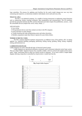
Here the efforts are made to develop a electro pneumatic circuit for a shaping operations using a shaper
machine. This makes the operations semi automatic producing shaping operations by a single point cutting tool.
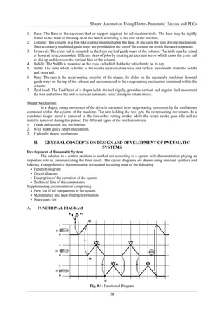
The three movements of the shaper are
a) The reciprocating movement of the ram.
b) The Crosswise movement of the tool lead across the cross rail.
c) The vertical up and down movement of the table.
The above movements are being automated using electropneumatic components such as pneumatic
cylinders, direction control valves, flow control valves and other electrical and electronics devices.
For automation of the shaper, an electropneumatic circuit is developed with the help of sensors,
solenoids, electrical and electronic devices. The electro pneumatic circuit developed is simulated, executed and
will be interfaced with PLCs, L10/L20 manufactured by BOSCH – REXROTH Germany. A prototype of the set
up is also planned for better understanding and demonstration purpose.
Keywords:- Automation, Electropneumatic Devices, cutting tool, automated DCVs, Electrical and Electronic
Devices
I. INTRODUCTION
The shaper is a reciprocating type of machine tool intended primarily to produce flat surfaces. The
metal working shaper was developed in the year 1836 by James Nasmyth an Englishman.
The Shaper machine tool holds and locates a work piece on a table and machines or cuts the work piece
by feeding it against a reciprocating single point cutting tool. When the horizontal surface is being machined the
table automatically feeds the work to the cutting tool on each return stroke of the ram. The surfaces cut by the
shaper may be horizontal, vertical or inclined.
Principal Parts of a Shaper:
The following figure illustrates the different parts of a standard shaper.
[Fig-1]
2. Shaper Automation Using Electro-Pneumatic Devices and PLCs
50
1. Base: The Base is the necessary bed or support required for all machine tools. The base may be rigidly
bolted to the floor of the shop or on the bench according to the size of the machine.
2. Column: The column is a box like casting mounted upon the base. It encloses the ram driving mechanism.
Two accurately machined guide ways are provided on the top of the column on which the ram reciprocate.
3. Cross rail: The cross rail is mounted on the front vertical guide ways of the column. The table may be raised
or lowered to accommodate different sizes of jobs by rotating an elevated screw which cases the cross rail
to slid up and down on the vertical face of the column.
4. Saddle: The Saddle is mounted on the cross rail which holds the table firmly on its top.
5. Table: The table which is bolted to the saddle receives cross wise and vertical movements from the saddle
and cross rail.
6. Ram: The ram is the reciprocating member of the shaper. Its slides on the accurately machined dovetail
guide ways on the top of the column and are connected to the reciprocating mechanism contained within the
column.
7. Tool head: The Tool head of a shaper holds the tool rigidly, provides vertical and angular feed movement
the tool and allows the tool to have an automatic relief during its return stroke.
Shaper Mechanism:
In a shaper, rotary movement of the drive is converted in to reciprocating movement by the mechanism
contained within the column of the machine. The ram holding the tool gets the reciprocating movement. In a
slandered shaper metal is removed in the forwarded cutting stroke, while the return stroke goes idle and no
metal is removed during this period. The different types of the mechanisms are
1. Crank and slotted link mechanism.
2. Whit worth quick return mechanism.
3. Hydraulic shaper mechanism.
II. GENERAL CONCEPTS ON DESIGN AND DEVELOPMENT OF PNEUMATIC
SYSTEMS
Development of Pneumatic System
The solution to a control problem is worked out according to a system with documentation playing an
important role in communicating the final result. The circuit diagrams are drawn using standard symbols and
labeling. Comprehensive documentation is required including most of the following
Function diagram
Circuit diagram
Description of the operation of the system
Technical data of the components.
Supplementary documentation comprising
Parts list of all components in the system
Maintenance and fault-finding information
Spare parts list
A. FUNCTIONAL DIAGRAM
Fig. 8.1: Functional Diagram
3. Shaper Automation Using Electro-Pneumatic Devices and PLCs
51
In majority of the pneumatic applications more than one cylinder is used. The movement of these
cylinders is coordinated as per the required sequence.
The activation of the limit switches of different cylinders will provide set or reset signal to the final
control valves for further controlling the movement of various cylinders.
The limit switches have to be arranged in the proper location with the help of motion diagram.
In order to develop control circuitry for multicylinder applications, it is necessary to draw the motion diagram to
understand the sequence of actuation of various signal input switches-limit switches and sensors. Multicylinder
applications with three cylinders A, B and C.
The status of the cylinder displacement and actuation of set and reset signals at single piloted
directional control value is shown by functional diagram.
Fig-Functional Diagram
In majority of the pneumatic application more than one cylinder is used. The movement of these
cylinder is co-ordinated as per the required sequence.
In order to develop control circuitry for multi cylinder application, it is necessary to draw the motion or
functional diagram, by which one will be able to understand the sequence of actuation of various signal input,
by limit switches and sensors.
The functional or motion diagram is that, in which graphically the sequence of operation of each
cylinder is shown and it also shows the actuation of each cylinder by the cylinder switches.
In the functional diagram, all the three cylinder are shown according to the sequence of operation. One
cylinder has to position i.e. 0 and 1 position.
„0‟ - indicates that the piston of cylinder is at backward position.
„1‟ - indicates that the piston of the cylinder is at extreme forward position.
Description of the functional diagram of a planer:
To start with, the push button switch S1 is pressed, cylinder switch „B1‟ is already in actuation mode it
sends signal to solenoid Y1 by which the piston of the cylinder „1‟ moves forward, which clamps the
component.
As, soon as the piston reaches to cylinder switch B2, it sends signal to solenoid Y2 by which the 2nd
cylinder piston moves forward, resulting in cutting operation. As the piston of the cylinder-2 reaches to,
cylinder switch „B4‟ a loop is formed and the piston of the cylinder-2 retracts as the solenoid Y2 de-energies.
As soon as the piston of the cylinder 2 reaches the backward position it activates cylinder switch B3,
which sends the signal to solenoid coil „Y3‟, the piston of cylinder „3‟ moves forward making a cross feed of the
tool head.
When, the piston of the cylinder 3 reaches the cylinder switch „B6‟ a loop is formed by which it
interrupts the voltage supply to the solenoid coil „Y4‟. Thus the piston of the cylinder „3‟ retracts.
The movement of cylinder „2‟ and cylinder „3‟ in sequence continues till the change over switch is
operated. When the change over switch is operated, the voltage supply to the valve solenoid Y1 is interrupted,
the voltage supply to valve, solenoid „Y1‟ by which the piston of the cylinder „1‟ retracts, unclamping the
component.
Thus the whole circuit is reset and the machine stops.
B: PNEUMATIC CIRCUIT DIAGRAM OF THREE (03) DOUBLE ACTING CYLINDERS
Fig. Pneumatic Circuit diagram of 3 cylinders
Pneumatic circuit diagram
The 3 double-acting cylinders are controlled with 5/2 directional control valves.
The valves are equipped with visual display and manual override.
Valve 1 has the solenoid coils designated Yl, valve 2 has solenoid designated as Y2 and valve 3 has coil
designated as Y3
4. Shaper Automation Using Electro-Pneumatic Devices and PLCs
52
When signal voltage is applied to the solenoid coils Yl, Y2 and Y3, the cylinders extend, when voltage is
interrupted to the solenoid the cylinder retract.
The extension speed of all 3 cylinders can be infinitely adjusted with a one-way flow control valves
C: ELECTRICAL CIRCUIT DIAGRAM
Fig. Electrical Circuit diagram
CONTROL SECTION:
The control section of the electric circuit diagram consist of a standing step sequence diagram with 6
steps (6 storing step and 1 reset by C.O.S.) which are made up of the relays K1 to K6 and the assigned latching
circuits.
Control switch S1 is actuated, signaler B1 is actuated and signals B2, B4, B3, B6 and B5 are switched by
the sequence order.
In this order, one latching cicuit (step) is respectively set.
Signal B5 triggers the reset step at line 3.
The first latching circuit is not broken, but line No. 3 is reset by normal closed contact K6 in current path 3.
This causes all further latching circuits (steps) to be reset from left to right. Now as contact point K1 is
closed the continuity of current will energize coil K2.
Thus the cylce continues from line no. 3 to line no. 12 the change over switch is operated in the line no. 1 to
stop the maching cycle.
POWER SECTION:
In the power section, the contact point switches the valve solenoids corresponding to the step sequence.
When using single solenoid spring return valve, there is need of continuous signals, when voltage is
present at one side, the valve is operated and when there is no voltage, the valve goes to its initial position
by means of spring force.
Step 1: Contact K1 in current path 13 switches Y1 solenoid cylinder 1 extends and actuate the cylinder
switch B2.
Step 2: Contact K2 in current path 14 switches the valve solenoid Y2 via the unopened normally closed
contact K3 cylinder 2 extends and actuates cylinder switch B4.
Step 3: Contact K3 in current path 14 normally closed contact, now changes to normally open, and cut the
current path in line 14 thus the solenoid Y2 collapse, the valve regains its original position by which the
cylinder 2 piston retracts actuating the cylinder switch B3.
Step 4: Contact K4 in current path 15 switches valve solenoid Y3 via the unopened normally closed contact
K5, then cylinder 3 extends and actuates cylinder switch B6.
Step 5: Contact K5 in current path 15 switch off Y3, as K5 is normally closed, now changes to normally
open which interrupts the voltage to Y3 and cylinder 3 retracts thus actuating actual cylinder switch B5.
Step 6: Contact K6 in current path 3 interrupts the current supply on line 3 to relay coil K2 where all the
other lines are reset. The step sequence continues in the cylinder 2 and 3.
Step 7: To stop the machining cycle completely the change over switch provided in line No. 1 when
operated will reset the whole circuit. The machine stops.
5. Shaper Automation Using Electro-Pneumatic Devices and PLCs
53
TASK:
Conversion of conventional shaper into a automated machine:
The component to be machined is placed on the table and when the push button switch is operated, the first
cylinder will clamp the component. After clamping operation, the signal is sent to the Y2 solenoid by which
the second cylinder actuate, so the ram of the shaper reciprocate and does the cutting operation.
After taking one cut the cylinder 2 sends the signal to the Y3 solenoid by which the cylinder 3 actuates so
that cylinder the 3 extends inturn rotates a screw by a ratchet and pawl mechanism, the crosswise movement
of the table is obtained (feed).
Once the feed is given the cylinder 3 sends the signal to cylinder 2 so that the ram operates, taking a cut.
Thus the cycle continue till the machining of the component is completed.
Once the machining of the component is over, the change over switch is actuated by which the machine
stops and the component is unclamped. The electrical circuit is reset.
The work piece is manually taken out of the table and the table is brought back to the original position with
the help of a screw.
Electrically controlled 5/2 single solenoid spring returned DCV are used as actuator.
Signals used are electrical cylinder switch (Magnetic field sensors or reed switches).
The extension speed of all the 3 cylinder are variable, adjustable, by the flow control check valve.
D: IMPLEMENTATION
CONVERSION OF MANUALLY OPERATED SHAPER INTO THE AUTOMATIC UNIT:
In case of conversion of the machine we need 3 double acting cylinder. One cylinder for clamping the job,
the second cylinder for reciprocating the ram and the third cylinder for operating the cross slide screw
(feed).
Six proximity magnetic switches, two each for one cylinder, one change over switch, 3 DCV 5/2 single
solenoid spring returned, 3 variable flow control valve, one pressure relief valve, compressor and the
flexible pipes for necessary connections are required.
12 V DC power supply, relay system, push button switch, PLC and wires for connection are also used.
WORKING OF THE MACHINE:
To start, the push button switch is pressed. The cylinder mounted on the table will move slowly for
clamping the job. Once the clamping is over the switch B2 sends the signal to Y2 solenoid, so that the
piston of the cylinder 2 moves forward moving the ram. Thus the cutting or machining stroke, takes place
and the piston moves along with the ram.
As the piston of cylinder 2 returns to its extreme backward position, the cylinder switch B3 will send the
signal to solenoid Y3 by which the piston of cylinder 3 moves forward by which the cross feeding screw is
rotated with the help of ratchet and pawl mechanism. When the piston of cylinder 3 reaches its forward
position, and it returns back quickly and as the piston reaches to its extreme backward position, magnetic
switch B5, sends the signal to solenoid Y2 causing the cylinder 2 to move. This process continues till the
table of the machine comes in contact with the change over switch. The complete electrical circuit and is
reset the machine is stopped.
E: INTERFACING THE SHAPER OPERATION WITH PLC
HISTORY OF PLC:
Before the PLC, control, sequencing, and safety interlock logic for manufacturing automobiles and was
accomplished by using hundreds or thousands of relays, cam timers, and drum sequencers and dedicated closed-
6. Shaper Automation Using Electro-Pneumatic Devices and PLCs
54
loop controllers. The process for updating such facilities for the yearly model change-over was very time
consuming and expensive, as electricians needed to individually rewire each and every relay.
WHAT IS A PLC:
The PLC is an industrial computer. It is capable of storing instructions to implement control functions
such as sequencing, timing, counting, arithmetic, data manipulation and communication. The I/O interfaces
provide the connection between the PLC and the information providers (inputs like pushbuttons, sensors,...) and
the controllable devices (outputs like valves, relays, lamps,...).
ADVANTAGES:
Less wiring.
Wiring between devices and relay contacts are done in the PLC program.
Easier and faster to make changes.
Trouble shooting aids make programming easier and reduce downtime.
Reliable components make these likely to operate for years before failure.
WHERE IS THE PLC USED:
The PLC controls industrial machines and processes. In different areas of the industry, PLC are being
applied, e.g.: materials handling, packaging, palletizing, milling, boring, grinding, filling, sorting, weighing,
mining, petrochemicals etc.
LADDER DIAGRAM (LD)
Ladder diagrams are used to describe the logic of electrical control system.
Ladder diagrams are specialized schematics commonly used to document industrial control logic system.
They are called “ladder” diagrams because they resemble a ladder, with two vertical rails (supply power) and as
many “rungs” (horizontal lines) as there are control circuits to represent. If we want to draw a simple ladder
diagram showing a lamp that is controlled by a hand switch, it would look like this.
Fig. Simple ladder diagram
7. Shaper Automation Using Electro-Pneumatic Devices and PLCs
55
F: OPERATIONAL ANALYSIS
OPERATIONAL ANALYSIS OF MANUAL AND AUTOMATED SHAPER MACHINE:
Depending upon the size of the machine the cost varies. Let us consider a minimum size of the machine
and do the analysis.
PRODUCTION TIME:
Lets us consider a square flat M.S plate with a 50x50 mm and thickness 5mm in which the top face has to
be machined flat.
MANUALLY OPERATED SHAPER MACHINE:
The time need to produce one flat plate is 6 minutes.
Total number of components produced in one hour is 10 nos.
Therefore in one day 100 components are machined (total machining time taken in a day is 10 hours).
AUTOMATED SHAPER MACHINE:
The time need to produce one flat plate is one minute. Total number of components machined in one hour,
60 components.
Therefore in one day 600 components are machined (total machining time taken in a day is 10 hours).
As seen from the graph the rate of production is very high in case of the automated machine as compared
with the manually operated machine. Hence the productivity is high on the automatic machines.
III CONCLUSION
The conventional controlled machines are converted into automatic machine by which maximum operating
time will be saved. Thus the output of the product will be increased. The human interventions during the
machining operations are reduced. As far as this project is concerned, the machine is not fully converted
into automatic machine but it is converted as a semi automatic machine, because the loading and unloading
of the workpiece is done manually.
But this machine can be made fully automatic by using more number of cylinders by which the work-piece
is loaded automatically. By doing so the machine may run for longer time and loading and unloading can be
made without stopping the machine. The number of workers are also reduced and by which the number of
machines can be operated by a single operator.
To conclude, this project is made keeping in mind that, any conventionally operated machines can be
converted into automatic or semi automatic machines by using these devices. Late the machine is
interfaced with PLCs. For this purpose one should have the full knowhow of the devices which are being
8. Shaper Automation Using Electro-Pneumatic Devices and PLCs
56
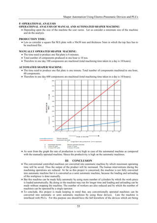
used. By doing so the existing old machines can be modified and made automatic and the procuring cost
automatic machines may be reduced. Thus there is a lot of scope in this area (automation).
Hence there is still wide scope in the automation area where lots of improvement can be made with the help
of the latest technology.
REFERENCES
[1]. Fluid power controls- Anthony Espisito
[2]. Pneumatic controls – Joji P
[3]. Pneumatic controls manual- FESTO
[4]. Hydraulic and Pneumatic Manuals- Bosch Rexroth
[5]. Low cost Automation using Electro Pneumatic system –an online case study in multi station part
transfer, drilling and tapping machine.
[6]. Low cost Automation.
[7]. Design of structured controller satisfying loop shaping using evolutionary optimization: application to
a pneumatic robot Arm.
[8]. The design and development of a rock cutting machine for gold mining.
[9]. The research and application of Hydraulics and Pneumatics in Huazhong University of science and
technology.
[10]. Design of Hydraulic circuit for CNC lathe machine converted from conventional lathe machine.
[11]. Pneumatic and Automation – www.vivekengineers.net Valve automation, Pneumatic devices, electrical
control actuators by Control Technology.
[12]. Control Automation by Sean Davies.
[13]. Flexible Manufacturing control with PLCs, CNC and software agents – Ronald Schoop.
[14]. Automatic Velocity Control in cutting of machines by Carlos Machado, Jaime Fonseca and Jose
Mendes.
[15]. Machine Tools and Automation by H.P. Potts.
[16]. CAD/CAM/CIM – New Age Publication.Computer –Aided design and manufacturing – Mikell P.
Groover