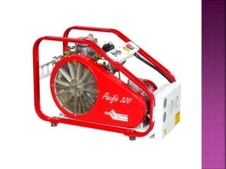
1) An air powered engine works by using compressed air stored in a high-pressure tank to power the engine instead of gasoline.
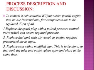
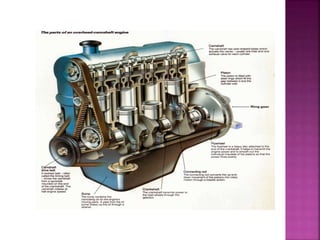
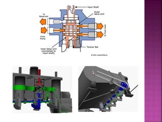
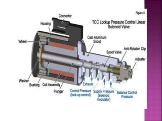
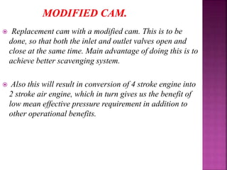
2) It can be created by modifying a conventional internal combustion engine to use compressed air and pulsed pressure control valves instead of gasoline and spark plugs.
3) The main benefits are that it does not require expensive fossil fuels and has fewer emissions, simpler design, and lower maintenance costs than gasoline engines. However, compressing the air is energy intensive and the engine has lower power and efficiency than gasoline engines.


![Getting Started with Apache Spark: Big Data Made Simple [Free Meetup]](https://cdn.slidesharecdn.com/ss_thumbnails/apachesparkgettingstarted-260203175547-8361bcc3-thumbnail.jpg?width=640&height=640&fit=bounds)


