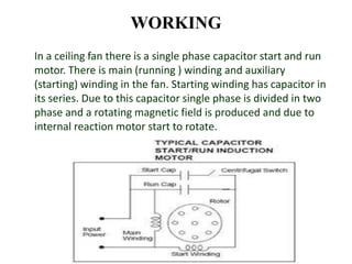
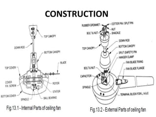
CEILING FAN
OBJECTIVE :
To study the working, construction
And troubleshooting of Ceiling Fan
INTRODUCTION
• A ceiling fan is a device
suspended from the ceiling of a
room, which employs hub-
mounted rotating paddles to
circulate air.
• First electrically powered fan was
invented in 1882 by Philip Diehl.
• Crompton Greaves Ltd is the
leading manufacturer of fans.
PRINCIPLE
If a current carrying
conductor is placed in
a magnetic field it
experience a force
and start to rotate.
The direction of
rotation can be found
by Fleming’s Left Hand
Rule.
WORKING
In a ceiling fan there is a single phase capacitor start and run
motor. There is main (running ) winding and auxiliary
(starting) winding in the fan. Starting winding has capacitor in
its series. Due to this capacitor single phase is divided in two
phase and a rotating magnetic field is produced and due to
internal reaction motor start to rotate.
Schematic Circuit Diagram of
Ceiling Fan & Regulator Connection
CONSTRUCTION
KEY COMPONENTS
1. Electric Motor – Capacitor Start & Run, rated at
230V,50Hz
2. Blades – Usually made of Aluminum sheets, 120
degree and normally 3-4 blades
3. Blade Flanges
4. Canopy/Switch Cup
5. Suspension/Down rod
6. Ball Bearing
7. Terminal Box (L,N & E)
Fan Regulator
TROUBLESHOOTING
CHART
TESTING OF EARTH FAULT
• Make the arrangement as
per circuit diagram and see
the light effect of bulb-
• If bulb gives light: There is
earth fault i.e. leakage of
current in the metallic part
of fan’ body.
• Check and remove it before
using.
• If bulb gives no light: No
earth fault i.e. no leakage of
current in the body of fan.
PRECAUTIONS
• Before hanging fan all
testing should be done
properly.
• Fan’s body (metallic part)
should be earthed .
• Nut bolt should be tighten
correctly.
• Locking pin should be used.
• Connection should not be
lose.
Ceiling fan
Ceiling fan

Ceiling fan

  • 1.
    CEILING FAN OBJECTIVE : Tostudy the working, construction And troubleshooting of Ceiling Fan
  • 2.
    INTRODUCTION • A ceilingfan is a device suspended from the ceiling of a room, which employs hub- mounted rotating paddles to circulate air. • First electrically powered fan was invented in 1882 by Philip Diehl. • Crompton Greaves Ltd is the leading manufacturer of fans.
  • 3.
    PRINCIPLE If a currentcarrying conductor is placed in a magnetic field it experience a force and start to rotate. The direction of rotation can be found by Fleming’s Left Hand Rule.
  • 4.
    WORKING In a ceilingfan there is a single phase capacitor start and run motor. There is main (running ) winding and auxiliary (starting) winding in the fan. Starting winding has capacitor in its series. Due to this capacitor single phase is divided in two phase and a rotating magnetic field is produced and due to internal reaction motor start to rotate.
  • 5.
    Schematic Circuit Diagramof Ceiling Fan & Regulator Connection
  • 6.
  • 7.
    KEY COMPONENTS 1. ElectricMotor – Capacitor Start & Run, rated at 230V,50Hz 2. Blades – Usually made of Aluminum sheets, 120 degree and normally 3-4 blades 3. Blade Flanges 4. Canopy/Switch Cup 5. Suspension/Down rod 6. Ball Bearing 7. Terminal Box (L,N & E)
  • 8.
  • 10.
  • 13.
    TESTING OF EARTHFAULT • Make the arrangement as per circuit diagram and see the light effect of bulb- • If bulb gives light: There is earth fault i.e. leakage of current in the metallic part of fan’ body. • Check and remove it before using. • If bulb gives no light: No earth fault i.e. no leakage of current in the body of fan.
  • 14.
    PRECAUTIONS • Before hangingfan all testing should be done properly. • Fan’s body (metallic part) should be earthed . • Nut bolt should be tighten correctly. • Locking pin should be used. • Connection should not be lose.