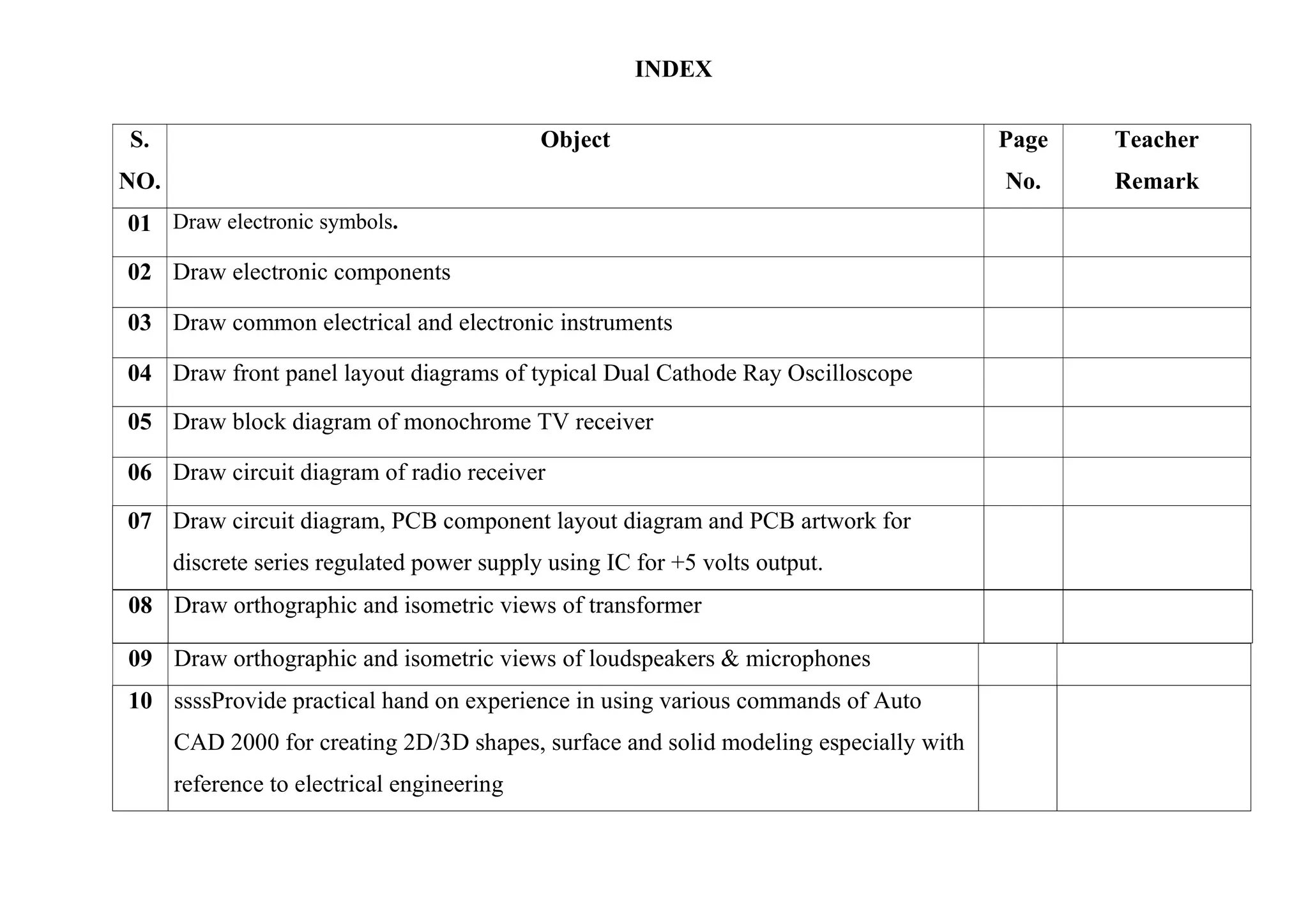
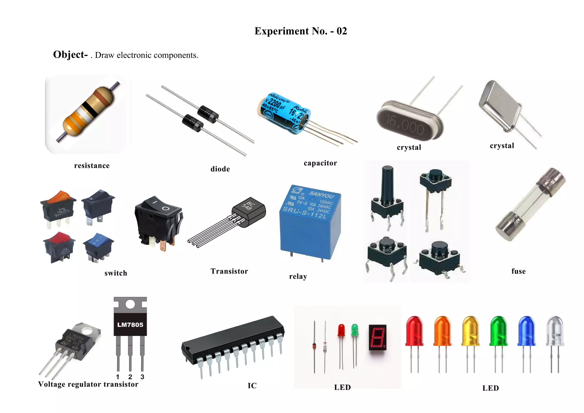
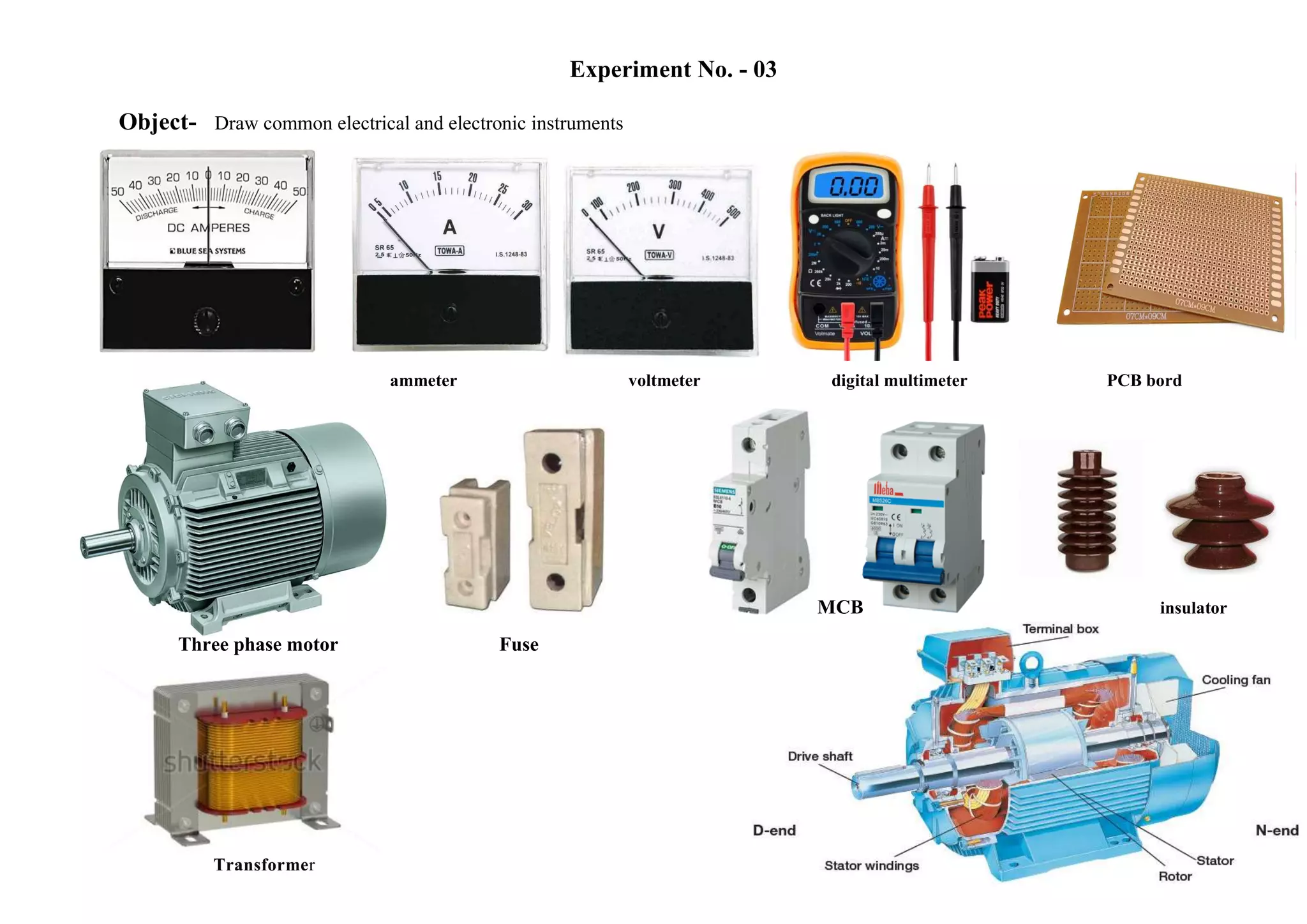
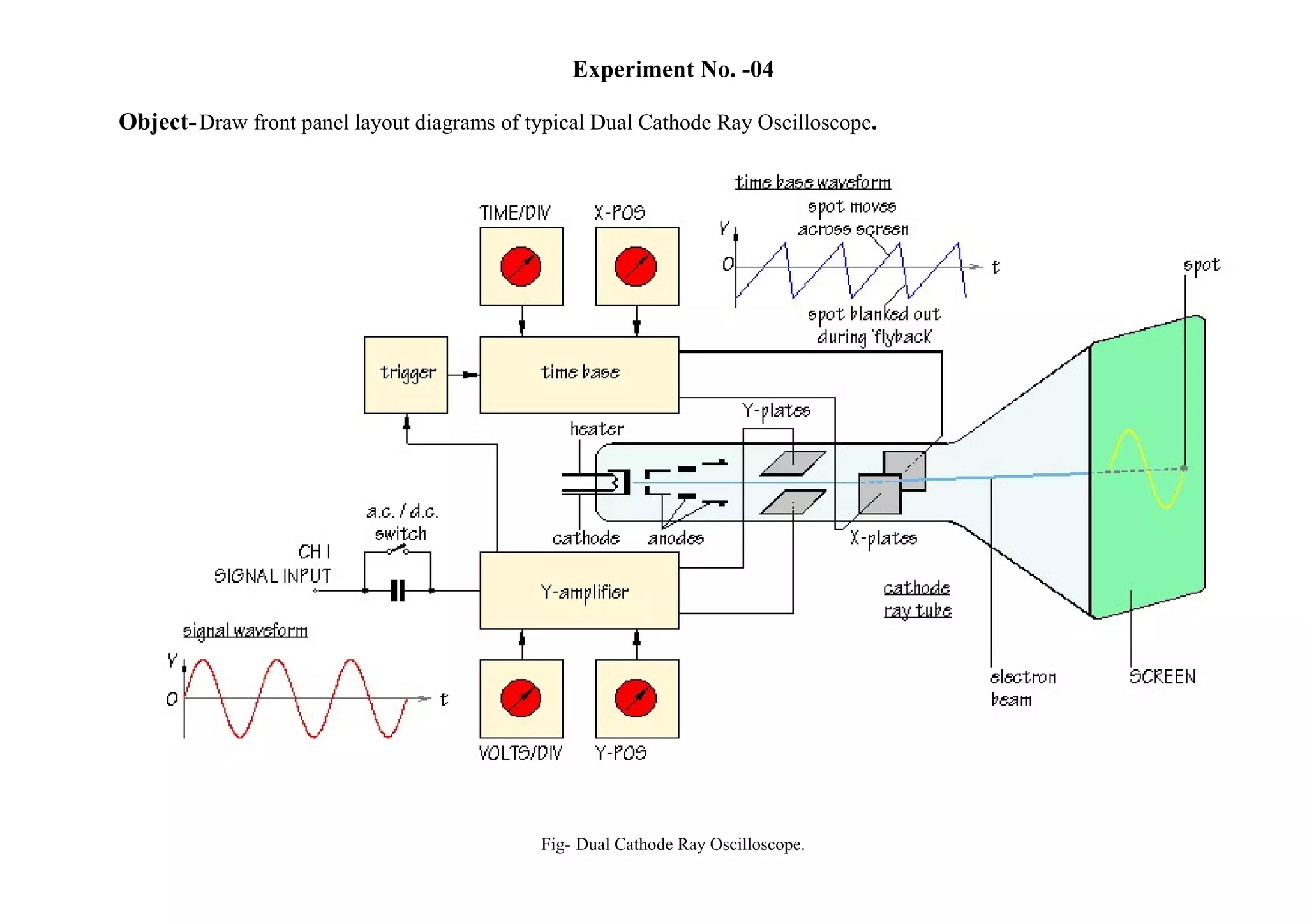
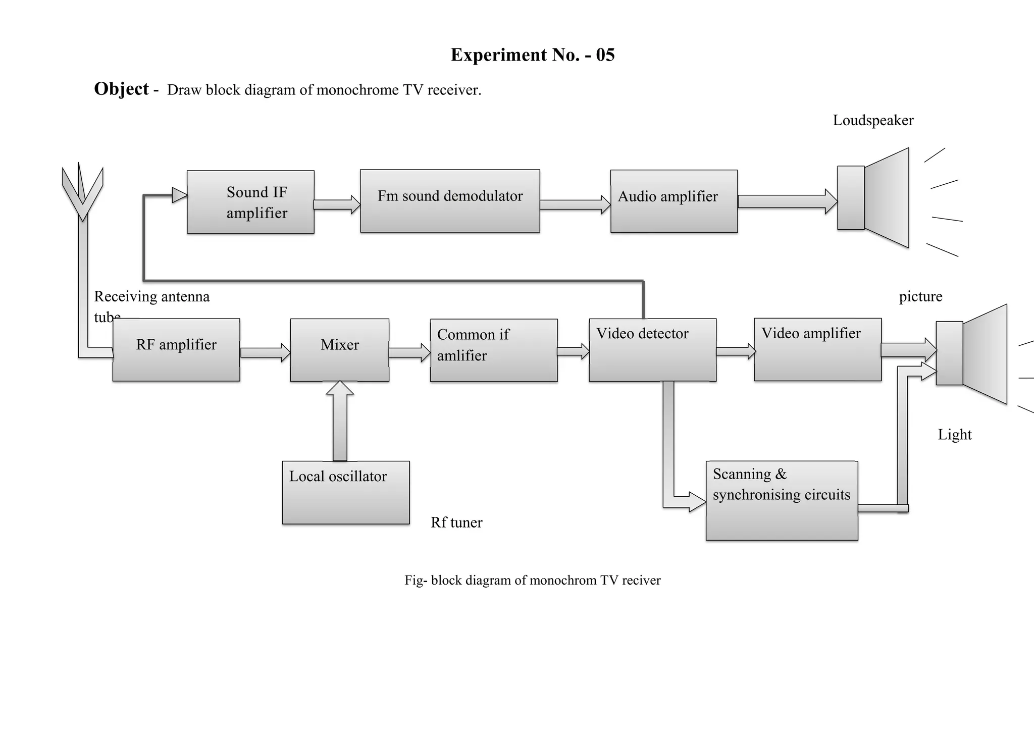
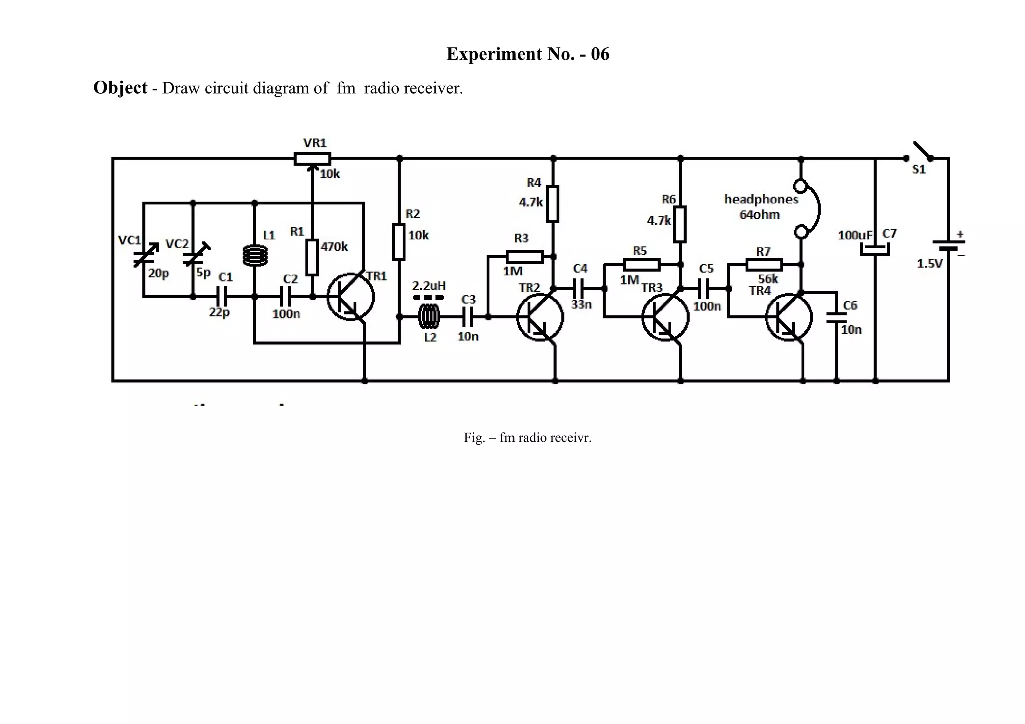
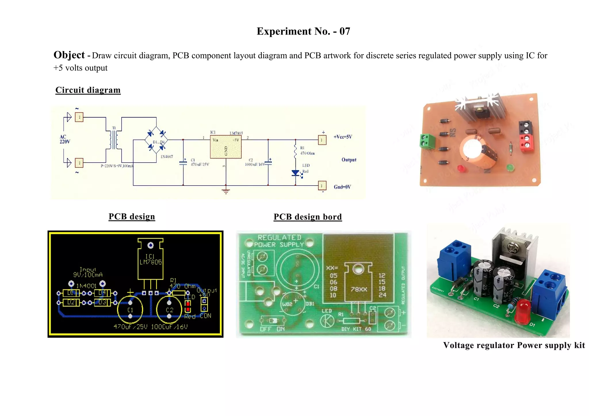
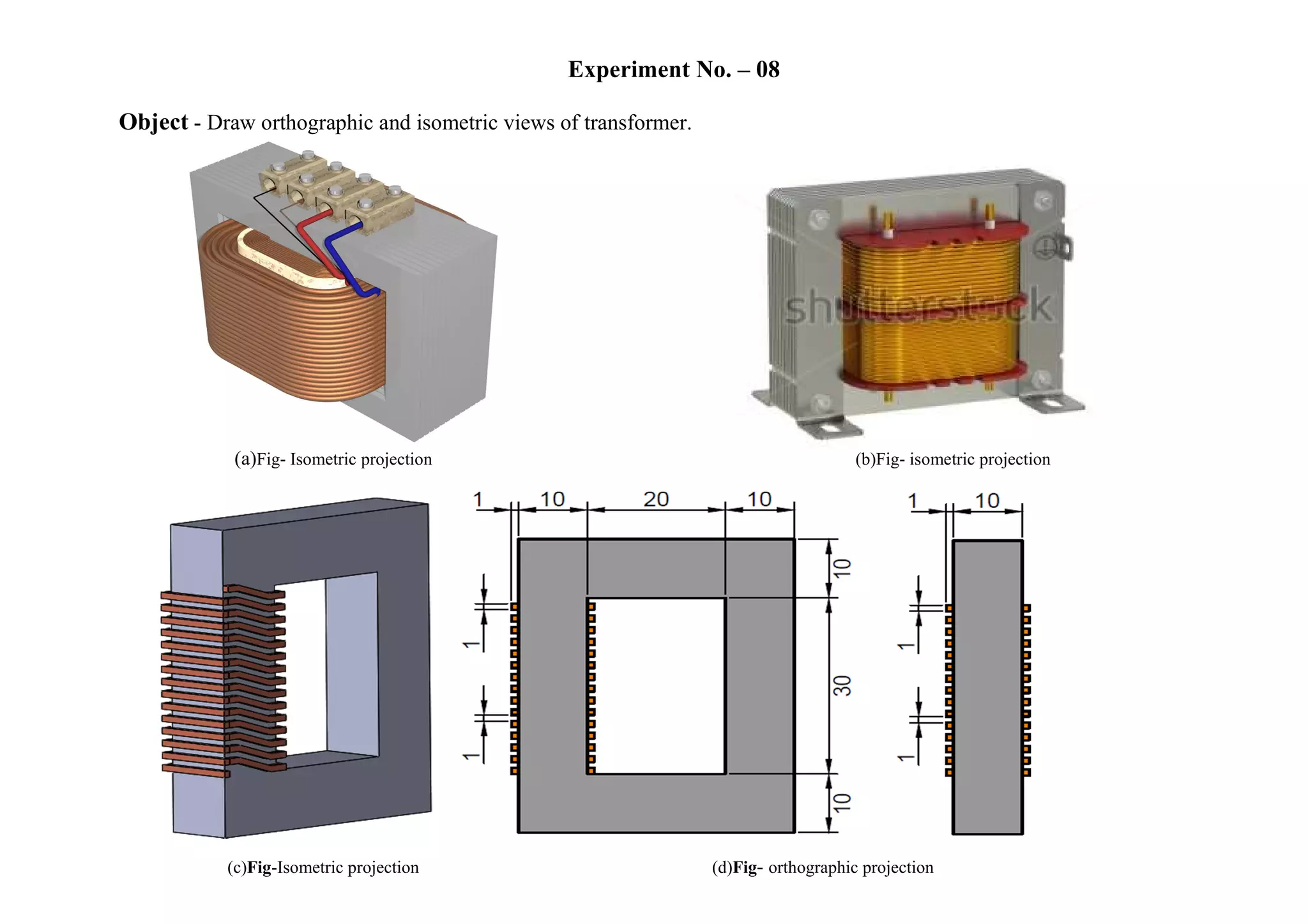
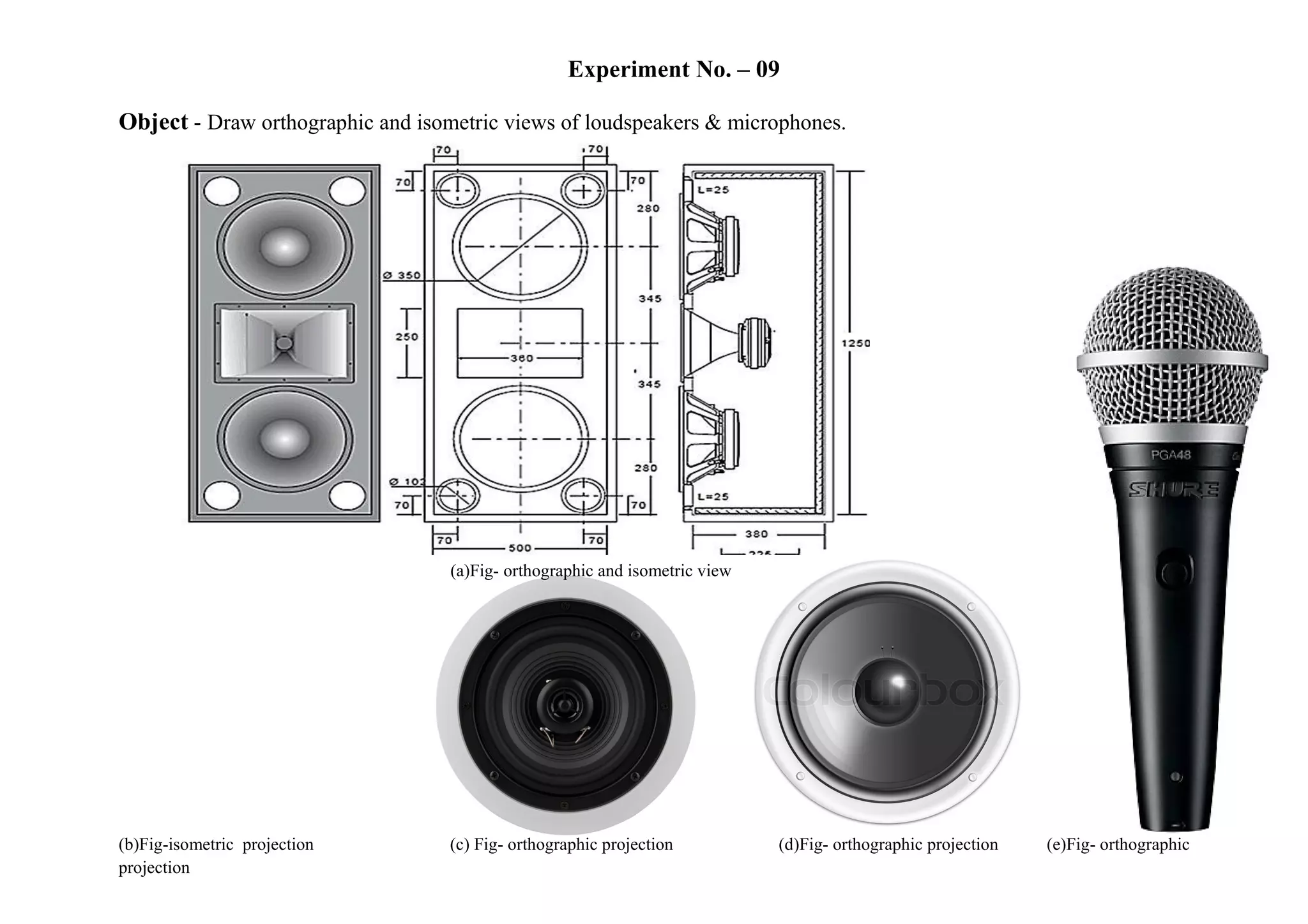
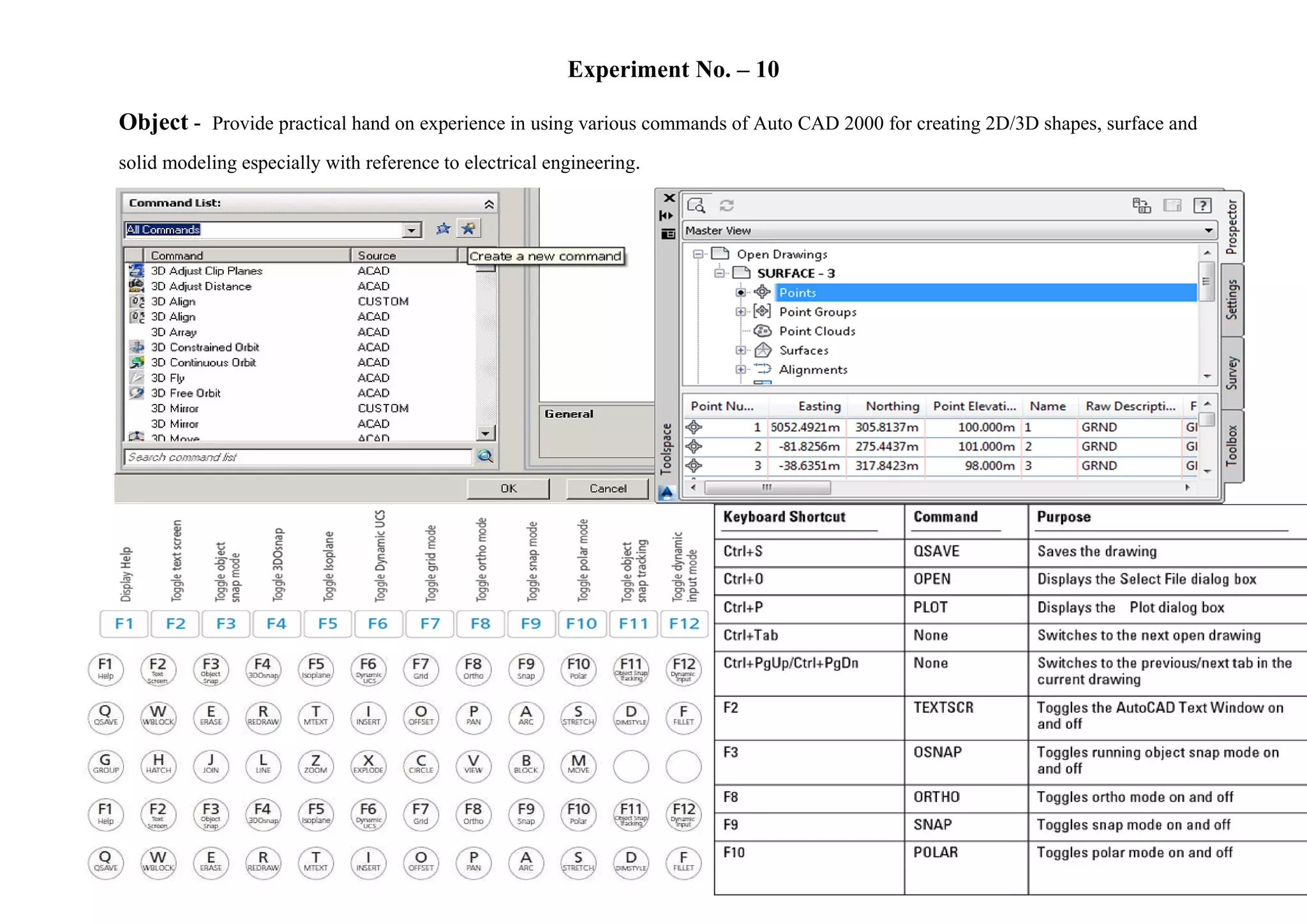
Project report
On.
COMPUTER AIDED DESIGN & DRAFTING LAB
SUBMMITED TO SUBMMITED BY
NARENDRA KUMAR DEWANGAN OMPRAKASH SAHU
ET&T 3rd
year 5th
sem.
Roll No.-2682815019
INDEX
S.
NO.
Object Page
No.
Teacher
Remark
01 Draw electronic symbols.
02 Draw electronic components
03 Draw common electrical and electronic instruments
04 Draw front panel layout diagrams of typical Dual Cathode Ray Oscilloscope
05 Draw block diagram of monochrome TV receiver
06 Draw circuit diagram of radio receiver
07 Draw circuit diagram, PCB component layout diagram and PCB artwork for
discrete series regulated power supply using IC for +5 volts output.
08 Draw orthographic and isometric views of transformer
09 Draw orthographic and isometric views of loudspeakers & microphones
10 ssssProvide practical hand on experience in using various commands of Auto
CAD 2000 for creating 2D/3D shapes, surface and solid modeling especially with
reference to electrical engineering
Experiment No. - 02
Object- . Draw electronic components.
Experiment No. - 03
Object- Draw common electrical and electronic instruments
ammeter voltmeter digital multimeter PCB bord
MCB insulator
Three phase motor Fuse
Experiment No. -04
Object-Draw front panel layout diagrams of typical Dual Cathode Ray Oscilloscope.
Fig- Dual Cathode Ray Oscilloscope.
Experiment No. - 05
Object - Draw block diagram of monochrome TV receiver.
Loudspeaker
Receiving antenna picture
tube
Light
Rf tuner
Fig- block diagram of monochrom TV reciver
Scanning &
synchronising circuits
Local oscillator
Video amplifierVideo detectorCommon if
amlifier
MixerRF amplifier
Audio amplifierFm sound demodulator
Experiment No. - 06
Object - Draw circuit diagram of fm radio receiver.
Fig. – fm radio receivr.
Experiment No. - 07
Object -Draw circuit diagram, PCB component layout diagram and PCB artwork for discrete series regulated power supply using IC for
+5 volts output
Experiment No. – 08
Object - Draw orthographic and isometric views of transformer.
(a)Fig- Isometric projection (b)Fig- isometric projection
(c)Fig-Isometric projection (d)Fig- orthographic projection
Experiment No. – 09
Object - Draw orthographic and isometric views of loudspeakers & microphones.
(a)Fig- orthographic and isometric view
(b)Fig-isometric projection (c) Fig- orthographic projection (d)Fig- orthographic projection (e)Fig- orthographic
projection
Experiment No. – 10
Object - Provide practical hand on experience in using various commands of Auto CAD 2000 for creating 2D/3D shapes, surface and
solid modeling especially with reference to electrical engineering.

ET&T 5th sem. diploma in eing. Cadd file 2-10 experimants opsahu

  • 1.
    Project report On. COMPUTER AIDEDDESIGN & DRAFTING LAB SUBMMITED TO SUBMMITED BY NARENDRA KUMAR DEWANGAN OMPRAKASH SAHU ET&T 3rd year 5th sem. Roll No.-2682815019
  • 2.
    INDEX S. NO. Object Page No. Teacher Remark 01 Drawelectronic symbols. 02 Draw electronic components 03 Draw common electrical and electronic instruments 04 Draw front panel layout diagrams of typical Dual Cathode Ray Oscilloscope 05 Draw block diagram of monochrome TV receiver 06 Draw circuit diagram of radio receiver 07 Draw circuit diagram, PCB component layout diagram and PCB artwork for discrete series regulated power supply using IC for +5 volts output. 08 Draw orthographic and isometric views of transformer 09 Draw orthographic and isometric views of loudspeakers & microphones 10 ssssProvide practical hand on experience in using various commands of Auto CAD 2000 for creating 2D/3D shapes, surface and solid modeling especially with reference to electrical engineering
  • 3.
    Experiment No. -02 Object- . Draw electronic components.
  • 4.
    Experiment No. -03 Object- Draw common electrical and electronic instruments ammeter voltmeter digital multimeter PCB bord MCB insulator Three phase motor Fuse
  • 5.
    Experiment No. -04 Object-Drawfront panel layout diagrams of typical Dual Cathode Ray Oscilloscope. Fig- Dual Cathode Ray Oscilloscope.
  • 6.
    Experiment No. -05 Object - Draw block diagram of monochrome TV receiver. Loudspeaker Receiving antenna picture tube Light Rf tuner Fig- block diagram of monochrom TV reciver Scanning & synchronising circuits Local oscillator Video amplifierVideo detectorCommon if amlifier MixerRF amplifier Audio amplifierFm sound demodulator
  • 7.
    Experiment No. -06 Object - Draw circuit diagram of fm radio receiver. Fig. – fm radio receivr.
  • 8.
    Experiment No. -07 Object -Draw circuit diagram, PCB component layout diagram and PCB artwork for discrete series regulated power supply using IC for +5 volts output
  • 9.
    Experiment No. –08 Object - Draw orthographic and isometric views of transformer. (a)Fig- Isometric projection (b)Fig- isometric projection (c)Fig-Isometric projection (d)Fig- orthographic projection
  • 10.
    Experiment No. –09 Object - Draw orthographic and isometric views of loudspeakers & microphones. (a)Fig- orthographic and isometric view (b)Fig-isometric projection (c) Fig- orthographic projection (d)Fig- orthographic projection (e)Fig- orthographic projection
  • 11.
    Experiment No. –10 Object - Provide practical hand on experience in using various commands of Auto CAD 2000 for creating 2D/3D shapes, surface and solid modeling especially with reference to electrical engineering.