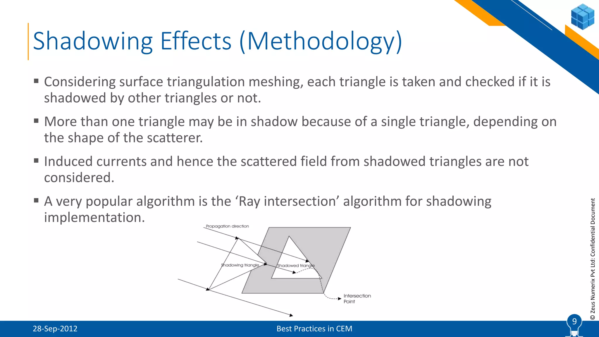
SlideShare a Scribd company logo
1 of 19
1Built-to-Spec | Product Approval | Engineering Services | Software Development
CEM of High Frequency
Methods
Various methods to solve high frequency
electromagnetics
2
©ZeusNumerixPvtLtd:ConfidentialDocument
Overview
28-Sep-2012 Best Practices in CEM
 Introduction
 Comparison of Physical Optics with Geometric Optics
 Physical optics formulation (PO)
 Shadowing effects for PO
 Equivalent edge currents formulation (PTD)
 Shooting And Bouncing Ray methodology (SBR)
 Surface currents for PO, flash point analysis
 Conclusion
2
3
©ZeusNumerixPvtLtd:ConfidentialDocument
Introduction
28-Sep-2012 Best Practices in CEM
 When a perfectly conducting body is illuminated by an electromagnetic field, electric
currents are induced on the surface of the body.
 These currents act as new sources and create an electromagnetic field radiated
outward from the body.
 This field, called the scattered field, depends on the frequency and the polarization
of the incident field.
 Radar Cross Section (RCS), which is the fictitious area of the target, characterizes the
spatial distribution of the power of the scattered field.
 Among high frequency scattering techniques, Physical Optics (PO) and Geometric
Optics (GO) are the most popular methods.
3
4
©ZeusNumerixPvtLtd:ConfidentialDocument
Comparison of GO and PO
28-Sep-2012 Best Practices in CEM
 GO is based on the classical ray-tracing of incident, reflected and transmitted rays
while PO is based on the integration of induced currents predicted by GO.
 According to GO, RCS is given by a simple formula that involves the local radius of
curvature at the specular point. Prediction fails when radius of curvature becomes
infinite.
 The PO surface integral approach gives the correct result around the specular
direction.
4
5
©ZeusNumerixPvtLtd:ConfidentialDocument
Theoretical Background (PO)
28-Sep-2012 Best Practices in CEM
 PO uses the following steps in order to find the scattered field:
 The incident and reflected fields on the surface of the scatterer is found by
Geometrical Optics.
 The current excited on the surface of the scatterer is found by the tangential
components of the incident fields on the surface.
 The PO current for a conducting body is given by:
 Illuminated region:
 Shadowed region:
 Using radiation integrals, PO surface current is integrated over the surface of the
scatterer, to yield the scattered field
5
𝐽𝑆 = 0
𝐽𝑆 = 0
6
©ZeusNumerixPvtLtd:ConfidentialDocument
Theoretical Background (PO)
28-Sep-2012 Best Practices in CEM
 The total PO field is given by the superposition of the incident and the scattered
fields:
 The incident electric and magnetic fields are given by the following expressions:
 Relation between incident magnetic and electric field:
6
𝐻 𝑖
= ( 𝐸 𝜑
𝑖
𝜃 𝑖
− 𝐸 𝜃
𝑖
𝜑 𝑖
)(𝑒−𝑗𝑘 𝑟 𝑖. 𝑟
/𝜂)
7
©ZeusNumerixPvtLtd:ConfidentialDocument
Theoretical Background (PO)
28-Sep-2012 Best Practices in CEM
 Vector potential for scattered field:
 Scattered field is evaluated using the current computed with Physical optics:
7
𝐴 𝑠 = (𝑒−𝑗𝑘𝑟𝑠 𝜇/4𝜋𝑟𝑠)
𝑆
𝐽𝑒 𝑗𝑘 𝑟𝑠. 𝑟 𝑑𝑠
𝐸 𝑠
= −(𝑗𝑤𝜇/2𝜋𝑟𝑠)𝑒−𝑗𝑘𝑟𝑠
𝑆
𝑛 × 𝐻 𝑖
𝑒 𝑗𝑘 𝑟𝑠. 𝑟
𝑑𝑆
8
©ZeusNumerixPvtLtd:ConfidentialDocument
Shadowing Effects for PO
28-Sep-2012 Best Practices in CEM
 When an electromagnetic wave is incident on a body, part of its surface is
illuminated and the rest is dark, depending on the direction of propagation with
respect to the body.
 Additionally, some parts of the body may be shadowed by other parts.
 In the PO solution, the contributions from these shadowed regions should be
discarded from the RCS calculations
8
9
©ZeusNumerixPvtLtd:ConfidentialDocument
Shadowing Effects (Methodology)
28-Sep-2012 Best Practices in CEM
 Considering surface triangulation meshing, each triangle is taken and checked if it is
shadowed by other triangles or not.
 More than one triangle may be in shadow because of a single triangle, depending on
the shape of the scatterer.
 Induced currents and hence the scattered field from shadowed triangles are not
considered.
 A very popular algorithm is the ‘Ray intersection’ algorithm for shadowing
implementation.
9
10
©ZeusNumerixPvtLtd:ConfidentialDocument
Equivalent Edge Currents (PTD)
28-Sep-2012 Best Practices in CEM
 When a body is illuminated by a plane wave, current is induced around the edges of
the body due to the diffraction of the incident field
 It involves finding currents that would, when integrated along the edge, give a known
value of radiated field at the observation point
 PTD approximates the edge contribution by subtracting the incident field and the PO
field from the exact solution for the total field
 The non-uniform part of induced current is called the fringe current and caused by
the presence of the edges
 Hence, the fields of fringe currents can be assumed to be caused by the equivalent
edge currents located along the edge
 This procedure of improving PO fields by the fringe fields of equivalent edge currents
is called PTD
10
11
©ZeusNumerixPvtLtd:ConfidentialDocument
Scattering (PO + Fringe Wave Effect)
28-Sep-2012 Best Practices in CEM
 Scattering from flat plates is considered.
 Scattering contributions are from the surface of the plate (PO) and the edges of the
plate (fringe wave effect).
11
12
©ZeusNumerixPvtLtd:ConfidentialDocument
Formulation for PTD
28-Sep-2012 Best Practices in CEM
 The current induced over the surface of the scatterer can be decomposed into PO
and non-uniform(fringe) component.
 Accordingly, the total scattered field is composed of two components: the Physical
Optics(PO) field and the fringe wave(FW) field.
 The exact solution of the total field is the sum of the PO contribution and the fringe
wave contribution.
12
𝐽 𝑡𝑜𝑡 = 𝐽 𝑃𝑂 + 𝐽 𝐹𝑊
𝐸 𝑠
= 𝐸 𝑃𝑂 + 𝐸 𝐹𝑊
13
©ZeusNumerixPvtLtd:ConfidentialDocument
Expression for Edge Contribution
28-Sep-2012 Best Practices in CEM
 For the fringe wave contribution, scattering integral is evaluated over the near-edge
points.
 The contribution from the rest of the surface is negligible as it is accounted for in the
PO computation.
 For any far-field observation point, the total scattered field due to the induced
current on a surface S is given by
13
  
Sedge
jkRFWPO
s
s
RsdeJRRjEE  4/))(ˆˆ(ˆ
14
©ZeusNumerixPvtLtd:ConfidentialDocument
Shooting and Bouncing Ray (SBR)
28-Sep-2012 Best Practices in CEM
 Combining Geometric Optics and Physical Optics methods, SBR begins the
computation by launching numerous rays from the source.
 Each ray then propagates through the computational domain and bounces between
the target surfaces under study using the GO method.
 The electromagnetic fields at each hit point are converted into surface currents using
the PO methods and re-radiated towards all observation points.
 Finally, the fields at each observation point are summed up to represent the final
electromagnetic field computed at the corresponding location of the computational
domain.
14
15
©ZeusNumerixPvtLtd:ConfidentialDocument
SBR Implementation (Bounding Box Method)
28-Sep-2012 Best Practices in CEM
 An advanced method is the bounding box method, which first encloses the target
structure in a volume.
 Then, rays are generated at equal spacing on the volume and launched towards the
volume.
 This is a dynamic way of generating the rays, as it guarantees that all of the
generated rays will be able to be incident at the structure.
15
16
©ZeusNumerixPvtLtd:ConfidentialDocument
Hotspot Visualization (PO Application)
28-Sep-2012 Best Practices in CEM
 Surface current distribution on the scatterer surface:
 Helps to identify regions that contribute more to RCS for a given source position.
 Has wide applications in designing low RCS objects, flash point analysis etc.
16
17
©ZeusNumerixPvtLtd:ConfidentialDocument
Flash Point Analysis
28-Sep-2012 Best Practices in CEM
 According to the high frequency phenomena, only some parts of the scatterer
contribute to the scattered field.
 Using the flash point visualization, localized reflected and diffracted currents are
extracted.
 Although PO technique is fast, RCS calculations for very large objects, may take long
period of time.
 Localizing the contributions of the surface current and calculating the PO integral
around these regions may shorten the calculation period.
17
18
©ZeusNumerixPvtLtd:ConfidentialDocument
Conclusions
28-Sep-2012 Best Practices in CEM
 PO is one of the high frequency techniques, and PTD is a correction term that is
added.
 GO traces all of the incident and reflected rays, whereas PO only calculates the
simple surface integral.
 PO for targets that have impedance surfaces yields RCS results that are lower than
the results of perfectly conducting surfaces.
 Hot spot visualization, an application of PO computation, is used for designing
objects to produce low RCS.
18
19
www.zeusnumerix.com
+91 72760 31511
Abhishek Jain
abhishek@zeusnumerix.com
Thank You !

More Related Content

What's hot

Presentation_Guccione.pptx
Presentation_Guccione.pptxPresentation_Guccione.pptx
Presentation_Guccione.pptx
grssieee
 
VECTOR VS PIECEWISE-LINEAR FITTING FOR SIGNAL AND POWER INTEGRITY SIMULATION
VECTOR VS PIECEWISE-LINEAR FITTING FOR SIGNAL AND POWER INTEGRITY SIMULATIONVECTOR VS PIECEWISE-LINEAR FITTING FOR SIGNAL AND POWER INTEGRITY SIMULATION
VECTOR VS PIECEWISE-LINEAR FITTING FOR SIGNAL AND POWER INTEGRITY SIMULATION
Piero Belforte
 
Dynamic Beamforming Optimization for Anti-Jamming and Hardware Fault Recovery
Dynamic Beamforming Optimization for Anti-Jamming and Hardware Fault RecoveryDynamic Beamforming Optimization for Anti-Jamming and Hardware Fault Recovery
Dynamic Beamforming Optimization for Anti-Jamming and Hardware Fault Recovery
Jonathan Becker
 
Reza Talk En Kf 09
Reza Talk En Kf 09Reza Talk En Kf 09
Reza Talk En Kf 09
rezatavakoli
 
vlsi training in chennai
vlsi training in chennaivlsi training in chennai
vlsi training in chennai
matrixphagwara
 

What's hot (20)

Surface Plasmon Resonance
Surface Plasmon ResonanceSurface Plasmon Resonance
Surface Plasmon Resonance
 
Autonomous deployment for load balancing surface coverage in sensor networks
Autonomous deployment for load balancing    surface coverage in sensor networksAutonomous deployment for load balancing    surface coverage in sensor networks
Autonomous deployment for load balancing surface coverage in sensor networks
 
Presentation_Guccione.pptx
Presentation_Guccione.pptxPresentation_Guccione.pptx
Presentation_Guccione.pptx
 
VECTOR VS PIECEWISE-LINEAR FITTING FOR SIGNAL AND POWER INTEGRITY SIMULATION
VECTOR VS PIECEWISE-LINEAR FITTING FOR SIGNAL AND POWER INTEGRITY SIMULATIONVECTOR VS PIECEWISE-LINEAR FITTING FOR SIGNAL AND POWER INTEGRITY SIMULATION
VECTOR VS PIECEWISE-LINEAR FITTING FOR SIGNAL AND POWER INTEGRITY SIMULATION
 
“Introduction to Simultaneous Localization and Mapping (SLAM),” a Presentatio...
“Introduction to Simultaneous Localization and Mapping (SLAM),” a Presentatio...“Introduction to Simultaneous Localization and Mapping (SLAM),” a Presentatio...
“Introduction to Simultaneous Localization and Mapping (SLAM),” a Presentatio...
 
Improved Snr Of Mst Radar Signals By Kaiser-Hamming And Cosh-Hamming Window F...
Improved Snr Of Mst Radar Signals By Kaiser-Hamming And Cosh-Hamming Window F...Improved Snr Of Mst Radar Signals By Kaiser-Hamming And Cosh-Hamming Window F...
Improved Snr Of Mst Radar Signals By Kaiser-Hamming And Cosh-Hamming Window F...
 
Optimal Deployment Scheme for Load Balancing in Sensor Network
Optimal Deployment Scheme for Load Balancing in Sensor NetworkOptimal Deployment Scheme for Load Balancing in Sensor Network
Optimal Deployment Scheme for Load Balancing in Sensor Network
 
INNOVA - SPIE Remote Sensing 2019
INNOVA - SPIE Remote Sensing 2019 INNOVA - SPIE Remote Sensing 2019
INNOVA - SPIE Remote Sensing 2019
 
2 GHz Patch Antenna/Array Design
2 GHz Patch Antenna/Array Design2 GHz Patch Antenna/Array Design
2 GHz Patch Antenna/Array Design
 
Fixed Width Replica Redundancy Block Multiplier
Fixed Width Replica Redundancy Block MultiplierFixed Width Replica Redundancy Block Multiplier
Fixed Width Replica Redundancy Block Multiplier
 
Statistics and Probability of Detection in Wind Turbine Radar Clutter
Statistics and Probability of Detection in Wind Turbine Radar ClutterStatistics and Probability of Detection in Wind Turbine Radar Clutter
Statistics and Probability of Detection in Wind Turbine Radar Clutter
 
Ijecet 06 09_005
Ijecet 06 09_005Ijecet 06 09_005
Ijecet 06 09_005
 
IRJET- Simulation and Performance Estimation of BPSK in Rayleigh Channel ...
IRJET-  	  Simulation and Performance Estimation of BPSK in Rayleigh Channel ...IRJET-  	  Simulation and Performance Estimation of BPSK in Rayleigh Channel ...
IRJET- Simulation and Performance Estimation of BPSK in Rayleigh Channel ...
 
Dynamic Beamforming Optimization for Anti-Jamming and Hardware Fault Recovery
Dynamic Beamforming Optimization for Anti-Jamming and Hardware Fault RecoveryDynamic Beamforming Optimization for Anti-Jamming and Hardware Fault Recovery
Dynamic Beamforming Optimization for Anti-Jamming and Hardware Fault Recovery
 
Reza Talk En Kf 09
Reza Talk En Kf 09Reza Talk En Kf 09
Reza Talk En Kf 09
 
Testing the global grid of master events for waveform cross correlation with ...
Testing the global grid of master events for waveform cross correlation with ...Testing the global grid of master events for waveform cross correlation with ...
Testing the global grid of master events for waveform cross correlation with ...
 
2 GHz RF Patch Antenna/Array Design
2 GHz RF Patch Antenna/Array Design2 GHz RF Patch Antenna/Array Design
2 GHz RF Patch Antenna/Array Design
 
2GHz Patch Antenna/Array Design
2GHz Patch Antenna/Array Design2GHz Patch Antenna/Array Design
2GHz Patch Antenna/Array Design
 
vlsi training in chennai
vlsi training in chennaivlsi training in chennai
vlsi training in chennai
 
Optimization for Minimum Noise Figure of RF Low Noise Amplifier in 0.18µm Tec...
Optimization for Minimum Noise Figure of RF Low Noise Amplifier in 0.18µm Tec...Optimization for Minimum Noise Figure of RF Low Noise Amplifier in 0.18µm Tec...
Optimization for Minimum Noise Figure of RF Low Noise Amplifier in 0.18µm Tec...
 

Similar to CEM Workshop Lectures (4/11): CEM of High Frequency Methods

Radiation patterns account of a circular microstrip antenna loaded two annular
Radiation patterns account of a circular microstrip antenna  loaded two annularRadiation patterns account of a circular microstrip antenna  loaded two annular
Radiation patterns account of a circular microstrip antenna loaded two annular
wailGodaymi1
 
Laser Pulsing in Linear Compton Scattering
Laser Pulsing in Linear Compton ScatteringLaser Pulsing in Linear Compton Scattering
Laser Pulsing in Linear Compton Scattering
Todd Hodges
 
Toward an Electrically-Pumped Silicon Laser Modeling and Optimization_Thesis_...
Toward an Electrically-Pumped Silicon Laser Modeling and Optimization_Thesis_...Toward an Electrically-Pumped Silicon Laser Modeling and Optimization_Thesis_...
Toward an Electrically-Pumped Silicon Laser Modeling and Optimization_Thesis_...
Daniel Riley
 

Similar to CEM Workshop Lectures (4/11): CEM of High Frequency Methods (20)

CME2011 Presentation Schiretz & Kouzani
CME2011  Presentation Schiretz & KouzaniCME2011  Presentation Schiretz & Kouzani
CME2011 Presentation Schiretz & Kouzani
 
Radar 2009 a 7 radar cross section 2
Radar 2009 a 7 radar cross section 2Radar 2009 a 7 radar cross section 2
Radar 2009 a 7 radar cross section 2
 
Radar Systems Engineering L7P2
Radar Systems Engineering L7P2Radar Systems Engineering L7P2
Radar Systems Engineering L7P2
 
EPD_R&D_Proposal
EPD_R&D_ProposalEPD_R&D_Proposal
EPD_R&D_Proposal
 
IRJET- Comparative Analysis of OOK, BPSK, DPSK and PPM Modulation Techniques ...
IRJET- Comparative Analysis of OOK, BPSK, DPSK and PPM Modulation Techniques ...IRJET- Comparative Analysis of OOK, BPSK, DPSK and PPM Modulation Techniques ...
IRJET- Comparative Analysis of OOK, BPSK, DPSK and PPM Modulation Techniques ...
 
Average symbol error rate analysis of reconfigurable intelligent surfaces-as...
Average symbol error rate analysis of reconfigurable intelligent  surfaces-as...Average symbol error rate analysis of reconfigurable intelligent  surfaces-as...
Average symbol error rate analysis of reconfigurable intelligent surfaces-as...
 
Initial study and implementation of the convolutional Perfectly Matched Layer...
Initial study and implementation of the convolutional Perfectly Matched Layer...Initial study and implementation of the convolutional Perfectly Matched Layer...
Initial study and implementation of the convolutional Perfectly Matched Layer...
 
Initial study and implementation of the convolutional Perfectly Matched Layer...
Initial study and implementation of the convolutional Perfectly Matched Layer...Initial study and implementation of the convolutional Perfectly Matched Layer...
Initial study and implementation of the convolutional Perfectly Matched Layer...
 
Modelling Optical Waveguide Bends by the Method of Lines
Modelling Optical Waveguide Bends by the Method of LinesModelling Optical Waveguide Bends by the Method of Lines
Modelling Optical Waveguide Bends by the Method of Lines
 
Maximum Radiated Emissions of Printed Circuit Board Using Analytical Methods
Maximum Radiated Emissions of Printed Circuit Board Using Analytical Methods  Maximum Radiated Emissions of Printed Circuit Board Using Analytical Methods
Maximum Radiated Emissions of Printed Circuit Board Using Analytical Methods
 
Radiation patterns account of a circular microstrip antenna loaded two annular
Radiation patterns account of a circular microstrip antenna  loaded two annularRadiation patterns account of a circular microstrip antenna  loaded two annular
Radiation patterns account of a circular microstrip antenna loaded two annular
 
Determination of Surface Currents on Circular Microstrip Antennas
Determination of Surface Currents on Circular Microstrip AntennasDetermination of Surface Currents on Circular Microstrip Antennas
Determination of Surface Currents on Circular Microstrip Antennas
 
Prediction of Pcb Radiated Emissions (Emc Symposium Zurich 1998)
Prediction of Pcb Radiated Emissions (Emc Symposium Zurich 1998)Prediction of Pcb Radiated Emissions (Emc Symposium Zurich 1998)
Prediction of Pcb Radiated Emissions (Emc Symposium Zurich 1998)
 
Laser Pulsing in Linear Compton Scattering
Laser Pulsing in Linear Compton ScatteringLaser Pulsing in Linear Compton Scattering
Laser Pulsing in Linear Compton Scattering
 
Three Dimensional Modelling of MISFET
Three Dimensional Modelling of MISFETThree Dimensional Modelling of MISFET
Three Dimensional Modelling of MISFET
 
Hamiltonian Approach for Electromagnetic Field in One-dimensional Photonic Cr...
Hamiltonian Approach for Electromagnetic Field in One-dimensional Photonic Cr...Hamiltonian Approach for Electromagnetic Field in One-dimensional Photonic Cr...
Hamiltonian Approach for Electromagnetic Field in One-dimensional Photonic Cr...
 
Narayan Shrestha [ACCURACY OF X-BAND LOCAL AREA WEATHER RADAR (LAWR) OF LEUVE...
Narayan Shrestha [ACCURACY OF X-BAND LOCAL AREA WEATHER RADAR (LAWR) OF LEUVE...Narayan Shrestha [ACCURACY OF X-BAND LOCAL AREA WEATHER RADAR (LAWR) OF LEUVE...
Narayan Shrestha [ACCURACY OF X-BAND LOCAL AREA WEATHER RADAR (LAWR) OF LEUVE...
 
Seismic Modeling ASEG 082001 Andrew Long
Seismic Modeling ASEG 082001 Andrew LongSeismic Modeling ASEG 082001 Andrew Long
Seismic Modeling ASEG 082001 Andrew Long
 
Modeling, Simulation And Implementation Of Adaptive Optical System For Laser ...
Modeling, Simulation And Implementation Of Adaptive Optical System For Laser ...Modeling, Simulation And Implementation Of Adaptive Optical System For Laser ...
Modeling, Simulation And Implementation Of Adaptive Optical System For Laser ...
 
Toward an Electrically-Pumped Silicon Laser Modeling and Optimization_Thesis_...
Toward an Electrically-Pumped Silicon Laser Modeling and Optimization_Thesis_...Toward an Electrically-Pumped Silicon Laser Modeling and Optimization_Thesis_...
Toward an Electrically-Pumped Silicon Laser Modeling and Optimization_Thesis_...
 

More from Abhishek Jain

More from Abhishek Jain (20)

Unsteady Problems & Separation Studies @ Zeus Numerix
Unsteady Problems & Separation Studies @ Zeus NumerixUnsteady Problems & Separation Studies @ Zeus Numerix
Unsteady Problems & Separation Studies @ Zeus Numerix
 
Optimization in CFD and Case Studies
Optimization in CFD and Case StudiesOptimization in CFD and Case Studies
Optimization in CFD and Case Studies
 
Aero Acoustic Field & its Modeling @ Zeus Numerix
Aero Acoustic Field & its Modeling @ Zeus NumerixAero Acoustic Field & its Modeling @ Zeus Numerix
Aero Acoustic Field & its Modeling @ Zeus Numerix
 
CEM Workshop Lectures (11/11): CEMExpert Usage of Almond Geometry for RCS Cal...
CEM Workshop Lectures (11/11): CEMExpert Usage of Almond Geometry for RCS Cal...CEM Workshop Lectures (11/11): CEMExpert Usage of Almond Geometry for RCS Cal...
CEM Workshop Lectures (11/11): CEMExpert Usage of Almond Geometry for RCS Cal...
 
CEM Workshop Lectures (7/11): PO/PTD Solver for RCS Computation
CEM Workshop Lectures (7/11): PO/PTD Solver for RCS ComputationCEM Workshop Lectures (7/11): PO/PTD Solver for RCS Computation
CEM Workshop Lectures (7/11): PO/PTD Solver for RCS Computation
 
CFD Lecture (8/8): CFD in Chemical Systems
CFD Lecture (8/8): CFD in Chemical SystemsCFD Lecture (8/8): CFD in Chemical Systems
CFD Lecture (8/8): CFD in Chemical Systems
 
CFD Lecture (7/8): Best Practices in CFD
CFD Lecture (7/8): Best Practices in CFDCFD Lecture (7/8): Best Practices in CFD
CFD Lecture (7/8): Best Practices in CFD
 
CFD Lecture (6/8): Solvers- Incompressible Flow
CFD Lecture (6/8): Solvers- Incompressible FlowCFD Lecture (6/8): Solvers- Incompressible Flow
CFD Lecture (6/8): Solvers- Incompressible Flow
 
CFD Lecture (5/8): Solvers- Compressible Flow
CFD Lecture (5/8): Solvers- Compressible FlowCFD Lecture (5/8): Solvers- Compressible Flow
CFD Lecture (5/8): Solvers- Compressible Flow
 
CFD Lecture (4/8): Compressible Flow- Basics
CFD Lecture (4/8): Compressible Flow- BasicsCFD Lecture (4/8): Compressible Flow- Basics
CFD Lecture (4/8): Compressible Flow- Basics
 
CFD Lecture (3/8): Mesh Generation in CFD
CFD Lecture (3/8): Mesh Generation in CFDCFD Lecture (3/8): Mesh Generation in CFD
CFD Lecture (3/8): Mesh Generation in CFD
 
CFD Lecture (2/8): Fluid Mechanics: CFD Perspective
CFD Lecture (2/8): Fluid Mechanics: CFD PerspectiveCFD Lecture (2/8): Fluid Mechanics: CFD Perspective
CFD Lecture (2/8): Fluid Mechanics: CFD Perspective
 
CFD Lecture (1/8): ZNTutor CFD- An Introduction
CFD Lecture (1/8): ZNTutor CFD- An IntroductionCFD Lecture (1/8): ZNTutor CFD- An Introduction
CFD Lecture (1/8): ZNTutor CFD- An Introduction
 
Revisiting Projection Methods over Automatic Oct-tree Meshes
Revisiting Projection Methods over Automatic Oct-tree MeshesRevisiting Projection Methods over Automatic Oct-tree Meshes
Revisiting Projection Methods over Automatic Oct-tree Meshes
 
CFD Study on Controlling Aerosol Dispersion Inside Closed Ventilated Spaces
CFD Study on Controlling Aerosol Dispersion Inside Closed Ventilated SpacesCFD Study on Controlling Aerosol Dispersion Inside Closed Ventilated Spaces
CFD Study on Controlling Aerosol Dispersion Inside Closed Ventilated Spaces
 
Automatic Target Recognition Using Recurrent Neural Networks
Automatic Target Recognition Using Recurrent Neural NetworksAutomatic Target Recognition Using Recurrent Neural Networks
Automatic Target Recognition Using Recurrent Neural Networks
 
An Approach of Minimizing Dust Ingress Problem in an Open Vehicle
An Approach of Minimizing Dust Ingress Problem in an Open VehicleAn Approach of Minimizing Dust Ingress Problem in an Open Vehicle
An Approach of Minimizing Dust Ingress Problem in an Open Vehicle
 
Simulations Of Unsteady Flow Around A Generic Pickup Truck Using Reynolds Ave...
Simulations Of Unsteady Flow Around A Generic Pickup Truck Using Reynolds Ave...Simulations Of Unsteady Flow Around A Generic Pickup Truck Using Reynolds Ave...
Simulations Of Unsteady Flow Around A Generic Pickup Truck Using Reynolds Ave...
 
CFD Studies of Blended Wing Body Configuration for High Angles of Attack -- Z...
CFD Studies of Blended Wing Body Configuration for High Angles of Attack -- Z...CFD Studies of Blended Wing Body Configuration for High Angles of Attack -- Z...
CFD Studies of Blended Wing Body Configuration for High Angles of Attack -- Z...
 
Development of Software for Sizing of Axial Flow Fans -- Zeus Numerix
Development of Software for Sizing of Axial Flow Fans -- Zeus NumerixDevelopment of Software for Sizing of Axial Flow Fans -- Zeus Numerix
Development of Software for Sizing of Axial Flow Fans -- Zeus Numerix
 

Recently uploaded

The basics of sentences session 3pptx.pptx
The basics of sentences session 3pptx.pptxThe basics of sentences session 3pptx.pptx
The basics of sentences session 3pptx.pptx
heathfieldcps1
 

Recently uploaded (20)

ICT role in 21st century education and it's challenges.
ICT role in 21st century education and it's challenges.ICT role in 21st century education and it's challenges.
ICT role in 21st century education and it's challenges.
 
Holdier Curriculum Vitae (April 2024).pdf
Holdier Curriculum Vitae (April 2024).pdfHoldier Curriculum Vitae (April 2024).pdf
Holdier Curriculum Vitae (April 2024).pdf
 
Jamworks pilot and AI at Jisc (20/03/2024)
Jamworks pilot and AI at Jisc (20/03/2024)Jamworks pilot and AI at Jisc (20/03/2024)
Jamworks pilot and AI at Jisc (20/03/2024)
 
HMCS Vancouver Pre-Deployment Brief - May 2024 (Web Version).pptx
HMCS Vancouver Pre-Deployment Brief - May 2024 (Web Version).pptxHMCS Vancouver Pre-Deployment Brief - May 2024 (Web Version).pptx
HMCS Vancouver Pre-Deployment Brief - May 2024 (Web Version).pptx
 
80 ĐỀ THI THỬ TUYỂN SINH TIẾNG ANH VÀO 10 SỞ GD – ĐT THÀNH PHỐ HỒ CHÍ MINH NĂ...
80 ĐỀ THI THỬ TUYỂN SINH TIẾNG ANH VÀO 10 SỞ GD – ĐT THÀNH PHỐ HỒ CHÍ MINH NĂ...80 ĐỀ THI THỬ TUYỂN SINH TIẾNG ANH VÀO 10 SỞ GD – ĐT THÀNH PHỐ HỒ CHÍ MINH NĂ...
80 ĐỀ THI THỬ TUYỂN SINH TIẾNG ANH VÀO 10 SỞ GD – ĐT THÀNH PHỐ HỒ CHÍ MINH NĂ...
 
Accessible Digital Futures project (20/03/2024)
Accessible Digital Futures project (20/03/2024)Accessible Digital Futures project (20/03/2024)
Accessible Digital Futures project (20/03/2024)
 
Introduction to Nonprofit Accounting: The Basics
Introduction to Nonprofit Accounting: The BasicsIntroduction to Nonprofit Accounting: The Basics
Introduction to Nonprofit Accounting: The Basics
 
Mehran University Newsletter Vol-X, Issue-I, 2024
Mehran University Newsletter Vol-X, Issue-I, 2024Mehran University Newsletter Vol-X, Issue-I, 2024
Mehran University Newsletter Vol-X, Issue-I, 2024
 
Key note speaker Neum_Admir Softic_ENG.pdf
Key note speaker Neum_Admir Softic_ENG.pdfKey note speaker Neum_Admir Softic_ENG.pdf
Key note speaker Neum_Admir Softic_ENG.pdf
 
The basics of sentences session 3pptx.pptx
The basics of sentences session 3pptx.pptxThe basics of sentences session 3pptx.pptx
The basics of sentences session 3pptx.pptx
 
Interdisciplinary_Insights_Data_Collection_Methods.pptx
Interdisciplinary_Insights_Data_Collection_Methods.pptxInterdisciplinary_Insights_Data_Collection_Methods.pptx
Interdisciplinary_Insights_Data_Collection_Methods.pptx
 
Towards a code of practice for AI in AT.pptx
Towards a code of practice for AI in AT.pptxTowards a code of practice for AI in AT.pptx
Towards a code of practice for AI in AT.pptx
 
How to Create and Manage Wizard in Odoo 17
How to Create and Manage Wizard in Odoo 17How to Create and Manage Wizard in Odoo 17
How to Create and Manage Wizard in Odoo 17
 
How to setup Pycharm environment for Odoo 17.pptx
How to setup Pycharm environment for Odoo 17.pptxHow to setup Pycharm environment for Odoo 17.pptx
How to setup Pycharm environment for Odoo 17.pptx
 
Unit 3 Emotional Intelligence and Spiritual Intelligence.pdf
Unit 3 Emotional Intelligence and Spiritual Intelligence.pdfUnit 3 Emotional Intelligence and Spiritual Intelligence.pdf
Unit 3 Emotional Intelligence and Spiritual Intelligence.pdf
 
Micro-Scholarship, What it is, How can it help me.pdf
Micro-Scholarship, What it is, How can it help me.pdfMicro-Scholarship, What it is, How can it help me.pdf
Micro-Scholarship, What it is, How can it help me.pdf
 
How to Give a Domain for a Field in Odoo 17
How to Give a Domain for a Field in Odoo 17How to Give a Domain for a Field in Odoo 17
How to Give a Domain for a Field in Odoo 17
 
HMCS Max Bernays Pre-Deployment Brief (May 2024).pptx
HMCS Max Bernays Pre-Deployment Brief (May 2024).pptxHMCS Max Bernays Pre-Deployment Brief (May 2024).pptx
HMCS Max Bernays Pre-Deployment Brief (May 2024).pptx
 
This PowerPoint helps students to consider the concept of infinity.
This PowerPoint helps students to consider the concept of infinity.This PowerPoint helps students to consider the concept of infinity.
This PowerPoint helps students to consider the concept of infinity.
 
Basic Civil Engineering first year Notes- Chapter 4 Building.pptx
Basic Civil Engineering first year Notes- Chapter 4 Building.pptxBasic Civil Engineering first year Notes- Chapter 4 Building.pptx
Basic Civil Engineering first year Notes- Chapter 4 Building.pptx
 

CEM Workshop Lectures (4/11): CEM of High Frequency Methods

  • 1. 1Built-to-Spec | Product Approval | Engineering Services | Software Development CEM of High Frequency Methods Various methods to solve high frequency electromagnetics
  • 2. 2 ©ZeusNumerixPvtLtd:ConfidentialDocument Overview 28-Sep-2012 Best Practices in CEM  Introduction  Comparison of Physical Optics with Geometric Optics  Physical optics formulation (PO)  Shadowing effects for PO  Equivalent edge currents formulation (PTD)  Shooting And Bouncing Ray methodology (SBR)  Surface currents for PO, flash point analysis  Conclusion 2
  • 3. 3 ©ZeusNumerixPvtLtd:ConfidentialDocument Introduction 28-Sep-2012 Best Practices in CEM  When a perfectly conducting body is illuminated by an electromagnetic field, electric currents are induced on the surface of the body.  These currents act as new sources and create an electromagnetic field radiated outward from the body.  This field, called the scattered field, depends on the frequency and the polarization of the incident field.  Radar Cross Section (RCS), which is the fictitious area of the target, characterizes the spatial distribution of the power of the scattered field.  Among high frequency scattering techniques, Physical Optics (PO) and Geometric Optics (GO) are the most popular methods. 3
  • 4. 4 ©ZeusNumerixPvtLtd:ConfidentialDocument Comparison of GO and PO 28-Sep-2012 Best Practices in CEM  GO is based on the classical ray-tracing of incident, reflected and transmitted rays while PO is based on the integration of induced currents predicted by GO.  According to GO, RCS is given by a simple formula that involves the local radius of curvature at the specular point. Prediction fails when radius of curvature becomes infinite.  The PO surface integral approach gives the correct result around the specular direction. 4
  • 5. 5 ©ZeusNumerixPvtLtd:ConfidentialDocument Theoretical Background (PO) 28-Sep-2012 Best Practices in CEM  PO uses the following steps in order to find the scattered field:  The incident and reflected fields on the surface of the scatterer is found by Geometrical Optics.  The current excited on the surface of the scatterer is found by the tangential components of the incident fields on the surface.  The PO current for a conducting body is given by:  Illuminated region:  Shadowed region:  Using radiation integrals, PO surface current is integrated over the surface of the scatterer, to yield the scattered field 5 𝐽𝑆 = 0 𝐽𝑆 = 0
  • 6. 6 ©ZeusNumerixPvtLtd:ConfidentialDocument Theoretical Background (PO) 28-Sep-2012 Best Practices in CEM  The total PO field is given by the superposition of the incident and the scattered fields:  The incident electric and magnetic fields are given by the following expressions:  Relation between incident magnetic and electric field: 6 𝐻 𝑖 = ( 𝐸 𝜑 𝑖 𝜃 𝑖 − 𝐸 𝜃 𝑖 𝜑 𝑖 )(𝑒−𝑗𝑘 𝑟 𝑖. 𝑟 /𝜂)
  • 7. 7 ©ZeusNumerixPvtLtd:ConfidentialDocument Theoretical Background (PO) 28-Sep-2012 Best Practices in CEM  Vector potential for scattered field:  Scattered field is evaluated using the current computed with Physical optics: 7 𝐴 𝑠 = (𝑒−𝑗𝑘𝑟𝑠 𝜇/4𝜋𝑟𝑠) 𝑆 𝐽𝑒 𝑗𝑘 𝑟𝑠. 𝑟 𝑑𝑠 𝐸 𝑠 = −(𝑗𝑤𝜇/2𝜋𝑟𝑠)𝑒−𝑗𝑘𝑟𝑠 𝑆 𝑛 × 𝐻 𝑖 𝑒 𝑗𝑘 𝑟𝑠. 𝑟 𝑑𝑆
  • 8. 8 ©ZeusNumerixPvtLtd:ConfidentialDocument Shadowing Effects for PO 28-Sep-2012 Best Practices in CEM  When an electromagnetic wave is incident on a body, part of its surface is illuminated and the rest is dark, depending on the direction of propagation with respect to the body.  Additionally, some parts of the body may be shadowed by other parts.  In the PO solution, the contributions from these shadowed regions should be discarded from the RCS calculations 8
  • 9. 9 ©ZeusNumerixPvtLtd:ConfidentialDocument Shadowing Effects (Methodology) 28-Sep-2012 Best Practices in CEM  Considering surface triangulation meshing, each triangle is taken and checked if it is shadowed by other triangles or not.  More than one triangle may be in shadow because of a single triangle, depending on the shape of the scatterer.  Induced currents and hence the scattered field from shadowed triangles are not considered.  A very popular algorithm is the ‘Ray intersection’ algorithm for shadowing implementation. 9
  • 10. 10 ©ZeusNumerixPvtLtd:ConfidentialDocument Equivalent Edge Currents (PTD) 28-Sep-2012 Best Practices in CEM  When a body is illuminated by a plane wave, current is induced around the edges of the body due to the diffraction of the incident field  It involves finding currents that would, when integrated along the edge, give a known value of radiated field at the observation point  PTD approximates the edge contribution by subtracting the incident field and the PO field from the exact solution for the total field  The non-uniform part of induced current is called the fringe current and caused by the presence of the edges  Hence, the fields of fringe currents can be assumed to be caused by the equivalent edge currents located along the edge  This procedure of improving PO fields by the fringe fields of equivalent edge currents is called PTD 10
  • 11. 11 ©ZeusNumerixPvtLtd:ConfidentialDocument Scattering (PO + Fringe Wave Effect) 28-Sep-2012 Best Practices in CEM  Scattering from flat plates is considered.  Scattering contributions are from the surface of the plate (PO) and the edges of the plate (fringe wave effect). 11
  • 12. 12 ©ZeusNumerixPvtLtd:ConfidentialDocument Formulation for PTD 28-Sep-2012 Best Practices in CEM  The current induced over the surface of the scatterer can be decomposed into PO and non-uniform(fringe) component.  Accordingly, the total scattered field is composed of two components: the Physical Optics(PO) field and the fringe wave(FW) field.  The exact solution of the total field is the sum of the PO contribution and the fringe wave contribution. 12 𝐽 𝑡𝑜𝑡 = 𝐽 𝑃𝑂 + 𝐽 𝐹𝑊 𝐸 𝑠 = 𝐸 𝑃𝑂 + 𝐸 𝐹𝑊
  • 13. 13 ©ZeusNumerixPvtLtd:ConfidentialDocument Expression for Edge Contribution 28-Sep-2012 Best Practices in CEM  For the fringe wave contribution, scattering integral is evaluated over the near-edge points.  The contribution from the rest of the surface is negligible as it is accounted for in the PO computation.  For any far-field observation point, the total scattered field due to the induced current on a surface S is given by 13    Sedge jkRFWPO s s RsdeJRRjEE  4/))(ˆˆ(ˆ
  • 14. 14 ©ZeusNumerixPvtLtd:ConfidentialDocument Shooting and Bouncing Ray (SBR) 28-Sep-2012 Best Practices in CEM  Combining Geometric Optics and Physical Optics methods, SBR begins the computation by launching numerous rays from the source.  Each ray then propagates through the computational domain and bounces between the target surfaces under study using the GO method.  The electromagnetic fields at each hit point are converted into surface currents using the PO methods and re-radiated towards all observation points.  Finally, the fields at each observation point are summed up to represent the final electromagnetic field computed at the corresponding location of the computational domain. 14
  • 15. 15 ©ZeusNumerixPvtLtd:ConfidentialDocument SBR Implementation (Bounding Box Method) 28-Sep-2012 Best Practices in CEM  An advanced method is the bounding box method, which first encloses the target structure in a volume.  Then, rays are generated at equal spacing on the volume and launched towards the volume.  This is a dynamic way of generating the rays, as it guarantees that all of the generated rays will be able to be incident at the structure. 15
  • 16. 16 ©ZeusNumerixPvtLtd:ConfidentialDocument Hotspot Visualization (PO Application) 28-Sep-2012 Best Practices in CEM  Surface current distribution on the scatterer surface:  Helps to identify regions that contribute more to RCS for a given source position.  Has wide applications in designing low RCS objects, flash point analysis etc. 16
  • 17. 17 ©ZeusNumerixPvtLtd:ConfidentialDocument Flash Point Analysis 28-Sep-2012 Best Practices in CEM  According to the high frequency phenomena, only some parts of the scatterer contribute to the scattered field.  Using the flash point visualization, localized reflected and diffracted currents are extracted.  Although PO technique is fast, RCS calculations for very large objects, may take long period of time.  Localizing the contributions of the surface current and calculating the PO integral around these regions may shorten the calculation period. 17
  • 18. 18 ©ZeusNumerixPvtLtd:ConfidentialDocument Conclusions 28-Sep-2012 Best Practices in CEM  PO is one of the high frequency techniques, and PTD is a correction term that is added.  GO traces all of the incident and reflected rays, whereas PO only calculates the simple surface integral.  PO for targets that have impedance surfaces yields RCS results that are lower than the results of perfectly conducting surfaces.  Hot spot visualization, an application of PO computation, is used for designing objects to produce low RCS. 18
  • 19. 19 www.zeusnumerix.com +91 72760 31511 Abhishek Jain abhishek@zeusnumerix.com Thank You !