![Abhishek Jain et. al.
2
Therefore, a simplified theoretical approach based on
isolated airfoil theory, called blade element theory,
rather than theories based on velocity triangles, can be
used. Similar theories are used for analysis and design
of propellers. To improve the accuracy, actuator disk
theory [1] and effect of interference between two
blades can be included.
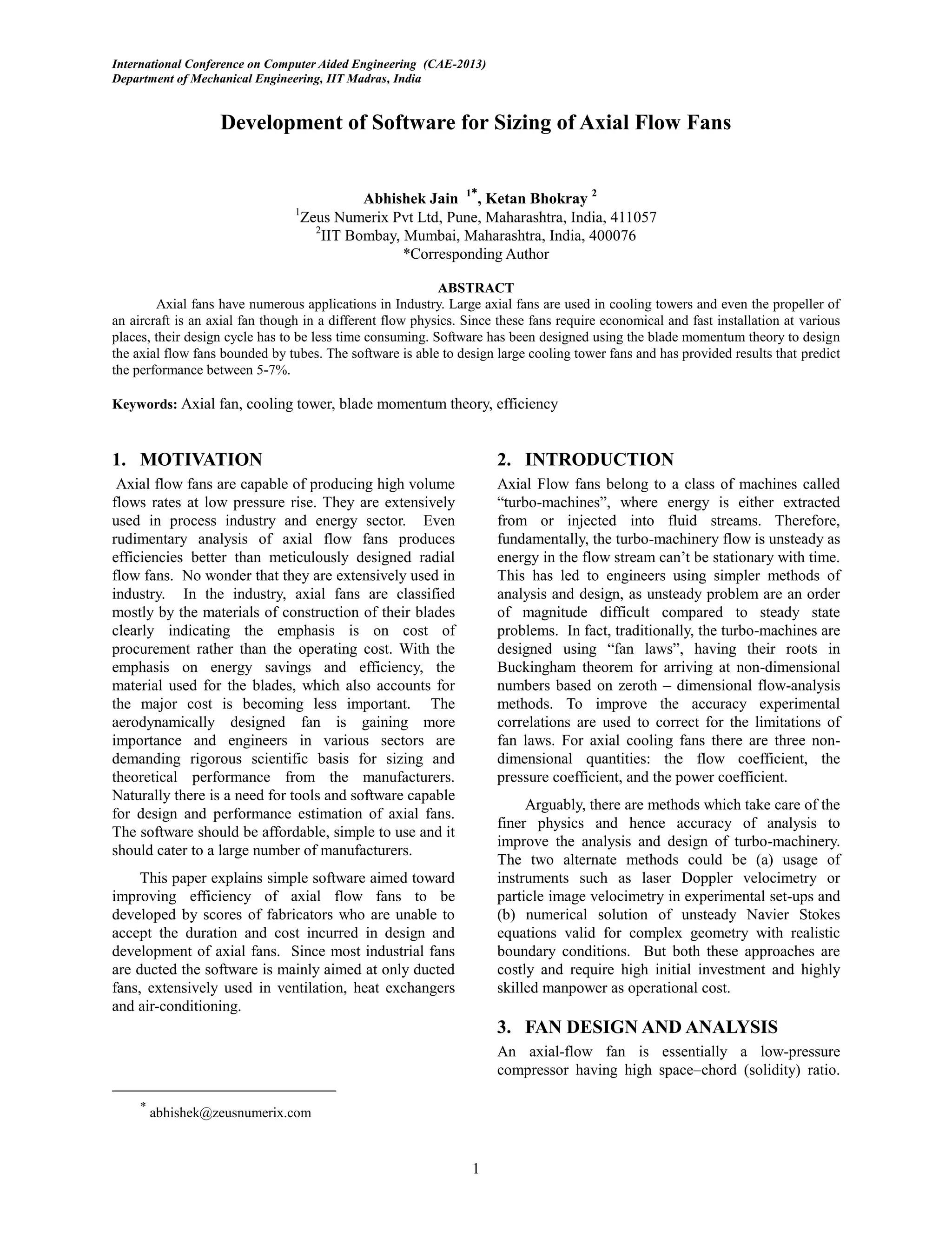
In blade element theory, it is assumed that fan
consists of blades of airfoil shaped cross sections of
varying chord but vanishingly small size compared to
the radius at the various radial locations as in Fig. 1.
The forces on the airfoil section are calculated as lift
and drag coefficients based aerodynamic
characteristics of the chosen airfoil section. The two
dimensional loads are integrated along the radius to
calculate the thrust and torque on the blades. These
quantities are multiplied by an integer equal to the
number of blades in the fan. Thrust on the all the
blades is divided by the area swept by the blades to get
the total pressure rise across the fan by conservation.
The novel feature of the methodology incorporated in
the code is the interference effects from adjacent
blades in modifying the lift curve slope of the airfoil
by a factor considered in detail by Wallis [2].
3.1. Equations
An airfoil section of a blade of length R , at radial
distance r from the hub of the fan and a thickness dr
as illustrated in Fig. 2, obtained from [3], is considered
for analysis
Fig. 2: The lateral view of an axial flow fan showing
different flow parameters.
is the geometric pitch angle of the cross section, is the
angle of attack the flow makes with this cross-section.
lift and drag are the force vectors normal to and tangential to
the cross section
thrust, torque/radius are forces perpendicular and parallel to
the surface of the fan.
0V and 2V are the magnitudes of the axial and tangential
velocities of the flow at the section, 1V being their resultant
The difference in angle between thrust and lift directions is
given by =
The density of the air is
The Velocities 0V and 2V are obtained from the Mass
Flow Rate m and the Flow Angular Velocity at the
section
20
.. R
m
V
(1)
RV .2 (2)
From the velocity vector triangle 0V , 1V and 2V
2
2
2
01 VVV (3)
2
0
tan
V
V
a (4)
From the force vector triangle, the torque/radius is
observed to be
)sin()cos( LDQ (5)
The flow angular velocity is then obtained from the
torque/radius
R
m
Q
.
(6)
Fig. 1: The blades of an axial flow fan are assumed
to be made of airfoil shaped cross sections with the
same airfoil throughout but different with chord
lengths at different radial positions](https://image.slidesharecdn.com/research-paper-on-development-of-software-for-sizing-of-axial-flow-fans-201118072932/75/Development-of-Software-for-Sizing-of-Axial-Flow-Fans-Zeus-Numerix-2-2048.jpg)
![Development of Software for Sizing of Axial Flow Fans
3
RVdrR
Q
...2 0
(7)
There now exists a nonlinear system of equations (1),
(2), (3), (4), (5), and (7) containing the primary
unknown variables Q , , , 2V and 1V . So, an
iterative solution to this system is possible by initially
substituting by the Fan Angular Velocity f . The
torque thus obtained is for a single section. The torque
on the whole blade is then obtained by adding the
elemental quantity and Q for all the sections.
4. RESULTS AND DISCUSSION
The software has been configured to: (1) Design of
high efficiency fan (2) Off-design analysis of a fan, (3)
Performance prediction of fan made of given blades.
For design the user requirements are to be known.
These are dictated usually by the space constraint,
amount of heat to be taken out, availability of pre-
manufactured components, manufacturability of airfoil
sections, availability of motor and gear ratios etc.
These constraints in turn technically decide (a) total
and hub diameter, (b) volume flow rate, (c) pressure
rise, (d) rpm, (e) airfoil section and (f) number of
blades (g) bounds of angle of attack.
The software has an automatic module for trying
various settings to arrive at the performance of the fan
for maximum efficiency. The fan can then be exported
to AutoCAD DXF file format in 3D and each section
to be provided directly to the manufacturing process.
Besides efficiency which is the main concern, the
software also provides the torque, thrust, power
required and the sound level.
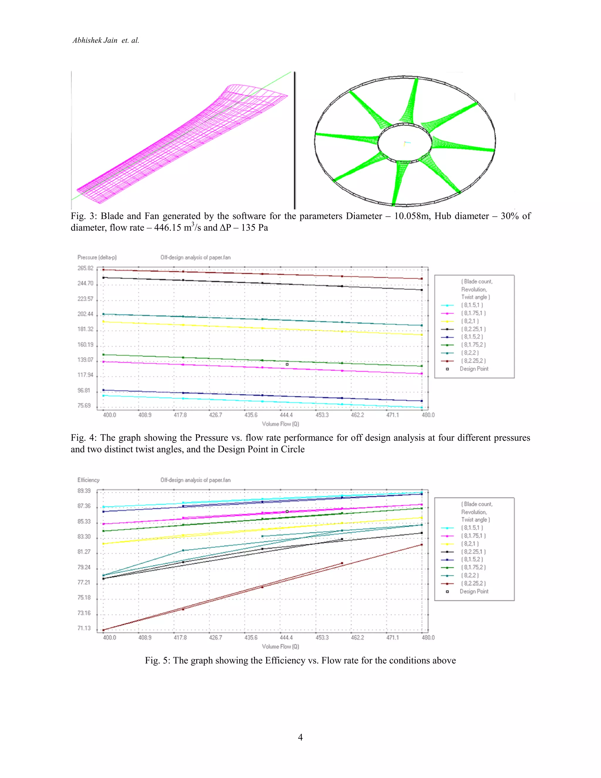
4.1. Fan Design
Cooling tower fan has been designed using the inputs
as given: Diameter – 10.058m, Hub diameter – 30% of
diameter, flow rate – 446.15 m3
/s and ΔP – 135 Pa. It
has been seen that 23012 airfoil is suitable for these
shapes and hence that same has been used to design the
fan. Maximum efficiency possible predicted has been
86.84%. In practice it has been seen that the results
have been consistently over predicted by 5-7% based
on the actual efficiency measured. It is important that
the over prediction is consistent and hence the designer
is in the know of actual efficiency. Fig. 3 shows the
blade of the fan and the fan that is generated for the
above case.
4.2. Off-design performance
Industry does not always have the same performance
requirement from the fan. Change in the heat load may
require significant alteration on the working of the fan
e.g. lower heat production may require the fan to
temporarily slow down. Performance of the fan in
these conditions has to be studied and the same has
been done for variation of various properties. The
design can be obtained for a variety of RPMs, flow
rates and a typical result is shown in Fig. 4. The graph
contains a pressure vs. flow rate for variation of five
flow rates, two additional twists and four different
rotational speeds. Fig. 5 shows the same for efficiency
vs. flow rate.
5. CONCLUSIONS
It is seen that the design of low speed axial fans with
cooling tower and other flow applications is possible.
The implemented procedure has been tested and the
manufactured fans show a predictable behavior
compared to the theoretical data. With the proving of
base codes it is advisable to extend the methodology to
other applications of axial flow such as small diameter
fans, propellers at high speed and possibly to radial
flow applications. No marked difference has been seen
with the variation of number of blades in the
performance of the fan. The same has been reported in
[4].
6. REFERENCES
[1] Ingram, Grant. "Wind Turbine Blade Analysis
using the Blade Element Momentum Method. Version
1.0." (2005): 1-21.
[2] Wallis, R. A., and F. I. E. Aust. "A Rationalized
Approach to Blade Element Design, Axial Flow Fans.
Institute of Engineers." Australia Conference on
Hydraulic and Fluid Mechanics. 1968.
[3] D.J, Auld, and Srinivas K. "Aerodynamics for
Students." Aerodynamics for Students. University of
Sydney, n.d. Web.
[4] “Basics of Axial flow Fans”, M0100-186 5M
W1/00, Hudson Product Corporation, 2000](https://image.slidesharecdn.com/research-paper-on-development-of-software-for-sizing-of-axial-flow-fans-201118072932/75/Development-of-Software-for-Sizing-of-Axial-Flow-Fans-Zeus-Numerix-3-2048.jpg)

The document discusses the development of software for designing axial flow fans, focusing on improved efficiency for industrial applications. It utilizes blade momentum theory to create a user-friendly tool that can rapidly design and analyze fan performance, particularly for ducted fans in cooling towers. The software achieves close performance predictions and enables customization based on user requirements, facilitating easier and more cost-effective manufacturing processes.


![examples_wwang[Turbo]](https://cdn.slidesharecdn.com/ss_thumbnails/1387eee9-474b-421c-9dba-322b0cd6afac-161004155700-thumbnail.jpg?width=640&height=640&fit=bounds)


