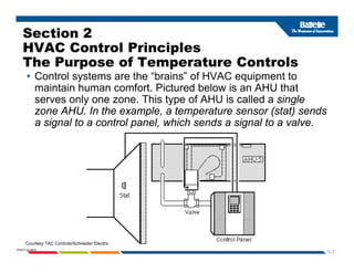
Automatic and DDC
Control Fundamentals
and Energy Conservation
for
HVAC Equipment-Part 1
1-1
Disclaimer
Disclaimer
This presentation was prepared specifically for use as
college training material It shall not be modified
college training material. It shall not be modified
without the consent of the authors.
This presentation represents sponsored research
activities. Neither the Client nor Battelle warrants
the accuracy, completeness or usefulness of the
information. Reference herein to any specific
i l d t i b t d
commercial product, process or service by trade
names or manufacturer does not constitute an
endorsement or recommendation.
1-2
PNWD-SA-8834
DDC Controls and Energy Conservation for
HVAC Eq ipment Agenda
HVAC Equipment - Agenda
1. Introduction of DDC Controls Project
2 HVAC C t l P i i l
2. HVAC Control Principles
3. Communication Standards and Networks
4 Vendor Examples of DDC Software Programming and
4. Vendor Examples of DDC Software Programming and
Operator Interfacing
5. Typical Rooftop and Central AHU HVAC Control
Systems and Applications
6. System Maintenance and Service of DDC Controls
7. Avoiding Common Control Problems and Fixing the
g g
Problems
8. Calibrating and Verifying Energy Savings of the DDC
Controls
1-3
PNWD-SA-8834
Part 1
HVAC Control Principles
1. Intent of Battelle Pacific NW Division involvement
2. Purpose of Controls
3. Key Components of Control Systems
y p y
4. Control Loops, Open vs. Closed Loops
5 Terminology
5. Terminology
6. The Control Cycle and Control Actions
7 Th E S f C t l S t
7. The Energy Sources for Control Systems
8. DDC Point Types
1-4
PNWD-SA-8834
Part 2
Control Applications, Networks,
Programming, Maintenance, and
Energy Savings
Energy Savings
1. DDC Control Applications
2. DDC Networks and Architecture
3. Communication Standards and Networks
4. Vendor Examples of DDC Software Programming
and Operator Interfacing
5. System maintenance and service of DDC controls
6. Using DDC controls to save energy
1-5
PNWD-SA-8834
g gy
Section 1
Introduction of DDC Controls Project
• Purpose of this project is to provide HVAC
d ti l t i l t W hi t St t
educational materials to Washington State
community colleges to educate students who have
chosen or may chose career paths related to HVAC
servicing and building energy management fields
1-6
PNWD-SA-8834
Section 2
HVAC Control Principles
The Purpose of Temperature Controls
• Control systems are the “brains” of HVAC equipment to
i t i h f t Pi t d b l i AHU th t
maintain human comfort. Pictured below is an AHU that
serves only one zone. This type of AHU is called a single
zone AHU. In the example, a temperature sensor (stat) sends
i l t t l l hi h d i l t l
a signal to a control panel, which sends a signal to a valve.
1-7
PNWD-SA-8834
Courtesy TAC Controls/Schneider Electric
Section 3
K C t f C t l
Key Components of a Control
System Include:
1-8
PNWD-SA-8834
Courtesy TAC Controls/Schneider Electric
Sensors
Modern HVAC Sensors Include:
• Humidity and temperature transmitters
• CO2 for indoor air quality (IAQ) utilizing
d d t l til ti
demand control ventilation
• Power meters
• Branch circuit monitors
• Energy meters
1-9
PNWD-SA-8834
Courtesy Veris Industries
Sensors
• A sensor monitors and measures a variable. The
HVAC variables are temperature, humidity, flow, and
pressure Different types of signals are produced by
pressure. Different types of signals are produced by
different types of sensors. They include:
–Electric sensors
Electric sensors
–Pneumatic sensors
Electronic sensors
–Electronic sensors
An example of a sensor is shown here. While it may
appear to be a thermostat, it is a remote sensor with
a remote setpoint dial The controller is in another
1-10
PNWD-SA-8834
a remote setpoint dial. The controller is in another
location. Courtesy TAC Controls/Schneider Electric
Pneumatic Sensors/Transmitters
• Pneumatic controls sensors or transmitters
sense the variable and produce a 3 psig to 15
psig (pound per square inch, gauge), [20 kPa
(kiloPascals) -105 kPa] signal over a particular
transmitter's range.
1-11
PNWD-SA-8834
Courtesy Johnson Controls
Electronic Sensors Include:
• Resistance sensors are resistance temperature
devices (RTDs) and are used in measuring
devices (RTDs), and are used in measuring
temperature. Examples are Balco elements, copper
platinum, 10K thermistors, and 30K thermistors.
• Voltage sensors could be used for temperature,
humidity and pressure. Typical ranges are 0 to 5
Vd (V lt di t t) 1 t 11 Vd d 0 t 10
Vdc (Volts direct current), 1 to 11 Vdc, and 0 to 10
Vdc.
C t ld b d f t t
• Current sensors could be used for temperature,
humidity, and pressure. The typical current range is
4 to 20 mA (milliamps).
1-12
PNWD-SA-8834
( p )
1000Ω (Ohms) Balco PTC
Electronic Temperature Sensors
• The resistance outputs of a electronic Balco temperature
sensor follow the diagrams below:
• When 1000 ohms is measured across the Balco element, the
temperature is approximately 70°F (21°C) As the temperature
temperature is approximately 70°F (21°C). As the temperature
increases, the resistance changes 2.2 ohms per 1°F (3.96
ohms per 1°C). In a Balco temperature sensor, as the
t t i th i t i ti ll
temperature increases, the resistance increases proportionally
in a positive direction. This is known as a positive temperature
coefficient (PTC) sensor. However, many temperature sensors
id d th i t d f N ti
1-13
PNWD-SA-8834
are considered thermistors, and perform as Negative
temperature coefficients (NTC).
Comparison of Common Temp Sensors
p p
1-14
PNWD-SA-8834
Courtesy Omega Controls
Controllers Can Include:
Electric Controls Pneumatic Controls
DDC
Controls
1-15
PNWD-SA-8834
Electronic Controls Courtesy Johnson, Honeywell, and Alerton Controls
Controllers basic principles
the controller receives the input
And processes an output
1-16
PNWD-SA-8834
Electronic Control System
y
1-17
PNWD-SA-8834
Courtesy Honeywell Controls
Pneumatic Controller System
“Branch” or Control Damper
Sensor
Branch or Control
Pressure
Damper
Sensor
Branch or Control
Pressure
Damper
Controller Operator
Filter
“Main” or Supply
Controller Operator
Filter
“Main” or Supply
Pressure
Regulator
pp y
Pressure
Compressor
Pressure
Regulator
pp y
Pressure
Compressor
Thermostat
Valve
Actuator Thermostat
Valve
Actuator
1-18
PNWD-SA-8834
Valve
Valve
Courtesy Northwest Energy Efficiency Council
The DDC controller receives the input
from the sensor, performs a logic
function and processes an output
function, and processes an output
1-19
PNWD-SA-8834
Courtesy DDC Online Org
Controller Action-Direct or Reverse
Illustration
1-20
PNWD-SA-8834
Courtesy Honeywell Controls
Controller Direct Action-Illustration
1-21
PNWD-SA-8834
Courtesy TAC Controls/Schneider Electric
Controller Direct Action-Illustration
• This relationship between the input to a controller
(temperature) and its output (current) can be
displayed on a graph as follows:
1-22
PNWD-SA-8834
Courtesy TAC Controls/Schneider Electric
Controller Reverse Action-Illustration
Controller Reverse Action Illustration
1-23
PNWD-SA-8834
Courtesy TAC Controls/Schneider Electric
Controller Reverse Action-Illustration
Controller Reverse Action Illustration
• This relationship can is displayed on a graph as
follows:
follows:
1-24
PNWD-SA-8834
Courtesy TAC Controls/Schneider Electric
Controlled Devices
Controlled Devices
Control Valves
Control Valves
– two-way Control Valves
Used with differential pressure (DP) sensors and VSD pump
systems on primary and secondary loops
– three-way (mixing or diverting)
Press re independent control al es
– Pressure independent control valves
Automatic dampers
Automatic dampers
Damper operators
VSDs: variable speed drives
1-25
PNWD-SA-8834
VSDs: variable speed drives
Courtesy Belimo
Controlled Devices
Valves
Mixing Valve
Diverting Valve
g
T i l Th W Mi i
1-26
PNWD-SA-8834
Typical Three-Way Mixing
and Diverting Valves
Typical Single - and Double-Seated
Two-Way Valves
Courtesy Belimo
The Present Control Systems
•Pressure independent control valves
y
Use control valves that are:
Pressure independent control valves
•No Cv required, reduced pumping costs, higher
efficiency, easy to balance.
1-27
PNWD-SA-8834
Courtesy Flow Control Valves
Examples of 2-Way and 3-Way
Control Valves
1-28
PNWD-SA-8834
Northwest Energy Efficiency Council
Dampers: Types, Actuators,
and Characteristics
and Characteristics
– Economizers on many central AHUs are
custom ordered for the job specific
custo o de ed o t e job spec c
requirements
– Economizers on packaged RTUs are
normally ordered as an option with the
package
– Control Dampers Can Be Either:
P ll l d d
Parallel or opposed dampers
1-29
PNWD-SA-8834
Parallel Blade Opposed Blade
Economizer Damper Actuator Types
are either:
Electric Electronic
Pneumatic Electric Electronic
Pneumatic
1-30
PNWD-SA-8834
Economizer Damper Actuators
will have either direct connect actuators bolted
directly to the damper or they will be installed with a
shaft and linkage arrangement (more prone to fail)
1-31
PNWD-SA-8834
Direct Connect Actuator Damper Connected to Actuator
Via Shaft and Coupling
Parallel Blade Damper Characteristics
have poor linear control
p
1-32
PNWD-SA-8834
Courtesy T.A. & Co.
Opposed Damper Characteristics
have better linear control
1-33
PNWD-SA-8834
Courtesy T.A. & Co.
Damper Actuators can be Controlled by :
p y
• Voltage (0-10Vdc or 2-10Vdc)
• Current (4-20mA)
Fl ti i t (bi l t l )
• Floating point (binary pulse to open or close)
• PWM-pulse width modulated
• Resistance (0-135 ohms)
Resistance (0 135 ohms)
1-34
PNWD-SA-8834
Example of analog control using 4-20mA or 2-10Vdc
Courtesy Belimo
Electronic Variable
F D i (VSD )
Frequency Drives (VSDs)
•Vary frequency of motor to control speed
•Often called VSDs VFDs or ASDs
•Often called VSDs, VFDs, or ASDs
1-35
PNWD-SA-8834
DDC control systems have variable
f ( )
frequency drives (VFDs) as
standard equipment on:
C li
• Cooling towers
• AHU’s and VAV fans
• Pumps
• Chillers
1-36
PNWD-SA-8834
Variable Speed Drives
1-37
PNWD-SA-8834
Courtesy ABB Controls
Review of the Key Control
Components
Components
Exercise-identify the sensors, controllers, and
controlled devices
1-38
PNWD-SA-8834
Courtesy TAC Controls/Schneider Electric
Review of the Key Control
y
Components
Exercise-connect the sensor, controller, and
controlled device in the proper order
controlled device in the proper order.
1-39
PNWD-SA-8834
Courtesy Alerton and Belimo
Review of Control Action
Exercise the control drawing below has a
Exercise-the control drawing below has a
direct acting controller, with a NO valve. Show
the correct action with arrows at each
t h d f li d
component when used for cooling mode.
___________Acting
1-40
PNWD-SA-8834
Courtesy TAC Controls/Schneider Electric and Belimo
Review of Control Action
Exercise-Circle the correct answer.
1-41
PNWD-SA-8834
Courtesy TAC Controls/Schneider Electric
Review of Control Action
Exercise Circle the correct answer
Exercise-Circle the correct answer.
1-42
PNWD-SA-8834
Courtesy TAC Controls/Schneider Electric
Review of Control Action
Exercise-Circle the correct answer.
1-43
PNWD-SA-8834
Courtesy TAC Controls/Schneider Electric
Review of the Key Control
Components
Components
Exercise-Identify the parallel vs. opposed blade
dampers and the 3-way mixing vs. diverting
1-44
PNWD-SA-8834
Courtesy Belimo
_________________
_________________ _________________
_________________
Section 4
Section 4
Basic Control Loop Principles
Controllers can be either
“ l d” “ ” L
Cl l id f db k d l
“closed” or “open” Loop
–Closes loops provide feedback-good control
–Open loops have no feedback-poor control
1-45
PNWD-SA-8834
Basic Closed-Loop-Example
The sensor feeds back to the controller
1-46
PNWD-SA-8834
Courtesy DDC Online Org
Open Loop Controls
have no feedback to the controller
1-47
PNWD-SA-8834
Courtesy DDC Online Org
Closed vs. Open Loop Control
Illustration
Notice, averaging bulb is closed loop in supply air,
but T-STAT between filter and coil is open loop.
1-48
PNWD-SA-8834
Courtesy Northwest Energy Efficiency Council
Section 5
Control Terminology
Setpoint, offset, and control point
Throttling range
Span and range
p g
Authority
Calibration
Analog and digital
Thermostat as sensor-controller
1-49
PNWD-SA-8834
Setpoint
Setpoint is the desired condition of a variable that is to be
maintained, such as temperature. In the example below,
75 degrees F is the room temperature setpoint that the
75 degrees F. is the room temperature setpoint that the
building occupant desires.
1-50
PNWD-SA-8834
Courtesy TAC Controls/Schneider Electric
Control Point and Offset
• The Control point is the actual temperature being sensed.
The control point (temperature) may not be on the setpoint,
but instead may be above or below it. Simply stated,
setpoint is what you want, while control point is what you
get. Offset is the amount of difference between control
point and setpoint in a proportional control system In the
point and setpoint in a proportional control system. In the
example below, the offset is approximately 4°F.
1-51
PNWD-SA-8834
Courtesy TAC Controls/Schneider Electric
Throttling Range
g g
• System throttling range (STR) is the change in the
measured variable (i e temperature) that causes
measured variable (i.e., temperature) that causes
the controlled device to travel from one end of its
stroke to the other.
1-52
PNWD-SA-8834
Courtesy TAC Controls/Schneider Electric
Section 6
T iti
The Control Cycle and Control Action
•Two position
•Floating action
•Proportional action
•PI
PI
•PID
1-53
PNWD-SA-8834
Courtesy PECI
Control Cycle Graph
1-54
PNWD-SA-8834
Courtesy Northwest Energy Efficiency Council
T P iti C t l
Two Position Control
1-55
PNWD-SA-8834
Two Position control action chart (heating action shown)
Courtesy Northwest Energy Efficiency Council
T P iti C t l R
Two Position Control Response
1-56
PNWD-SA-8834
Floating Action Control
1-57
PNWD-SA-8834
Courtesy Northwest Energy Efficiency Council
P ti l C t l A ti
Proportional Control Action
1-58
PNWD-SA-8834
Courtesy Northwest Energy Efficiency Council
Proportional with
I t l C t l (PI)
Integral Control (PI)
Proportional Plus Integral (PI) Control Action
1-59
PNWD-SA-8834
Courtesy Northwest Energy Efficiency Council
PID-Proportional
p
Plus Integral & Derivative
Proportional Plus Integral Plus Derivative (PID) control action
1-60
PNWD-SA-8834
Proportional Plus Integral Plus Derivative (PID) control action
Courtesy Northwest Energy Efficiency Council
Adaptive Control
Adaptive loop tuning provides:
•Accurate, continuous loop control
•Faster tuning of loops for energy savings
•Less wear on valves, actuators, fans, pumps, dampers,
VFDs, etc.
VFDs, etc.
1-61
PNWD-SA-8834
Review of Control Cycles
Exercise; study the drawings and identify
the control loop types as either:
2-position, proportional, or PI Control
_________________
1-62
PNWD-SA-8834
_________________
_________________
Courtesy Northwest Energy Efficiency Council
Review of Control Cycles
Exercise; identify and circle the closed
loop vs. the open loop controls.
1-63
PNWD-SA-8834
Courtesy Northwest Energy Efficiency Council
Review of Control Cycles
y
Exercise; review the drawing and
identify setpoint, control point, TR,
and offset
and offset.
1-64
PNWD-SA-8834
Courtesy TAC Controls/Schneider Electric
Review of DDC Terminology
Exercise; identify the missing terms
1-65
PNWD-SA-8834
Courtesy Northwest Energy Efficiency Council
Section 7
Control Energy Sources
A power supply or source of energy is needed to
power the control system Control systems use
power the control system. Control systems use
either a pneumatic or electric power supply.
• Pneumatic controls use a compressed gas as a
Pneumatic controls use a compressed gas as a
source of energy, typically compressed air.
• Electric and electronic controls could be
Electric and electronic controls could be
powered by a variety of electrical power supplies
of either alternating current (AC) or direct current
(DC)
(DC).
• DDC-Direct digital controls are considered
electronically powered via a network of controls
1-66
PNWD-SA-8834
electronically powered via a network of controls.
Comparing Advantages
And Disadvantages
And Disadvantages
of pneumatics and DDC controls
•Pneumatic control systems
•Low maintenance, ease of testing
•Hard to integrate into DDC systems
•Requires air compressor station
DDC Di t di it l t l
•DDC – Direct digital control
•High accuracy
•Flexible easy to access
•Flexible, easy to access
•Programmable
•Energy management considerations
1-67
PNWD-SA-8834
•Energy management considerations
•Easy to optimize, reduce kW peaks, schedule
Basic Pneumatic Control System
The Air Station Components
1-68
PNWD-SA-8834
Courtesy Honeywell Controls
Basic Pneumatic Control System
1-69
PNWD-SA-8834
Conventional Pneumatic
Control Systems
Requirements:
Clean and dry air supply
■ Clean and dry air supply
■ Pressure reducing valve
■ Utilizes pneumatic controllers
■ Pneumatic devices
1-70
PNWD-SA-8834
Pneumatic Controls Include:
• Thermostats that can be either:
Pneumatic Controls Include:
Thermostats that can be either:
• Room type
• Dead band types
yp
• Dual pressure type
• Humidistats
• Receiver controllers
• Combine 2 sensors into 1 receiver with reset
setpoint options
• Utilizes either one pipe or two pipes
Sensors
1-71
PNWD-SA-8834
• Sensors
Pneumatic Control of Heating
Coil Control with Reset
1-72
PNWD-SA-8834
Courtesy Northwest Energy Efficiency Council
Pneumatic Control System
Accessories
Accessories
Pneumatic relays:
■ Reversing relay
■ Reversing relay
■ High/low pressure selector
■ Air motion
■ Signal repeating
Pneumatic Switch
■ Signal repeating
■ Minimum position
EP-Electric to Pressure Switch
1-73
PNWD-SA-8834
■ EPs and PEs PE-Pressure to Electric Switch
B i P ti C t l S t
Basic Pneumatic Control System
1-74
PNWD-SA-8834
Example of Pneumatic Controls
1-75
PNWD-SA-8834
Courtesy LAMA Books
Basic Electric Control
1-76
PNWD-SA-8834
Courtesy Honeywell Controls
Example of Electric Controls
a p e o ect c Co t o s
for Economizers
1-77
PNWD-SA-8834
Courtesy Honeywell Controls
Simple Electronic Control
S t
System
1-78
PNWD-SA-8834
Courtesy Honeywell Controls
Example of Electronic Control for
Basic AHU Economizer Control
1-79
PNWD-SA-8834
Courtesy Honeywell Controls
Example of Electronic Control for
Economizers with Differential Enthalpy
and CO2 Demand Ventilation Control
1-80
PNWD-SA-8834
Courtesy Honeywell Controls
Section 8-DDC Point Types
Input and Output Point Types Chart
p p yp
Input Output
Di it l
Two state information from the building
into the DDC field panel
Two state information from DDC field
panel to the building
Digital
Switches: On/Off - fans, pumps, lights
Differential press/proof Open/Close, two position damper
Smoke alarms Control of two-speed motors
Smoke alarms Control of two speed motors
Level alarm Energize/de-energize valves for
heat/cool changeovers
High/low pressure alarm
Filter status
Filter status
Analog
Variable information from the building
into the DDC control panel
Variable information from the DDC
control panel out to the building
Temperature Room duct OSA Modulate valves dampers actuators
Temperature-Room, duct, OSA Modulate valves, dampers, actuators
Humidities-Room, duct, OSA Motor speed control – VSDs
Pressure-Static, velocity, total Modulate volume dampers
1-81
PNWD-SA-8834
Flow rates-Water and air systems Adjust air pressure to pressure operated
devices
kWh power, volts, and amps
DDC Control System
Digital Input (DI) Illustration
1-82
PNWD-SA-8834
Courtesy DDC Online Org.
DDC Control System
Digital Input (DI) Illustration
Flow Switch
1-83
PNWD-SA-8834
Courtesy Honeywell Controls
DDC Control System
Digital Input (DI) Pulsed Signal
Illustration
Flow Switch
1-84
PNWD-SA-8834
Courtesy Verris Industries
DDC Control System
Digital Output (DO) Illustration
Transistor with Pilot Relay
Triac Type Digital Output with External Relay
1-85
PNWD-SA-8834
Courtesy DDC Online Org.
DDC Control System
A l I t (AI) Ill t ti
Analog Input (AI) Illustration
1-86
PNWD-SA-8834
Courtesy DDC Online Org.
DDC Control System
Analog Input (AI) Illustration
For Measuring Air Flow in FPM
g
1-87
PNWD-SA-8834
Courtesy Dwyer Instruments.
DDC Control System
Analog Output (AO) Illustration
For controlling a pneumatic valve
g p
1-88
PNWD-SA-8834
Courtesy TAC Controls/Schneider Electric
Analog Output (AO) Damper Actuators
g p ( ) p
are controlled by either a voltage (2-10 Vdc) or
current (4-20 mA) signal from the controller
1-89
PNWD-SA-8834
Courtesy Belimo
Example of DDC AHU Control
p
Application with Point Types Identified
1-90
PNWD-SA-8834
Courtesy Honeywell Controls.
Exercise
Review of DDC Terminology
1-91
PNWD-SA-8834
Courtesy TAC Controls/Schneider Electric
Exercise
Review of DDC Terminology
1-92
PNWD-SA-8834
Courtesy TAC Controls/Schneider Electric

ddc_controls_part_1_pnwd-sa-883dddds4.pdf

  • 1.
    Automatic and DDC ControlFundamentals and Energy Conservation for HVAC Equipment-Part 1 1-1
  • 2.
    Disclaimer Disclaimer This presentation wasprepared specifically for use as college training material It shall not be modified college training material. It shall not be modified without the consent of the authors. This presentation represents sponsored research activities. Neither the Client nor Battelle warrants activities. Neither the Client nor Battelle warrants the accuracy, completeness or usefulness of the information. Reference herein to any specific i l d t i b t d commercial product, process or service by trade names or manufacturer does not constitute an endorsement or recommendation. 1-2 PNWD-SA-8834
  • 3.
    DDC Controls andEnergy Conservation for HVAC Eq ipment Agenda HVAC Equipment - Agenda 1. Introduction of DDC Controls Project 2 HVAC C t l P i i l 2. HVAC Control Principles 3. Communication Standards and Networks 4 Vendor Examples of DDC Software Programming and 4. Vendor Examples of DDC Software Programming and Operator Interfacing 5. Typical Rooftop and Central AHU HVAC Control Systems and Applications Systems and Applications 6. System Maintenance and Service of DDC Controls 7. Avoiding Common Control Problems and Fixing the g g Problems 8. Calibrating and Verifying Energy Savings of the DDC Controls 1-3 PNWD-SA-8834
  • 4.
    Part 1 HVAC ControlPrinciples HVAC Control Principles 1. Intent of Battelle Pacific NW Division involvement 2. Purpose of Controls 3. Key Components of Control Systems y p y 4. Control Loops, Open vs. Closed Loops 5 Terminology 5. Terminology 6. The Control Cycle and Control Actions 7 Th E S f C t l S t 7. The Energy Sources for Control Systems 8. DDC Point Types 1-4 PNWD-SA-8834
  • 5.
    Part 2 Control Applications,Networks, Programming, Maintenance, and Energy Savings Energy Savings 1. DDC Control Applications 2. DDC Networks and Architecture 3. Communication Standards and Networks 4. Vendor Examples of DDC Software Programming and Operator Interfacing 5. System maintenance and service of DDC controls 6. Using DDC controls to save energy 1-5 PNWD-SA-8834 g gy
  • 6.
    Section 1 Introduction ofDDC Controls Project • Purpose of this project is to provide HVAC d ti l t i l t W hi t St t educational materials to Washington State community colleges to educate students who have chosen or may chose career paths related to HVAC chosen or may chose career paths related to HVAC servicing and building energy management fields 1-6 PNWD-SA-8834
  • 7.
    Section 2 HVAC ControlPrinciples HVAC Control Principles The Purpose of Temperature Controls • Control systems are the “brains” of HVAC equipment to i t i h f t Pi t d b l i AHU th t maintain human comfort. Pictured below is an AHU that serves only one zone. This type of AHU is called a single zone AHU. In the example, a temperature sensor (stat) sends i l t t l l hi h d i l t l a signal to a control panel, which sends a signal to a valve. 1-7 PNWD-SA-8834 Courtesy TAC Controls/Schneider Electric
  • 8.
    Section 3 K Ct f C t l Key Components of a Control System Include: 1-8 PNWD-SA-8834 Courtesy TAC Controls/Schneider Electric
  • 9.
    Sensors Modern HVAC SensorsInclude: • Humidity and temperature transmitters • CO2 for indoor air quality (IAQ) utilizing d d t l til ti demand control ventilation • Power meters • Branch circuit monitors • Branch circuit monitors • Energy meters 1-9 PNWD-SA-8834 Courtesy Veris Industries
  • 10.
    Sensors • A sensormonitors and measures a variable. The HVAC variables are temperature, humidity, flow, and pressure Different types of signals are produced by pressure. Different types of signals are produced by different types of sensors. They include: –Electric sensors Electric sensors –Pneumatic sensors Electronic sensors –Electronic sensors An example of a sensor is shown here. While it may appear to be a thermostat, it is a remote sensor with a remote setpoint dial The controller is in another 1-10 PNWD-SA-8834 a remote setpoint dial. The controller is in another location. Courtesy TAC Controls/Schneider Electric
  • 11.
    Pneumatic Sensors/Transmitters • Pneumaticcontrols sensors or transmitters sense the variable and produce a 3 psig to 15 sense the variable and produce a 3 psig to 15 psig (pound per square inch, gauge), [20 kPa (kiloPascals) -105 kPa] signal over a particular transmitter's range. 1-11 PNWD-SA-8834 Courtesy Johnson Controls
  • 12.
    Electronic Sensors Include: •Resistance sensors are resistance temperature devices (RTDs) and are used in measuring devices (RTDs), and are used in measuring temperature. Examples are Balco elements, copper platinum, 10K thermistors, and 30K thermistors. • Voltage sensors could be used for temperature, humidity and pressure. Typical ranges are 0 to 5 Vd (V lt di t t) 1 t 11 Vd d 0 t 10 Vdc (Volts direct current), 1 to 11 Vdc, and 0 to 10 Vdc. C t ld b d f t t • Current sensors could be used for temperature, humidity, and pressure. The typical current range is 4 to 20 mA (milliamps). 1-12 PNWD-SA-8834 ( p )
  • 13.
    1000Ω (Ohms) BalcoPTC Electronic Temperature Sensors Electronic Temperature Sensors • The resistance outputs of a electronic Balco temperature sensor follow the diagrams below: • When 1000 ohms is measured across the Balco element, the temperature is approximately 70°F (21°C) As the temperature temperature is approximately 70°F (21°C). As the temperature increases, the resistance changes 2.2 ohms per 1°F (3.96 ohms per 1°C). In a Balco temperature sensor, as the t t i th i t i ti ll temperature increases, the resistance increases proportionally in a positive direction. This is known as a positive temperature coefficient (PTC) sensor. However, many temperature sensors id d th i t d f N ti 1-13 PNWD-SA-8834 are considered thermistors, and perform as Negative temperature coefficients (NTC).
  • 14.
    Comparison of CommonTemp Sensors p p 1-14 PNWD-SA-8834 Courtesy Omega Controls
  • 15.
    Controllers Can Include: ElectricControls Pneumatic Controls DDC Controls 1-15 PNWD-SA-8834 Electronic Controls Courtesy Johnson, Honeywell, and Alerton Controls
  • 16.
    Controllers basic principles thecontroller receives the input And processes an output 1-16 PNWD-SA-8834
  • 17.
  • 18.
    Pneumatic Controller System PneumaticController System “Branch” or Control Damper “Branch” or Control Damper Sensor Branch or Control Pressure Damper Sensor Branch or Control Pressure Damper Controller Operator Filter “Main” or Supply Controller Operator Filter “Main” or Supply Pressure Regulator pp y Pressure Compressor Pressure Regulator pp y Pressure Compressor Thermostat Valve Actuator Thermostat Valve Actuator 1-18 PNWD-SA-8834 Valve Valve Courtesy Northwest Energy Efficiency Council
  • 19.
    The DDC controllerreceives the input The DDC controller receives the input from the sensor, performs a logic function and processes an output function, and processes an output 1-19 PNWD-SA-8834 Courtesy DDC Online Org
  • 20.
    Controller Action-Direct orReverse Illustration 1-20 PNWD-SA-8834 Courtesy Honeywell Controls
  • 21.
  • 22.
    Controller Direct Action-Illustration •This relationship between the input to a controller (temperature) and its output (current) can be (temperature) and its output (current) can be displayed on a graph as follows: 1-22 PNWD-SA-8834 Courtesy TAC Controls/Schneider Electric
  • 23.
    Controller Reverse Action-Illustration ControllerReverse Action Illustration 1-23 PNWD-SA-8834 Courtesy TAC Controls/Schneider Electric
  • 24.
    Controller Reverse Action-Illustration ControllerReverse Action Illustration • This relationship can is displayed on a graph as follows: follows: 1-24 PNWD-SA-8834 Courtesy TAC Controls/Schneider Electric
  • 25.
    Controlled Devices Controlled Devices ControlValves Control Valves – two-way Control Valves Used with differential pressure (DP) sensors and VSD pump systems on primary and secondary loops – three-way (mixing or diverting) Press re independent control al es – Pressure independent control valves Automatic dampers Automatic dampers Damper operators VSDs: variable speed drives 1-25 PNWD-SA-8834 VSDs: variable speed drives Courtesy Belimo
  • 26.
    Controlled Devices Valves Mixing Valve DivertingValve g T i l Th W Mi i 1-26 PNWD-SA-8834 Typical Three-Way Mixing and Diverting Valves Typical Single - and Double-Seated Two-Way Valves Courtesy Belimo
  • 27.
    The Present ControlSystems •Pressure independent control valves y Use control valves that are: Pressure independent control valves •No Cv required, reduced pumping costs, higher efficiency, easy to balance. 1-27 PNWD-SA-8834 Courtesy Flow Control Valves
  • 28.
    Examples of 2-Wayand 3-Way Control Valves 1-28 PNWD-SA-8834 Northwest Energy Efficiency Council
  • 29.
    Dampers: Types, Actuators, andCharacteristics and Characteristics – Economizers on many central AHUs are custom ordered for the job specific custo o de ed o t e job spec c requirements – Economizers on packaged RTUs are normally ordered as an option with the normally ordered as an option with the package – Control Dampers Can Be Either: P ll l d d Parallel or opposed dampers 1-29 PNWD-SA-8834 Parallel Blade Opposed Blade
  • 30.
    Economizer Damper ActuatorTypes are either: Electric Electronic Pneumatic Electric Electronic Pneumatic 1-30 PNWD-SA-8834
  • 31.
    Economizer Damper Actuators willhave either direct connect actuators bolted will have either direct connect actuators bolted directly to the damper or they will be installed with a shaft and linkage arrangement (more prone to fail) 1-31 PNWD-SA-8834 Direct Connect Actuator Damper Connected to Actuator Via Shaft and Coupling
  • 32.
    Parallel Blade DamperCharacteristics have poor linear control p 1-32 PNWD-SA-8834 Courtesy T.A. & Co.
  • 33.
    Opposed Damper Characteristics havebetter linear control 1-33 PNWD-SA-8834 Courtesy T.A. & Co.
  • 34.
    Damper Actuators canbe Controlled by : p y • Voltage (0-10Vdc or 2-10Vdc) • Current (4-20mA) Fl ti i t (bi l t l ) • Floating point (binary pulse to open or close) • PWM-pulse width modulated • Resistance (0-135 ohms) Resistance (0 135 ohms) 1-34 PNWD-SA-8834 Example of analog control using 4-20mA or 2-10Vdc Courtesy Belimo
  • 35.
    Electronic Variable F Di (VSD ) Frequency Drives (VSDs) •Vary frequency of motor to control speed •Often called VSDs VFDs or ASDs •Often called VSDs, VFDs, or ASDs 1-35 PNWD-SA-8834
  • 36.
    DDC control systemshave variable f ( ) frequency drives (VFDs) as standard equipment on: C li • Cooling towers • AHU’s and VAV fans • Pumps • Chillers 1-36 PNWD-SA-8834
  • 37.
    Variable Speed Drives VariableSpeed Drives 1-37 PNWD-SA-8834 Courtesy ABB Controls
  • 38.
    Review of theKey Control Components Components Exercise-identify the sensors, controllers, and controlled devices 1-38 PNWD-SA-8834 Courtesy TAC Controls/Schneider Electric
  • 39.
    Review of theKey Control y Components Exercise-connect the sensor, controller, and controlled device in the proper order controlled device in the proper order. 1-39 PNWD-SA-8834 Courtesy Alerton and Belimo
  • 40.
    Review of ControlAction Exercise the control drawing below has a Exercise-the control drawing below has a direct acting controller, with a NO valve. Show the correct action with arrows at each t h d f li d component when used for cooling mode. ___________Acting 1-40 PNWD-SA-8834 Courtesy TAC Controls/Schneider Electric and Belimo
  • 41.
    Review of ControlAction Exercise-Circle the correct answer. 1-41 PNWD-SA-8834 Courtesy TAC Controls/Schneider Electric
  • 42.
    Review of ControlAction Exercise Circle the correct answer Exercise-Circle the correct answer. 1-42 PNWD-SA-8834 Courtesy TAC Controls/Schneider Electric
  • 43.
    Review of ControlAction Exercise-Circle the correct answer. 1-43 PNWD-SA-8834 Courtesy TAC Controls/Schneider Electric
  • 44.
    Review of theKey Control Components Components Exercise-Identify the parallel vs. opposed blade dampers and the 3-way mixing vs. diverting 1-44 PNWD-SA-8834 Courtesy Belimo _________________ _________________ _________________ _________________
  • 45.
    Section 4 Section 4 BasicControl Loop Principles Controllers can be either “ l d” “ ” L Cl l id f db k d l “closed” or “open” Loop –Closes loops provide feedback-good control –Open loops have no feedback-poor control 1-45 PNWD-SA-8834
  • 46.
    Basic Closed-Loop-Example The sensorfeeds back to the controller 1-46 PNWD-SA-8834 Courtesy DDC Online Org
  • 47.
    Open Loop Controls haveno feedback to the controller 1-47 PNWD-SA-8834 Courtesy DDC Online Org
  • 48.
    Closed vs. OpenLoop Control Illustration Notice, averaging bulb is closed loop in supply air, but T-STAT between filter and coil is open loop. 1-48 PNWD-SA-8834 Courtesy Northwest Energy Efficiency Council
  • 49.
    Section 5 Control Terminology Setpoint,offset, and control point Setpoint, offset, and control point Throttling range Span and range p g Authority Calibration Analog and digital Thermostat as sensor-controller 1-49 PNWD-SA-8834
  • 50.
    Setpoint Setpoint is thedesired condition of a variable that is to be maintained, such as temperature. In the example below, 75 degrees F is the room temperature setpoint that the 75 degrees F. is the room temperature setpoint that the building occupant desires. 1-50 PNWD-SA-8834 Courtesy TAC Controls/Schneider Electric
  • 51.
    Control Point andOffset • The Control point is the actual temperature being sensed. The control point (temperature) may not be on the setpoint, but instead may be above or below it. Simply stated, but instead may be above or below it. Simply stated, setpoint is what you want, while control point is what you get. Offset is the amount of difference between control point and setpoint in a proportional control system In the point and setpoint in a proportional control system. In the example below, the offset is approximately 4°F. 1-51 PNWD-SA-8834 Courtesy TAC Controls/Schneider Electric
  • 52.
    Throttling Range g g •System throttling range (STR) is the change in the measured variable (i e temperature) that causes measured variable (i.e., temperature) that causes the controlled device to travel from one end of its stroke to the other. 1-52 PNWD-SA-8834 Courtesy TAC Controls/Schneider Electric
  • 53.
    Section 6 T iti TheControl Cycle and Control Action •Two position •Floating action •Proportional action •PI PI •PID 1-53 PNWD-SA-8834 Courtesy PECI
  • 54.
    Control Cycle Graph 1-54 PNWD-SA-8834 CourtesyNorthwest Energy Efficiency Council
  • 55.
    T P itiC t l Two Position Control 1-55 PNWD-SA-8834 Two Position control action chart (heating action shown) Courtesy Northwest Energy Efficiency Council
  • 56.
    T P itiC t l R Two Position Control Response 1-56 PNWD-SA-8834
  • 57.
    Floating Action Control FloatingAction Control 1-57 PNWD-SA-8834 Courtesy Northwest Energy Efficiency Council
  • 58.
    P ti lC t l A ti Proportional Control Action Proportional Control Action 1-58 PNWD-SA-8834 Courtesy Northwest Energy Efficiency Council
  • 59.
    Proportional with I tl C t l (PI) Integral Control (PI) Proportional Plus Integral (PI) Control Action 1-59 PNWD-SA-8834 Courtesy Northwest Energy Efficiency Council
  • 60.
    PID-Proportional p Plus Integral &Derivative Proportional Plus Integral Plus Derivative (PID) control action 1-60 PNWD-SA-8834 Proportional Plus Integral Plus Derivative (PID) control action Courtesy Northwest Energy Efficiency Council
  • 61.
    Adaptive Control Adaptive looptuning provides: •Accurate, continuous loop control •Faster tuning of loops for energy savings •Less wear on valves, actuators, fans, pumps, dampers, VFDs, etc. VFDs, etc. 1-61 PNWD-SA-8834
  • 62.
    Review of ControlCycles Exercise; study the drawings and identify Exercise; study the drawings and identify the control loop types as either: 2-position, proportional, or PI Control _________________ 1-62 PNWD-SA-8834 _________________ _________________ Courtesy Northwest Energy Efficiency Council
  • 63.
    Review of ControlCycles Exercise; identify and circle the closed Exercise; identify and circle the closed loop vs. the open loop controls. 1-63 PNWD-SA-8834 Courtesy Northwest Energy Efficiency Council
  • 64.
    Review of ControlCycles y Exercise; review the drawing and identify setpoint, control point, TR, and offset and offset. 1-64 PNWD-SA-8834 Courtesy TAC Controls/Schneider Electric
  • 65.
    Review of DDCTerminology Exercise; identify the missing terms Exercise; identify the missing terms 1-65 PNWD-SA-8834 Courtesy Northwest Energy Efficiency Council
  • 66.
    Section 7 Control EnergySources Control Energy Sources A power supply or source of energy is needed to power the control system Control systems use power the control system. Control systems use either a pneumatic or electric power supply. • Pneumatic controls use a compressed gas as a Pneumatic controls use a compressed gas as a source of energy, typically compressed air. • Electric and electronic controls could be Electric and electronic controls could be powered by a variety of electrical power supplies of either alternating current (AC) or direct current (DC) (DC). • DDC-Direct digital controls are considered electronically powered via a network of controls 1-66 PNWD-SA-8834 electronically powered via a network of controls.
  • 67.
    Comparing Advantages And Disadvantages AndDisadvantages of pneumatics and DDC controls •Pneumatic control systems •Low maintenance, ease of testing •Hard to integrate into DDC systems •Requires air compressor station DDC Di t di it l t l •DDC – Direct digital control •High accuracy •Flexible easy to access •Flexible, easy to access •Programmable •Energy management considerations 1-67 PNWD-SA-8834 •Energy management considerations •Easy to optimize, reduce kW peaks, schedule
  • 68.
    Basic Pneumatic ControlSystem Basic Pneumatic Control System The Air Station Components 1-68 PNWD-SA-8834 Courtesy Honeywell Controls
  • 69.
    Basic Pneumatic ControlSystem Basic Pneumatic Control System 1-69 PNWD-SA-8834
  • 70.
    Conventional Pneumatic Control Systems Requirements: Cleanand dry air supply ■ Clean and dry air supply ■ Pressure reducing valve ■ Pressure reducing valve ■ Utilizes pneumatic controllers ■ Pneumatic devices 1-70 PNWD-SA-8834
  • 71.
    Pneumatic Controls Include: •Thermostats that can be either: Pneumatic Controls Include: Thermostats that can be either: • Room type • Dead band types yp • Dual pressure type • Humidistats • Receiver controllers • Combine 2 sensors into 1 receiver with reset setpoint options • Utilizes either one pipe or two pipes Sensors 1-71 PNWD-SA-8834 • Sensors
  • 72.
    Pneumatic Control ofHeating Coil Control with Reset 1-72 PNWD-SA-8834 Courtesy Northwest Energy Efficiency Council
  • 73.
    Pneumatic Control System Accessories Accessories Pneumaticrelays: ■ Reversing relay ■ Reversing relay ■ High/low pressure selector ■ Air motion ■ Signal repeating Pneumatic Switch ■ Signal repeating ■ Minimum position EP-Electric to Pressure Switch 1-73 PNWD-SA-8834 ■ EPs and PEs PE-Pressure to Electric Switch
  • 74.
    B i Pti C t l S t Basic Pneumatic Control System 1-74 PNWD-SA-8834
  • 75.
    Example of PneumaticControls Example of Pneumatic Controls 1-75 PNWD-SA-8834 Courtesy LAMA Books
  • 76.
  • 77.
    Example of ElectricControls a p e o ect c Co t o s for Economizers 1-77 PNWD-SA-8834 Courtesy Honeywell Controls
  • 78.
    Simple Electronic Control St System 1-78 PNWD-SA-8834 Courtesy Honeywell Controls
  • 79.
    Example of ElectronicControl for Example of Electronic Control for Basic AHU Economizer Control 1-79 PNWD-SA-8834 Courtesy Honeywell Controls
  • 80.
    Example of ElectronicControl for Economizers with Differential Enthalpy Economizers with Differential Enthalpy and CO2 Demand Ventilation Control 1-80 PNWD-SA-8834 Courtesy Honeywell Controls
  • 81.
    Section 8-DDC PointTypes Input and Output Point Types Chart p p yp Input Output Di it l Two state information from the building into the DDC field panel Two state information from DDC field panel to the building Digital Switches: On/Off - fans, pumps, lights Differential press/proof Open/Close, two position damper Smoke alarms Control of two-speed motors Smoke alarms Control of two speed motors Level alarm Energize/de-energize valves for heat/cool changeovers High/low pressure alarm Filter status Filter status Analog Variable information from the building into the DDC control panel Variable information from the DDC control panel out to the building Temperature Room duct OSA Modulate valves dampers actuators Temperature-Room, duct, OSA Modulate valves, dampers, actuators Humidities-Room, duct, OSA Motor speed control – VSDs Pressure-Static, velocity, total Modulate volume dampers 1-81 PNWD-SA-8834 Flow rates-Water and air systems Adjust air pressure to pressure operated devices kWh power, volts, and amps
  • 82.
    DDC Control System DigitalInput (DI) Illustration 1-82 PNWD-SA-8834 Courtesy DDC Online Org.
  • 83.
    DDC Control System DigitalInput (DI) Illustration Flow Switch 1-83 PNWD-SA-8834 Courtesy Honeywell Controls
  • 84.
    DDC Control System DigitalInput (DI) Pulsed Signal Illustration Flow Switch 1-84 PNWD-SA-8834 Courtesy Verris Industries
  • 85.
    DDC Control System DigitalOutput (DO) Illustration Transistor with Pilot Relay Triac Type Digital Output with External Relay 1-85 PNWD-SA-8834 Courtesy DDC Online Org.
  • 86.
    DDC Control System Al I t (AI) Ill t ti Analog Input (AI) Illustration 1-86 PNWD-SA-8834 Courtesy DDC Online Org.
  • 87.
    DDC Control System AnalogInput (AI) Illustration For Measuring Air Flow in FPM g 1-87 PNWD-SA-8834 Courtesy Dwyer Instruments.
  • 88.
    DDC Control System AnalogOutput (AO) Illustration For controlling a pneumatic valve g p 1-88 PNWD-SA-8834 Courtesy TAC Controls/Schneider Electric
  • 89.
    Analog Output (AO)Damper Actuators g p ( ) p are controlled by either a voltage (2-10 Vdc) or current (4-20 mA) signal from the controller 1-89 PNWD-SA-8834 Courtesy Belimo
  • 90.
    Example of DDCAHU Control p Application with Point Types Identified 1-90 PNWD-SA-8834 Courtesy Honeywell Controls.
  • 91.
    Exercise Review of DDCTerminology Review of DDC Terminology 1-91 PNWD-SA-8834 Courtesy TAC Controls/Schneider Electric
  • 92.
    Exercise Review of DDCTerminology Review of DDC Terminology 1-92 PNWD-SA-8834 Courtesy TAC Controls/Schneider Electric