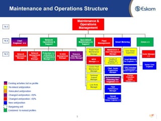
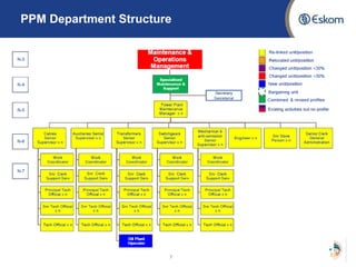
The document provides an overview of Ernst de Villiers' EIT evaluation presentation covering various departments within Eskom's power plant maintenance division. It discusses:
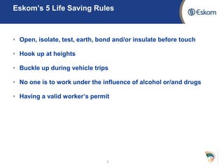
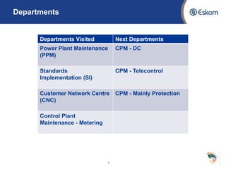
1) Eskom's life saving rules and departments visited including power plant maintenance, standards implementation, and control plant maintenance-metering.
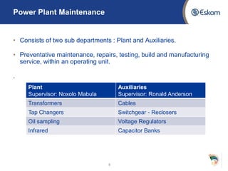
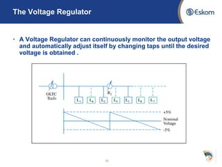
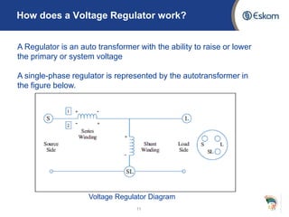
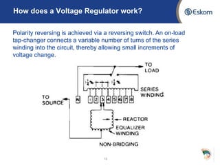
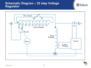
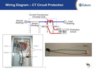
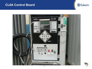
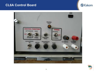
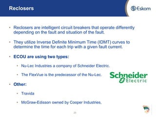
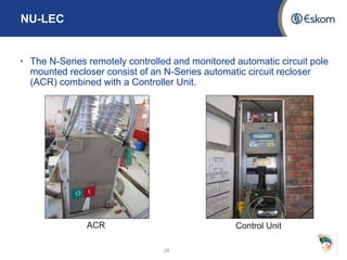
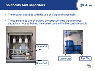
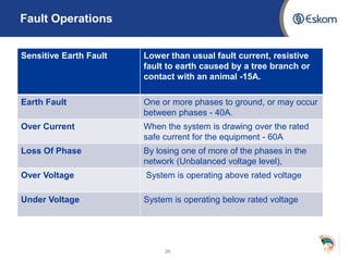
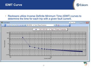
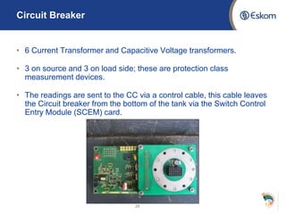
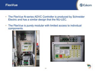
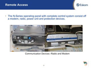
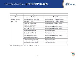
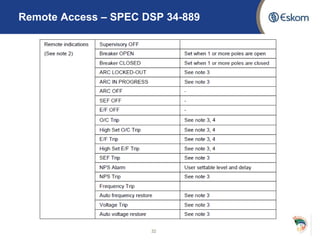
2) Key aspects of the power plant maintenance department including voltage regulators, reclosers, and the standards and processes around their maintenance and operation.
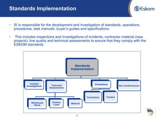
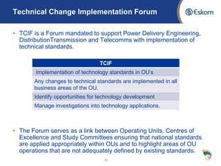
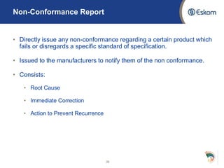
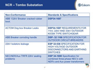
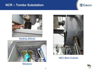
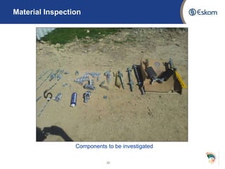
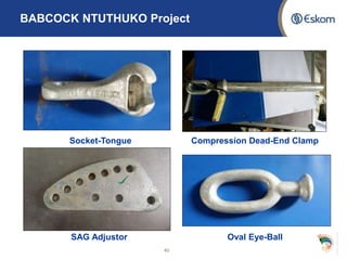
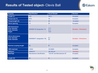
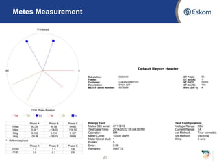
3) The role and processes of the standards implementation department relating to technical forums, non-conformance reporting, and material inspections.