Download to read offline
![ELECTRICAL PROJECTS USING MATLAB/SIMULINK
Gmail: asokatechnologies@gmail.com, Website: http://www.asokatechnologies.in
0-9347143789/9949240245
For Simulation Results of the project Contact Us
Gmail: asokatechnologies@gmail.com, Website: http://www.asokatechnologies.in
0-9347143789/9949240245
REFERENCES:
[1] M. Pavan and V. Lughi, “Grid parity in the Italian commercial and industrial electricity
market,” in Proc. Int. Conf. Clean Elect. Power (ICCEP’13), 2013, pp. 332–335.
[2] M. Delfanti, V. Olivieri, B. Erkut, and G. A. Turturro, “Reaching PV grid parity: LCOE
analysis for the Italian framework,” in Proc. 22nd Int. Conf. Exhib. Elect. Distrib. (CIRED’13),
2013, pp. 1–4.
[3] H.Wang and D. Zhang, “The stand-alone PV generation system with parallel battery
charger,” in Proc. Int. Conf. Elect. Control Eng. (ICECE’10), 2010, pp. 4450–4453.
[4] M. Kolhe, “Techno-economic optimum sizing of a stand-alone solar photovoltaic system,”
IEEE Trans. Energy Convers., vol. 24, no. 2, pp. 511–519, Jun. 2009.
[5] D. Debnath and K. Chatterjee, “A two stage solar photovoltaic based stand alone scheme
having battery as energy storage element for rural deployment,” IEEE Trans. Ind. Electron., vol.
62, no. 7, pp. 4148–4157, Jul. 2015.](https://image.slidesharecdn.com/athree-phasegridtiedspvsystemwithadaptivedclinkvoltageforcpivoltagevariations-170123102217/75/A-three-phase-grid-tied-spv-system-with-adaptive-dc-link-voltage-for-cpi-voltage-variations-7-2048.jpg)

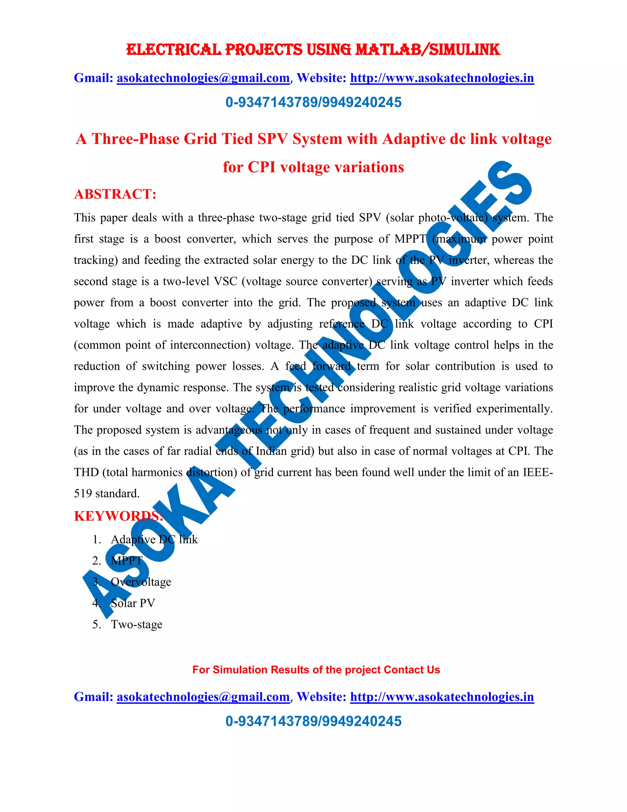
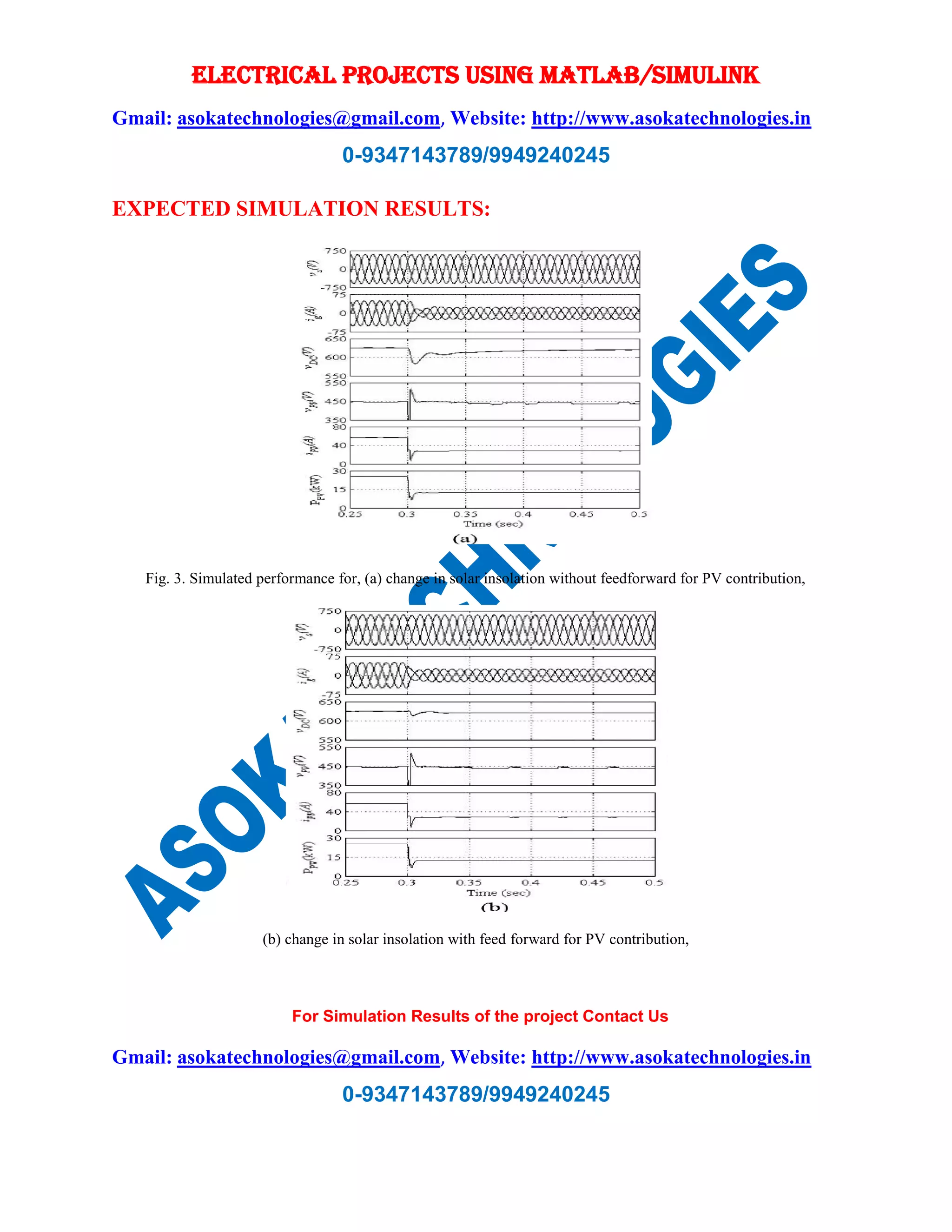
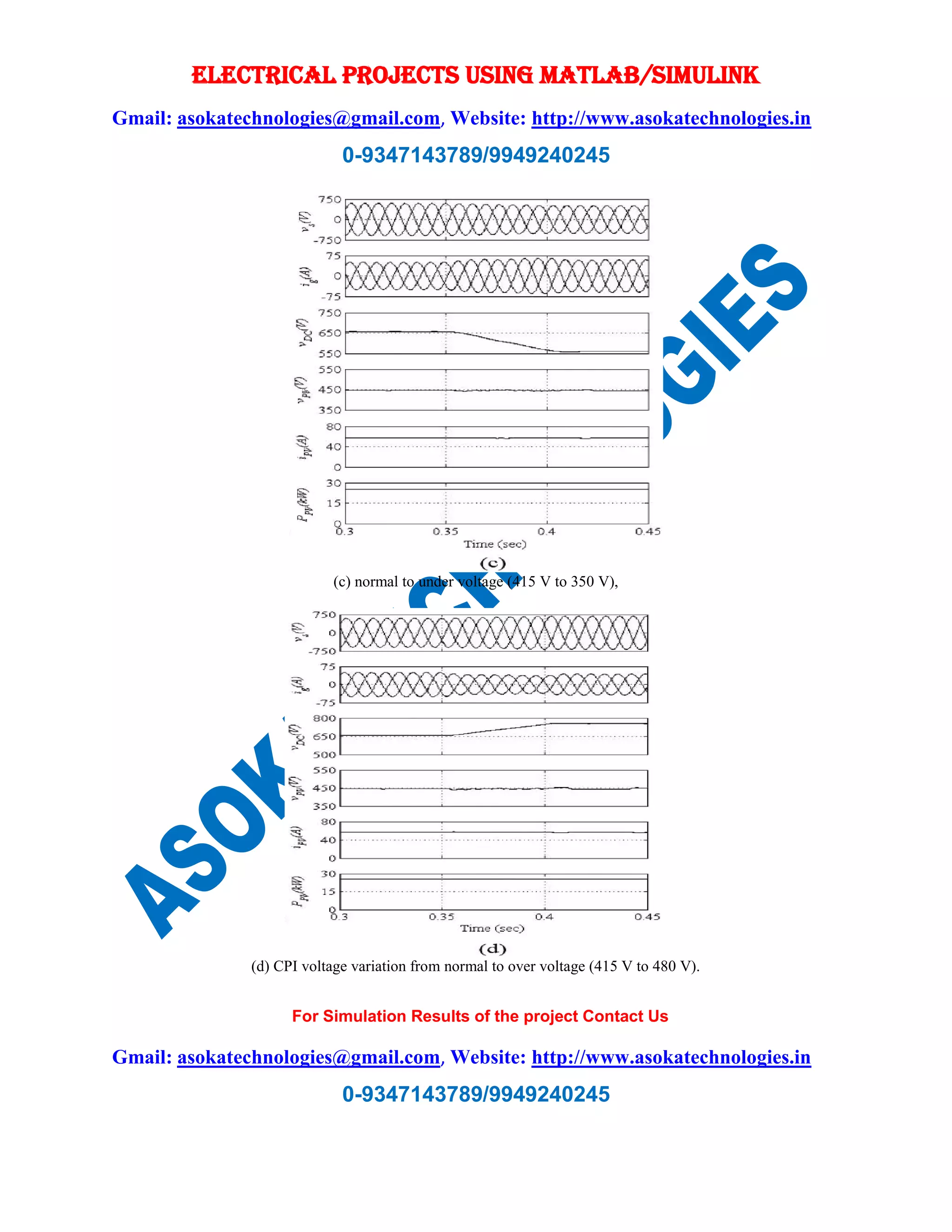
This document presents a two-stage grid-tied solar photovoltaic (PV) system that features an adaptive DC link voltage control to manage variations in the common point of interconnection (CPI) voltage. The system employs a boost converter for maximum power point tracking and a voltage source converter to feed power into the grid, showing improvements in performance and reduced switching power losses. Experimental results indicate that the proposed control algorithm effectively maintains total harmonic distortion within IEEE-519 standards and can be applied to other grid-connected devices.