Download to read offline
![ELECTRICAL PROJECTS USING MATLAB/SIMULINK
Gmail: asokatechnologies@gmail.com, Website: http://www.asokatechnologies.in
0-9347143789/9949240245
For Simulation Results of the project Contact Us
Gmail: asokatechnologies@gmail.com, Website: http://www.asokatechnologies.in
0-9347143789/9949240245
CONCLUSION:
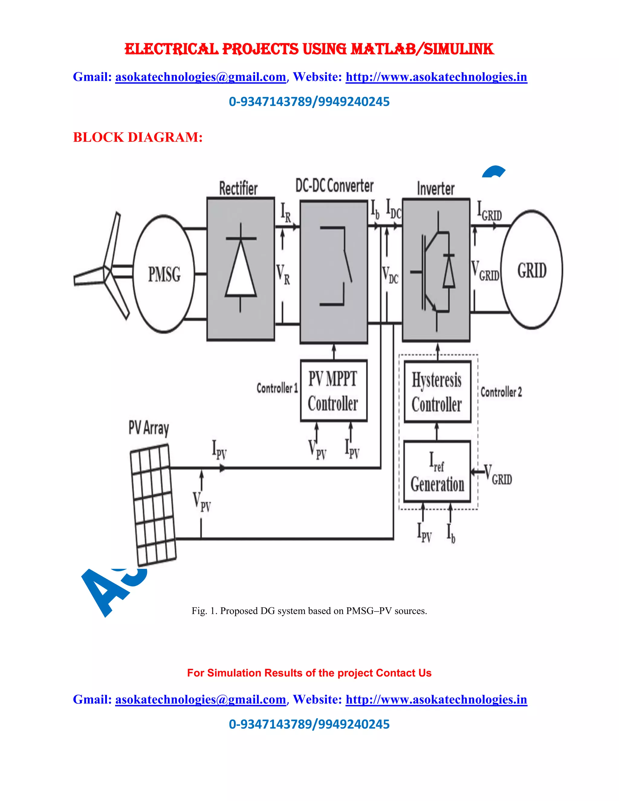
A new reliable hybrid DG system based on PV and wind driven PMSG as sources, with only a
boost converter followed by an inverter stage, has been successfully implemented. The
mathematical model developed for the proposed DG scheme has been used to study the system
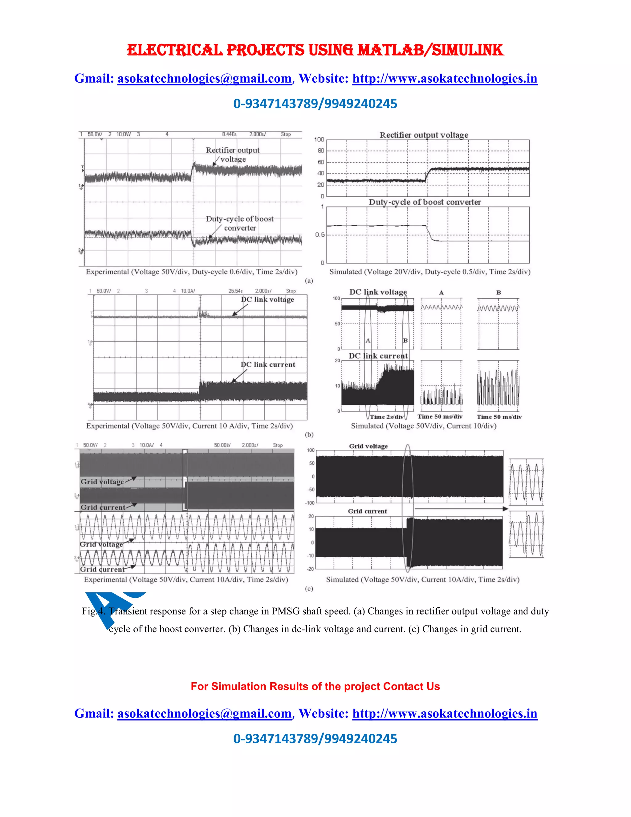
performance in MATLAB. The investigations carried out in a laboratory prototype for different
irradiations and PMSG shaft speeds amply confirm the utility of the proposed hybrid generator in
zero-net-energy buildings. In addition, it has been established through experimentation and
simulation that the two controllers, digital MPPT controller and hysteresis current controller,
which are designed specifically for the proposed system, have exactly tracked the maximum
powers from both sources. Maintenance-free operation, reliability, and low cost are the features
required for the DG employed in secondary distribution systems. It is for this reason that the
developed controllers employ very low cost microcontrollers and analog circuitry. Furthermore,
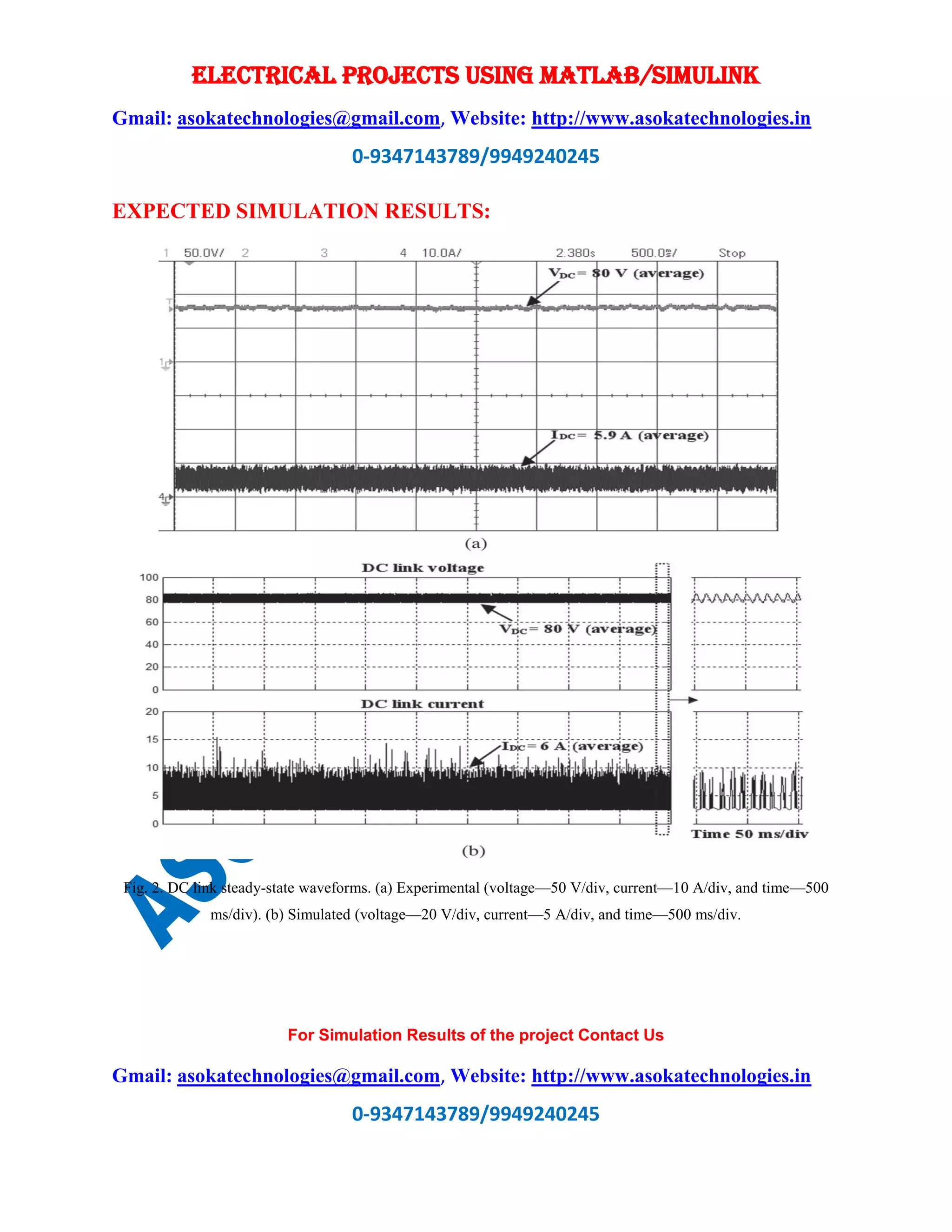
the results of the experimental investigations are found to be matching closely with the
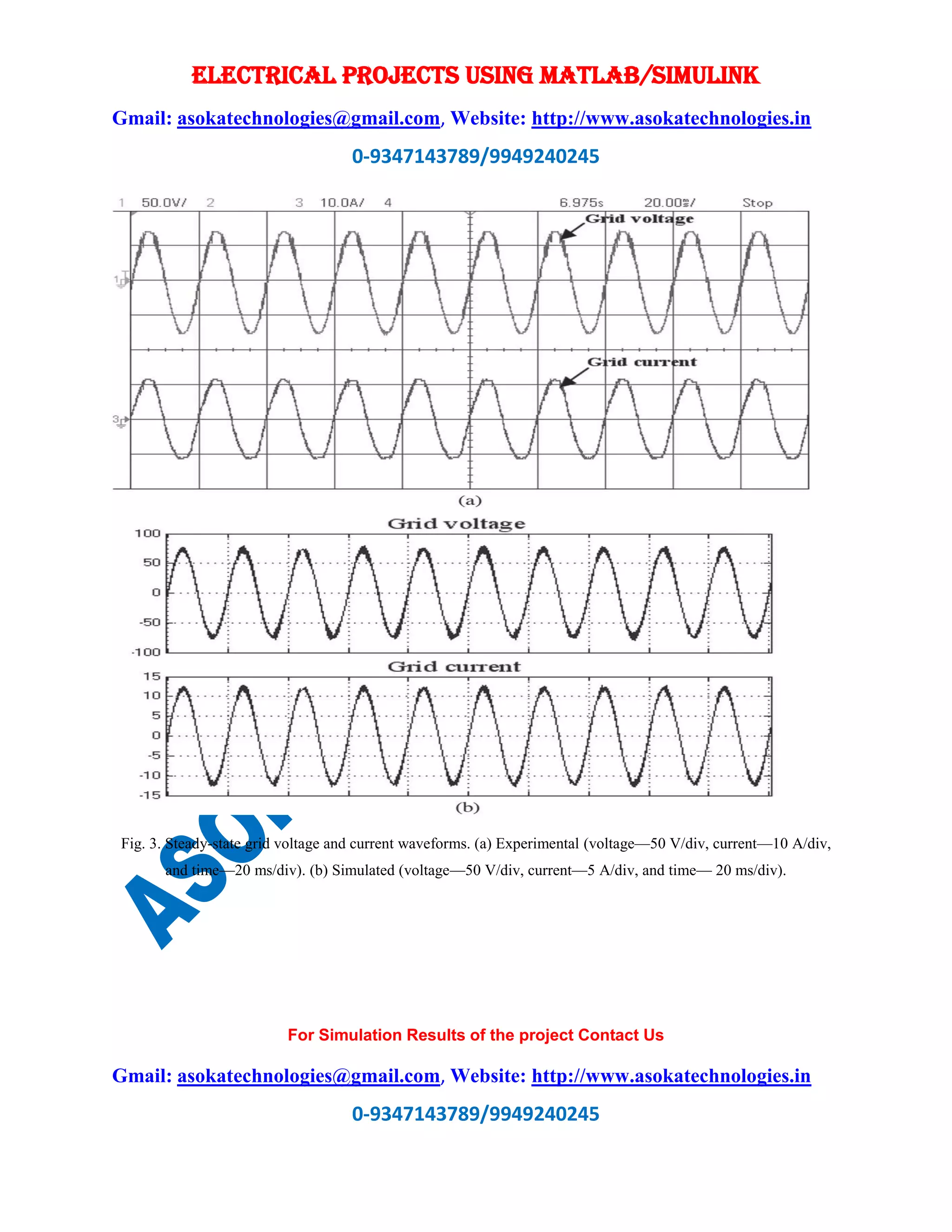
simulation results, thereby validating the developed model. The steady state waveforms captured
at the grid side show that the power generated by the DG system is fed to the grid at unity power
factor. The voltage THD and the current THD of the generator meet the required power quality
norms recommended by IEEE. The proposed scheme easily finds application for erection at
domestic consumer sites in a smart grid scenario.
REFERENCES:
[1] J. Byun, S. Park, B. Kang, I. Hong, and S. Park, “Design and implementation of an intelligent
energy saving system based on standby power reduction for a future zero-energy home
environment,” IEEE Trans. Consum. Electron., vol. 59, no. 3, pp. 507–514, Oct. 2013.
[2] J. He, Y. W. Li, and F. Blaabjerg, “Flexible microgrid power quality enhancement using
adaptive hybrid voltage and current controller,” IEEE Trans. Ind. Electron., vol. 61, no. 6, pp.
2784–2794, Jun. 2014.](https://image.slidesharecdn.com/mpptwithsingledcdcconverterandinverterforgrid-connectedhybridwind-drivenpmsgpvsystem-171111104543/75/Mppt-with-single-dc-dc-converter-and-inverter-for-grid-connected-hybrid-wind-driven-pmsg-pv-system-6-2048.jpg)
![ELECTRICAL PROJECTS USING MATLAB/SIMULINK
Gmail: asokatechnologies@gmail.com, Website: http://www.asokatechnologies.in
0-9347143789/9949240245
For Simulation Results of the project Contact Us
Gmail: asokatechnologies@gmail.com, Website: http://www.asokatechnologies.in
0-9347143789/9949240245
[3] W. Li, X. Ruan, C. Bao, D. Pan, and X. Wang, “Grid synchronization systems of three-phase
grid-connected power converters: A complexvector- filter perspective,” IEEE Trans. Ind.
Electron., vol. 61, no. 4, pp. 1855–1870, Apr. 2014.
[4] C. Liu, K. T. Chau, and X. Zhang, “An efficient wind-photovoltaic hybrid generation system
using doubly excited permanent-magnet brushless machine,” IEEE Trans. Ind. Electron, vol. 57,
no. 3, pp. 831–839, Mar. 2010.
[5] S. A. Daniel and N. A. Gounden, “A novel hybrid isolated generating system based on PV
fed inverter-assisted wind-driven induction generators,” IEEE Trans. Energy Convers., vol. 19,
no. 2, pp. 416–422, Jun. 2004.](https://image.slidesharecdn.com/mpptwithsingledcdcconverterandinverterforgrid-connectedhybridwind-drivenpmsgpvsystem-171111104543/75/Mppt-with-single-dc-dc-converter-and-inverter-for-grid-connected-hybrid-wind-driven-pmsg-pv-system-7-2048.jpg)

This document describes a new hybrid distributed generator system that uses a photovoltaic array and permanent magnet synchronous generator driven by wind to generate power. The system uses a single boost converter and inverter to connect the sources to the grid, requiring fewer power converters than previous schemes. MATLAB/Simulink is used to model and simulate the system. Low-cost controllers are proposed for the boost converter and inverter to independently track the maximum power from each source. Simulation and experimental results demonstrate the successful operation and performance of the new hybrid system.