Download to read offline
![International Research Journal of Engineering and Technology (IRJET) e-ISSN: 2395-0056
Volume: 04 Issue: 09 | Sep -2017 www.irjet.net p-ISSN: 2395-0072
© 2017, IRJET | Impact Factor value: 5.181 | ISO 9001:2008 Certified Journal | Page 306
(d) Load current
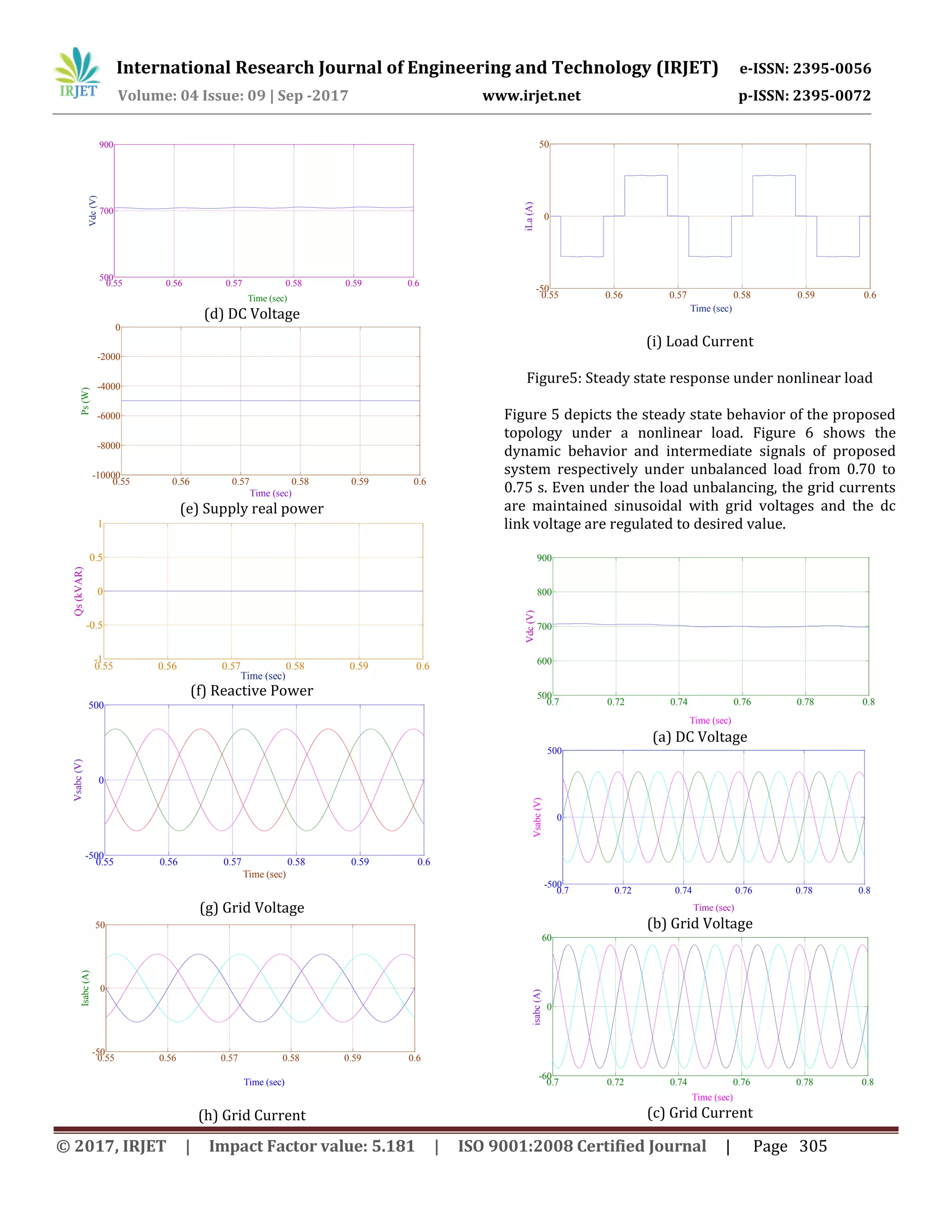
Fig.ure 6: Dynamic response under unbalanced nonlinear
load
V. CONCLUSION
In this paper, the control algorithm has been based on a
least mean fourth adaptive filtering technique is proposed.
This technique has been designed for grid connected
Photovoltaic power system. The simulation results have
depicted and maximum power is extracted from the solar
photovoltaic power system. The results of the proposed
system have proved to be efficient and consistent in
comparison with existing conventional control algorithms.
REFERENCES
[1]. P. Moutis, A. Vassilakis, A. Sampani, and N. D.
Hatziargyriou, “DC switch driven active power output
control of photovoltaic inverters for the provision of
frequency regulation,” IEEE Trans. Sustain. Energy,
vol. 6, no. 4, pp. 1485–1493, Oct. 2015.
[2]. B. Subudhi and R. Pradhan, “A comparative study on
maximum power point tracking techniques for
photovoltaic power systems,” IEEE Trans. Sustain.
Energy, vol. 4, no. 1, pp. 89–98, Jan. 2013.
[3]. K. Sundareswaran, P. Sankar, P. S. R. Nayak, S. P.
Simon, and S. Palani, “Enhanced energy output from a
PV system under partial shaded conditions through
artificial bee colony,” IEEE Trans. Sustain. Energy, vol.
6, no. 1, pp. 198–209, Jan. 2015.
[4]. C. Kai, T. Shulin, C. Yuhua, and B. Libing, “An Improved
MPPT controller for photovoltaic system under partial
shading condition,” IEEE Trans.Sustain. Energy, vol. 5,
no. 3, pp. 978–985, Jul. 2014.
[5]. S. Saxena and Y. Hote, “Load frequency control in
power systems via internal model control scheme and
model-order reduction,” IEEE Trans. Power Sys., vol.
28, no. 3, pp. 2749–2757, Aug. 2013.
[6]. P. C. Sekhar and S. Mishra, “Takagi–Sugeno fuzzy-
based incremental conductance algorithm for
maximum power point tracking of a photovoltaic
generating system,” IET Renewable Power Gener., vol.
8, no. 8, pp. 900–914, Nov. 2014.
[7]. S. K. Kollimalla and M. K. Mishra, “Variable
perturbation size adaptive P&O MPPT algorithm for
sudden changes in irradiance,” IEEE Trans. Sustain.
Energy, vol. 5, no. 3, pp. 718–728, Jul. 2014
[8]. S. A. George and F.M. Chacko, “Comparison of different
control methods for integrated system of MPPT
powered PV module and STATCOM,” in Proc. Int. Conf.
Renew. Energy Sustain. Energy, Dec. 5–6, 2013, pp.
207–212.
[9]. B. Singh, D. T. Shahani, and A. K. Verma, “IRPT based
control of a 50 kW grid interfaced solar photovoltaic
power generating system with power quality
improvement,” in Proc. IEEE 4th Int. Symp. Power
Electron. Distrib. Gener. Syst., Jul. 8–11, 2013, pp. 1–8.
[10]. B. Singh, D. T. Shahani, and A. K. Verma, “Neural
network controlled grid interfaced solar photovoltaic
power generation,” IET Power Electron., vol. 7, no. 3,
pp. 614–626, Mar. 2014.
[11]. S. Kumar, A. K. Verma, I. Hussain, and B. Singh,
“Performance of grid interfaced SPV system under
variable solar intensity,” in Proc. IEEE 6th India Int.
Conf. Power Electron., Dec. 8–10, 2014, pp. 1–6.
[12]. C. Jain and B. Singh, “A Three-phase grid tied SPV
system with adaptive DC link voltage for CPI voltage
variations,” IEEE Trans. Sustain. Energy, vol. 7, no. 1,
pp. 337–344, Jan. 2016.
[13]. E. Walach and B. Widrow, “The least mean fourth
(LMF) adaptive algorithm and its family,” IEEE Trans.
Inf. Theory, vol. 30, no. 2, pp. 275–283, Mar. 1984
[14]. G. Gui, W. Peng, and F. Adachi, “Adaptive system
identification using robust LMS/F algorithm,” Int. J.
Commun. Syst., vol. 27, pp. 2956–2963, 2014.
[15]. P. I. Hubscher, J. C.M. Bermudez, and V. H.
Nascimento, “Amean-square stability analysis of the
least mean fourth adaptive algorithm,” IEEE Trans.
Signal. Process., vol. 55, no. 8, pp. 4018–4028, Aug.
2007.
Author Details
Mr. N. Narasimhulu has completed his
professional career of education in B. Tech
(EEE) from JNTU Hyderabad in the year
2003. He obtained M. Tech degree from
JNTU, HYDERABAD, in year 2008. He is
pursuing Ph. D in the area of power system
in JNTU Anantapuramu. He has worked as
Assistant Professor from 2003-2008 and at present
working as an Associate Professor and Head of the EEE
Department in Srikrishna Devaraya Engineering College,
Gooty of Anantapuramu district (AP). He is a life member
0.7 0.72 0.74 0.76 0.78 0.8
-50
0
50
Time (sec)
iLa(A)](https://image.slidesharecdn.com/irjet-v4i952-170928094757/75/Control-of-Grid-Connected-PV-Inverter-using-LMF-Adaptive-Method-4-2048.jpg)


This document summarizes a research paper that proposes a least mean square fourth (LMF) adaptive filtering technique for controlling a single-stage, three-phase grid-connected photovoltaic (PV) inverter system. The LMF-based control algorithm is compared to existing algorithms like SRFT and IRPT, and is found to involve simpler computation, be easier to implement, more stable, faster settling time, and more reliable. Simulations in MATLAB/Simulink show the LMF approach effectively extracts maximum power from the PV system and regulates the DC link voltage even under unbalanced and nonlinear loads. The results demonstrate the efficiency and consistency of the proposed LMF-based control system compared to conventional techniques.