Download to read offline

![ELECTRICAL PROJECTS USING MATLAB/SIMULINK
Gmail: asokatechnologies@gmail.com, Website: http://www.asokatechnologies.in
0-9347143789/9949240245
For Simulation Results of the project Contact Us
Gmail: asokatechnologies@gmail.com, Website: http://www.asokatechnologies.in
0-9347143789/9949240245
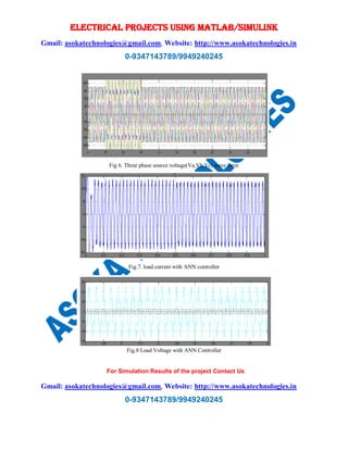
CONCLUSION:
The present topology illustrates the operation and control of Multi Converter Unified Power
Quality Conditioner (MCUPQC). The system is extended by adding a series VSC in an adjacent
feeder. A suitable mathematical have been described which establishes the fact that in both the
cases the compensation is done but the response of ANN controller is faster and the THD is
minimum for the both the voltage and current in sensitive/critical load. The device is connected
between two or more feeders coming from different substations. A non-linear/sensitive load L-1
is supplied by Feeder-1 while a sensitive/critical load L-2 is supplied through Feeder-2. The
performance of the MC-UPQC has been evaluated under various disturbance conditions such as
voltage sag/swell in either feeder, fault and load change in one of the feeders. In case of voltage
sag, the phase angle of the bus voltage in which the shunt VSC (VSC2) is connected plays an
important role as it gives the measure of the real power required by the load. The MC-UPQC can
mitigate voltage sag in Feeder-1 and in Feeder-2 for long duration.
REFERENCES:
[1] Hamid Reza Mohammadi, Ali Yazdian Varjani, and Hossein Mokhtari,“Multiconverter
Unified Power-Quality Conditioning System: MC- UPQC” IEEE RANSACTIONS ON
POWER DELIVERY, VOL. 24,NO. 3, JULY 2009.
[2] R.Rezaeipour and A.Kazemi, “Review of Novel control strategies for UPQC” Internal
Journal of Electric and power Engineering 2(4) 241-247, 2008.
[3] S. Ravi Kumar and S.Siva Nagaraju“Simulation of DSTATCOM and DVR in power
systems” Vol. 2, No. 3, June 2007 ISSN 1819-6608 ARPN Journal of Engineering and
Applied Sciences.](https://image.slidesharecdn.com/multiconverterunifiedpowerqualityconditioningsystem-181214105210/85/Multiconverter-Unified-Power-Quality-Conditioning-System-Using-Artificial-Neural-Network-Technique-6-320.jpg)
![ELECTRICAL PROJECTS USING MATLAB/SIMULINK
Gmail: asokatechnologies@gmail.com, Website: http://www.asokatechnologies.in
0-9347143789/9949240245
For Simulation Results of the project Contact Us
Gmail: asokatechnologies@gmail.com, Website: http://www.asokatechnologies.in
0-9347143789/9949240245
[4] M.V.Kasuni Perera” Control of a Dynamic Voltage Restorer to compensate single phase
voltage sags” Master of Science Thesis, Stockholm, Sweden 2007.
[5] M. Basu, S. P. Das, and G. K. Dubey, “Comparative evaluation of two models of UPQC for
suitable interface to enhance power quality,” Elect.Power Syst. Res., pp. 821–830, 2007.](https://image.slidesharecdn.com/multiconverterunifiedpowerqualityconditioningsystem-181214105210/85/Multiconverter-Unified-Power-Quality-Conditioning-System-Using-Artificial-Neural-Network-Technique-7-320.jpg)

This document discusses a new multi-converter unified power-quality conditioning system (mc-upqc) that compensates for voltage and current issues in multibus/multifeeder systems using MATLAB/Simulink simulations. The study details the effectiveness of the mc-upqc system, particularly with an artificial neural network (ANN) controller, demonstrating its performance under various disturbance conditions such as voltage sag and load changes. The results indicate that the mc-upqc can effectively mitigate voltage issues across multiple feeders, showcasing improved response and lower total harmonic distortion (THD) with the ANN controller.