Downloaded 108 times


![ENCODER REPRESENTATIONS
The encoder can be represented in several different but equivalent ways. They are
1. Generator Representation
2. Tree Diagram Representation
3. State Diagram Representation
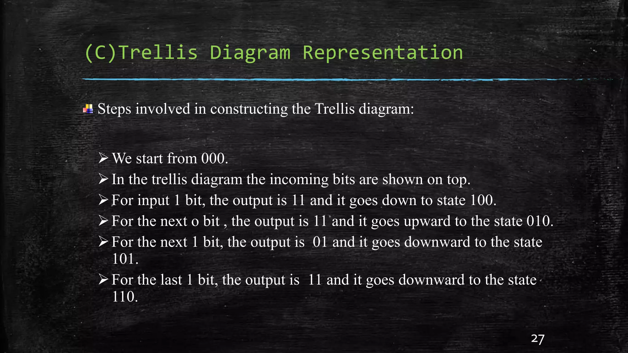
4. Trellis Diagram Representation
(A) Generator Representation
Generator representation shows the hardware connection of the shift register
taps to the modulo-2 adders. A generator vector represents the position of the taps
for an output. A “1” represents a connection and a “0” represents no connection.
For example, the two generator vectors for the encoder in Fig(a) are g1 =
[111] and g2 = [101], where the subscripts 1 and 2 denote the corresponding output
terminals.
9](https://image.slidesharecdn.com/convolutionalcodes-141026005130-conversion-gate02/75/A-Nutshell-On-Convolutional-Codes-Representations-9-2048.jpg)


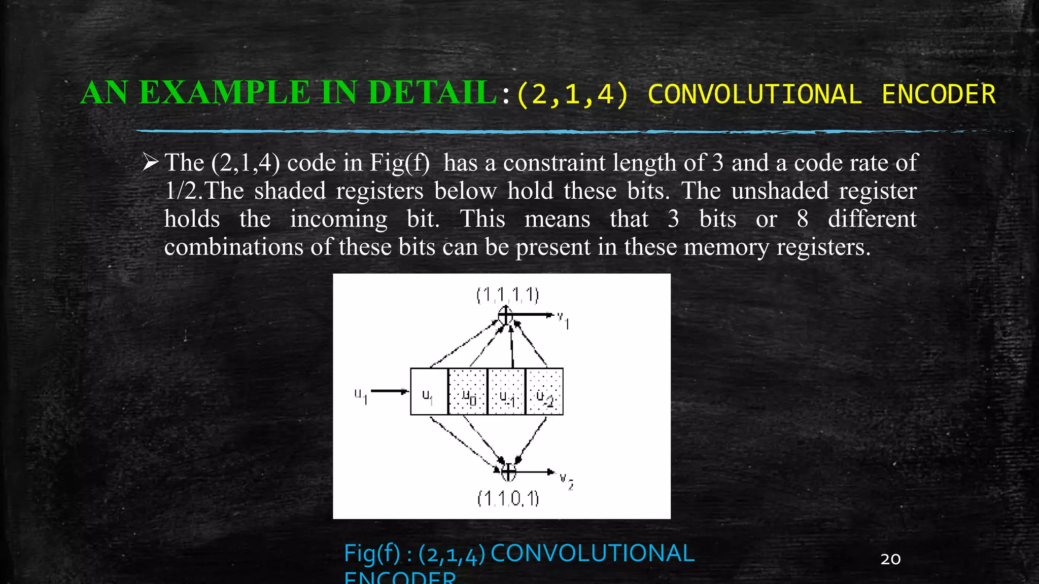


The document provides a comprehensive overview of convolutional codes, including their introduction, encoder design, representations, and advantages in error correction for digital communications. It discusses the structure of convolutional encoders, such as state diagrams and trellis diagrams, with examples illustrating the encoded sequences and parameters. Convolutional codes improve data capacity in communication channels and are effectively decoded using the Viterbi algorithm.