Communication Theory II expands on the fundamental ideas of signal transmission by introducing advanced techniques to improve the reliability and efficiency of communication systems. It emphasizes digital communication methods such as pulse code modulation, phase shift keying, frequency shift keying, and quadrature amplitude modulation. The subject also covers the effects of noise, bandwidth limitations, and distortion on signals, while providing methods like error control coding and filtering to overcome these challenges. These concepts are essential for understanding how large volumes of information can be transmitted quickly and accurately.

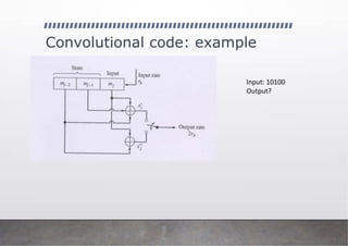
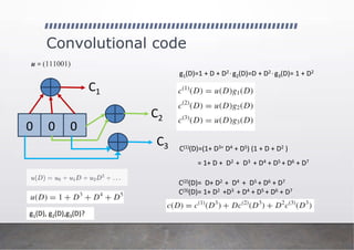
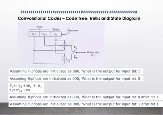
![Convolutional code
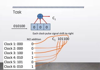
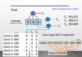
0 0 0
C1
C2
C3
g1 = [111]
g2 = [011]
g3 = [101]
c(1) = u * g1
c(2) = u * g2
c(3) = u * g3
* Convolution operator
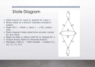
Code sequence is given by
c = c1
(1) , c1
(2), c1
(3), c2
(1) , c2
(2), c2
(3), …
convolutional operation is equivalent to multiplication
in the transform domain
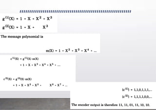
g1(D) = 1 + D + D2
g2(D) = D + D2
g3(D) = 1 + D2
c(1) = u (D) g1 (D)
c(2) = u (D) g2 (D)
c(3) = u (D) g3 (D)
impulse response
transform of the encoder output c is given by](https://image.slidesharecdn.com/communicationtheoryiilecture10-250904053353-6d8e9839/85/Communication-Theory-II_-Lecture-10-pdf-11-320.jpg)
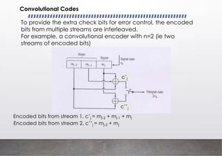
![Convolutional code
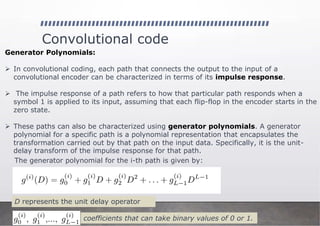
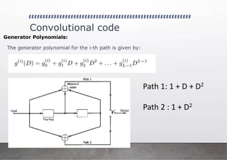
Generator Polynomials:
The generator polynomial for the i-th path is given by:
Path 1: 1 + D + D2
Path 2 : D + D2
Path 3 : 1 + D2
0 0 0
C1
C2
C3
g1 = [111]
g2 = [011]
g3 = [101]
impulse response](https://image.slidesharecdn.com/communicationtheoryiilecture10-250904053353-6d8e9839/85/Communication-Theory-II_-Lecture-10-pdf-14-320.jpg)