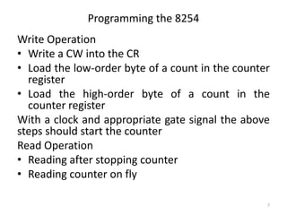
The document discusses interfacing with timers and counters using the Intel 8253/8254 Programmable Interval Timer chip. It provides information on the timer modes, programming the chip, and examples of using counters 0 and 1 to generate pulses and square waves. Specifically, it shows:
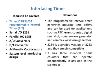
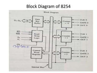
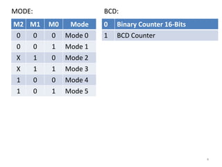
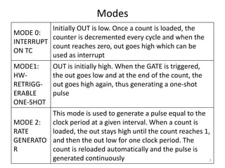
1) The 8254 timer chip has three 16-bit counters that can be programmed to operate in six different modes to generate time delays, pulses, and digital waveforms.
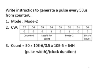
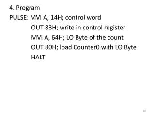
2) Examples are given to initialize counter 2 to count down from 50,000 in mode 0 and generate a 50us pulse from counter 0 in mode 2.
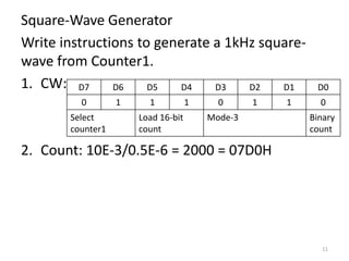
3) A third example shows how to program counter 1 to generate a 1kHz