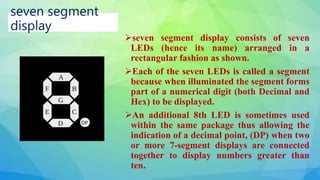
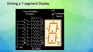
A.Vivetha MSc., Mphil., Bed.,
Assistant Professor of Physics
Bon scours College for women
seven segment
display
seven segment display consists of seven
LEDs (hence its name) arranged in a
rectangular fashion as shown.
Each of the seven LEDs is called a segment
because when illuminated the segment forms
part of a numerical digit (both Decimal and
Hex) to be displayed.
An additional 8th LED is sometimes used
within the same package thus allowing the
indication of a decimal point, (DP) when two
or more 7-segment displays are connected
together to display numbers greater than
ten.
• Each one of the seven LEDs in the display is given a
positional segment with one of its connection pins being
brought straight out of the rectangular plastic package.
These individually LED pins are labelled from a through
to g representing each individual LED. The other LED
pins are connected together and wired to form a common
pin.
• So by forward biasing the appropriate pins of the
LED segments in a particular order, some segments
will be light and others will be dark allowing the
desired character pattern of the number to be
generated on the display. This then allows us to
display each of the ten decimal digits 0 through
to 9 on the same 7-segment display.
Each LED has two connecting pins, one called the
“Anode” and the other called the “Cathode”, there
are therefore two types of LED 7-segment display
called:
Common Cathode (CC) and
Common Anode (CA).
• The difference between the two displays, as their
name suggests, is that the common cathode has all
the cathodes of the 7-segments connected directly
together and the common anode has all the anodes
of the 7-segments connected together and is
illuminated as follows.
• 1. The Common Cathode (CC) – In the common
cathode display, all the cathode connections of the
LED segments are joined together to logic “0” or
ground. The individual segments are illuminated by
application of a “HIGH”, or logic “1” signal via a
current limiting resistor to forward bias the
individual Anode terminals (a-g).
Common Cathode 7-segment Display
Common Anode 7-segment Display
• The Common Anode (CA) – In the common anode
display, all the anode connections of the LED
segments are joined together to logic “1”. The
individual segments are illuminated by applying a
ground, logic “0” or “LOW” signal via a suitable
current limiting resistor to the Cathode of the
particular segment (a-g).
• In general, common anode displays are more popular as many
logic circuits can sink more current than they can source. Also
note that a common cathode display is not a direct replacement in
a circuit for a common anode display and vice versa, as it is the
same as connecting the LEDs in reverse, and hence light emission
will not take place.
• Depending upon the decimal digit to be displayed, the particular
set of LEDs is forward biased. For instance, to display the
numerical digit 0, we will need to light up six of the LED segments
corresponding to a, b, c, d, e and f. Thus the various digits
from 0 through 9 can be displayed using a 7-segment display as
shown.
•
7-Segment Display Segments for all
Numbers.
Then for a 7-segment display, we can produce a truth table giving the
individual segments that need to be illuminated in order to produce
the required decimal digit from 0 through 9 as shown below.
7-segment Display Truth Table
Deci
mal
Digit
Individual Segments Illuminated
a b c d e f g
0 × × × × × ×
1 × ×
2 × × × × ×
3 × × × × ×
4 × × × ×
5 × × × × ×
6 × × × × × ×
7 × × ×
8 × × × × × × ×
9 × × × × ×
Driving a 7-segment Display
7 Segment Display

7 Segment Display

  • 1.
    A.Vivetha MSc., Mphil.,Bed., Assistant Professor of Physics Bon scours College for women
  • 2.
    seven segment display seven segmentdisplay consists of seven LEDs (hence its name) arranged in a rectangular fashion as shown. Each of the seven LEDs is called a segment because when illuminated the segment forms part of a numerical digit (both Decimal and Hex) to be displayed. An additional 8th LED is sometimes used within the same package thus allowing the indication of a decimal point, (DP) when two or more 7-segment displays are connected together to display numbers greater than ten.
  • 3.
    • Each oneof the seven LEDs in the display is given a positional segment with one of its connection pins being brought straight out of the rectangular plastic package. These individually LED pins are labelled from a through to g representing each individual LED. The other LED pins are connected together and wired to form a common pin.
  • 4.
    • So byforward biasing the appropriate pins of the LED segments in a particular order, some segments will be light and others will be dark allowing the desired character pattern of the number to be generated on the display. This then allows us to display each of the ten decimal digits 0 through to 9 on the same 7-segment display.
  • 5.
    Each LED hastwo connecting pins, one called the “Anode” and the other called the “Cathode”, there are therefore two types of LED 7-segment display called: Common Cathode (CC) and Common Anode (CA).
  • 6.
    • The differencebetween the two displays, as their name suggests, is that the common cathode has all the cathodes of the 7-segments connected directly together and the common anode has all the anodes of the 7-segments connected together and is illuminated as follows.
  • 7.
    • 1. TheCommon Cathode (CC) – In the common cathode display, all the cathode connections of the LED segments are joined together to logic “0” or ground. The individual segments are illuminated by application of a “HIGH”, or logic “1” signal via a current limiting resistor to forward bias the individual Anode terminals (a-g).
  • 8.
  • 9.
    Common Anode 7-segmentDisplay • The Common Anode (CA) – In the common anode display, all the anode connections of the LED segments are joined together to logic “1”. The individual segments are illuminated by applying a ground, logic “0” or “LOW” signal via a suitable current limiting resistor to the Cathode of the particular segment (a-g).
  • 10.
    • In general,common anode displays are more popular as many logic circuits can sink more current than they can source. Also note that a common cathode display is not a direct replacement in a circuit for a common anode display and vice versa, as it is the same as connecting the LEDs in reverse, and hence light emission will not take place. • Depending upon the decimal digit to be displayed, the particular set of LEDs is forward biased. For instance, to display the numerical digit 0, we will need to light up six of the LED segments corresponding to a, b, c, d, e and f. Thus the various digits from 0 through 9 can be displayed using a 7-segment display as shown. •
  • 11.
    7-Segment Display Segmentsfor all Numbers. Then for a 7-segment display, we can produce a truth table giving the individual segments that need to be illuminated in order to produce the required decimal digit from 0 through 9 as shown below.
  • 12.
    7-segment Display TruthTable Deci mal Digit Individual Segments Illuminated a b c d e f g 0 × × × × × × 1 × × 2 × × × × × 3 × × × × × 4 × × × × 5 × × × × × 6 × × × × × × 7 × × × 8 × × × × × × × 9 × × × × ×
  • 13.

Editor's Notes

  • #3 seven segment display consists of seven LEDs (hence its name) arranged in a rectangular fashion as shown. Each of the seven LEDs is called a segment because when illuminated the segment forms part of a numerical digit (both Decimal and Hex) to be displayed. An additional 8th LED is sometimes used within the same package thus allowing the indication of a decimal point, (DP) when two or more 7-segment displays are connected together to display numbers greater than ten.
  • #4 Each one of the seven LEDs in the display is given a positional segment with one of its connection pins being brought straight out of the rectangular plastic package. These individually LED pins are labelled from a through to g representing each individual LED. The other LED pins are connected together and wired to form a common pin.
  • #5 So by forward biasing the appropriate pins of the LED segments in a particular order, some segments will be light and others will be dark allowing the desired character pattern of the number to be generated on the display. This then allows us to display each of the ten decimal digits 0 through to 9 on the same 7-segment display.
  • #6 The displays common pin is generally used to identify which type of 7-segment display it is. As each LED has two connecting pins, one called the “Anode” and the other called the “Cathode”, there are therefore two types of LED 7-segment display called: Common Cathode (CC) and Common Anode (CA).
  • #7 The difference between the two displays, as their name suggests, is that the common cathode has all the cathodes of the 7-segments connected directly together and the common anode has all the anodes of the 7-segments connected together and is illuminated as follows.
  • #8 1. The Common Cathode (CC) – In the common cathode display, all the cathode connections of the LED segments are joined together to logic “0” or ground. The individual segments are illuminated by application of a “HIGH”, or logic “1” signal via a current limiting resistor to forward bias the individual Anode terminals (a-g).