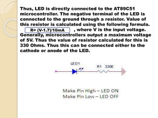
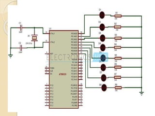
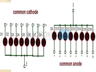
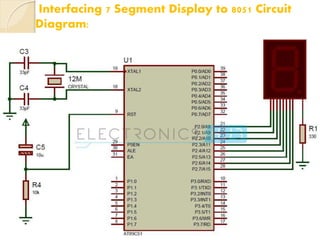
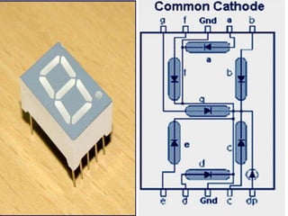
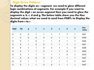
SlideShare a Scribd company logo
The circuit mainly consists of 
AT89C51 microcontroller. AT89C51 
belongs to the family of 8051 
microcontroller. It is an 8-bit 
microcontroller. This 
microcontroller has 4KB of Flash 
Programmable and Erasable Read 
Only Memory and 128 bytes of RAM. 
This can be programmed and erased 
maximum 1000times. It has two 16 
bit timers/counters. It supports 
USART communication protocol. It 
has 40 pins. There are four ports are 
designated as P0, P1, P2, P3, P4.
Light Emitting Diodes are the semi 
conductor light sources. Commonly used 
LEDs will have a cut-off voltage of 1.7V 
and current of 10mA. When an LED is 
applied with its required voltage and 
current it glows with full intensity. The 
Light Emitting Diode is similar to the 
normal PN diode but it emits energy in the 
form of light.
The Anode is connected through a resistor to 
GND & the Cathode is connected to the 
Microcontroller pin. So when the Port Pin is 
HIGH the LED is OFF & when the Port Pin is 
LOW the LED is turned ON.
In this circuit, LEDs are connected to 
the port P0. Port P0 will not have 
internal pull- ups, while the other ports 
have internal pull-ups. The controller is 
connected with external crystal 
oscillator to pin 18 and 19 pins. Crystal 
pins are connected to the ground 
through capacitors of 33pf.using an LED 
you must use a resistor to limit the 
current flow. If you just connect an LED 
directly to a pin of the micro controller 
you run the risk of damaging the micro 
controller by allowing too much current 
flow into or out of the pin.
Light Emitting Diodes are the semi 
conductor light sources. Commonly used 
LEDs will have a cut-off voltage of 1.7V and 
current of 10mA. When an LED is applied 
with its required voltage and current it 
glows with full intensity. The Light Emitting 
Diode is similar to the normal PN diode but 
it emits energy in the form of light. The 
colour of light depends on the band gap of 
the semiconductor. The following figure 
shows “how an LED glows?”
Thus, LED is directly connected to the AT89C51 
microcontroller. The negative terminal of the LED is 
connected to the ground through a resistor. Value of 
this resistor is calculated using the following formula. 
, where V is the input voltage. 
R= (V-1.7)/10mA 
Generally, microcontrollers output a maximum voltage 
of 5V. Thus the value of resistor calculated for this is 
330 Ohms. Thus this can be connected either to the 
cathode or anode of the LED.
LED Interfacing with 8051 Circuit Applications: 
LEDs are widely used in many applications like in 
seven segments. 
They are used in dot matrix displays. 
They can be used for street lights. 
They are used as indicators. 
They can be used in traffic lights. 
They are used in emergency lights 
They can used to make electronic designs.
Seven segment displays are used to indicate 
numerical information. Seven segments display 
can display digits from 0 to 9 and even we can 
display few characters like A, b, C, H, E, e, F, etc. 
These are very popular and have many more 
applications. Before going to start this concept, get 
an idea about how to interface LEDs with 8051 
Microcontroller.
Interfacing 7 Segment Display to 8051 Circuit 
Principle: 
Seven segment displays internally consist of 8 
LEDs. In these LEDs, 7 LEDs are used to indicate 
the digits 0 to 9 and single LED is used for 
indicating decimal point. Generally seven 
segments are two types, one is common 
cathode and the other is common anode. 
In common cathode, all the cathodes of LEDs are 
tied together and labeled as com. and the anode 
are left alone. In common anode, seven segment 
display all the anodes are tied together and 
cathodes are left freely. Below figure shows the 
internal connections of seven segment Display.
Interfacing 7 Segment Display to 8051 Circuit 
Diagram:
Interfacing 7 Segment Display to 8051 Circuit 
Design: 
Here, common cathode seven segment is used to 
display the digits. In this circuit, pins a to h of the 7 
segment are connected to the PORT 2 of the 
microcontroller and com pin is connected to the 
ground through the 330 ohm resistor. This resistor is 
used to drop the voltage. Since we are using 
common cathode seven segment we need to send 
LOGIC 1 to the segments to glow. 
Figure shows structure of common cathode seven 
segments. Here dot is used for indicating the decimal 
point. Here all the cathodes of LED’s are connected to 
the Gnd pin. The operating voltage of this LED’s is 2 
to 3V but from controller we will get 5V so to drop 
the remaining voltage we have to connect a to g pins 
to the controller through the resistor.
Digit Drive Pattern: 
To display the digits on 7 segment, we need to glow different 
logic combinations of segments. For example if you want to 
display the digit 3 on seven segment then you need to glow the 
segments a, b, c, d and g. The below table show you the Hex 
decimal values what we need to send from PORT2 to Display the 
digits from 0 to 9. 
Digit Dp g f e d c b a 
Hex 
value 
0 0 0 1 1 1 1 1 1 0x3f 
1 0 0 0 0 0 1 1 0 0x06 
2 0 1 0 1 1 0 1 1 0x5b 
3 0 1 0 0 1 1 1 1 0x4f 
4 0 1 1 0 0 1 1 0 0x66 
5 0 1 1 0 1 1 0 1 0x6d 
6 0 1 1 1 1 1 0 1 0x7d 
7 0 0 0 0 0 1 1 1 0x07 
8 0 1 1 1 1 1 1 1 0x7f 
9 0 1 1 0 0 1 1 1 0x67
Interfacing 7 Segment Display to 8051 
Circuit Applications: 
Seven segments are widely used in digital clocks to 
display the time. 
These are used in electronic meters for displaying 
the numerical information. 
Used in Instrument panels 
Used in digital readout displays.
Ppt on interfacing led and 7 segment with 8951

More Related Content

What's hot

Interfacing LCD with 8051 Microcontroller
Interfacing LCD with 8051 MicrocontrollerInterfacing LCD with 8051 Microcontroller
Interfacing LCD with 8051 Microcontroller
Pantech ProLabs India Pvt Ltd
 
8051 Microcontroller
8051 Microcontroller8051 Microcontroller
8051 Microcontroller
Ravikumar Tiwari
 
Interfacing technique with 8085- ADC[0808]
Interfacing technique with 8085- ADC[0808]Interfacing technique with 8085- ADC[0808]
Interfacing technique with 8085- ADC[0808]
Guhan k
 
Introduction to 8085 & it's description(includes basic lab experiments)
Introduction to 8085 & it's description(includes basic lab experiments)Introduction to 8085 & it's description(includes basic lab experiments)
Introduction to 8085 & it's description(includes basic lab experiments)
Basil John
 
Evolution of Microprocessor
Evolution of MicroprocessorEvolution of Microprocessor
Evolution of Microprocessor
Green University of Bangladesh
 
8051 programming in c
8051 programming in c8051 programming in c
8051 programming in c
Dr. Ritula Thakur
 
Seven segment interfacing with 8051.pdf
Seven segment interfacing with 8051.pdfSeven segment interfacing with 8051.pdf
Seven segment interfacing with 8051.pdf
Srikrishna Thota
 
INTRODUCTION TO MICROCONTROLLER
INTRODUCTION TO MICROCONTROLLERINTRODUCTION TO MICROCONTROLLER
INTRODUCTION TO MICROCONTROLLER
Ankita Jaiswal
 
mosfet scaling_
mosfet scaling_mosfet scaling_
mosfet scaling_
Web Design & Development
 
8051 Microcontroller ppt
8051 Microcontroller ppt8051 Microcontroller ppt
8051 Microcontroller ppt
Rahul Kumar
 
microcontroller basics
microcontroller basicsmicrocontroller basics
microcontroller basics
sagar Ramdev
 
Microcontroller 8051
Microcontroller 8051Microcontroller 8051
Microcontroller 8051
Sadiq Rahim
 
8051 Microcontroller Overview by Venkatrao Ramisetti
8051 Microcontroller Overview by Venkatrao Ramisetti 8051 Microcontroller Overview by Venkatrao Ramisetti
8051 Microcontroller Overview by Venkatrao Ramisetti
VenkatraoRamisetti
 
Sensor interfacing in 8051
Sensor interfacing in 8051Sensor interfacing in 8051
Sensor interfacing in 8051
Irfan Ahmad
 
Key board interfacing with 8051
Key board interfacing with 8051Key board interfacing with 8051
Key board interfacing with 8051
DominicHendry
 
8085 alp programs
8085 alp programs8085 alp programs
Data types in verilog
Data types in verilogData types in verilog
Data types in verilog
Nallapati Anindra
 
Ppt on interfacing led and 7 segmentwith 8951
Ppt on interfacing led  and 7 segmentwith 8951Ppt on interfacing led  and 7 segmentwith 8951
Ppt on interfacing led and 7 segmentwith 8951
pooja jaiswal
 
Alcohol Detection System in Vehicle using Arduino
Alcohol Detection System in Vehicle using ArduinoAlcohol Detection System in Vehicle using Arduino
Alcohol Detection System in Vehicle using Arduino
IRJET Journal
 

What's hot (20)

Interfacing LCD with 8051 Microcontroller
Interfacing LCD with 8051 MicrocontrollerInterfacing LCD with 8051 Microcontroller
Interfacing LCD with 8051 Microcontroller
 
8051 Microcontroller
8051 Microcontroller8051 Microcontroller
8051 Microcontroller
 
Interfacing technique with 8085- ADC[0808]
Interfacing technique with 8085- ADC[0808]Interfacing technique with 8085- ADC[0808]
Interfacing technique with 8085- ADC[0808]
 
Introduction to 8085 & it's description(includes basic lab experiments)
Introduction to 8085 & it's description(includes basic lab experiments)Introduction to 8085 & it's description(includes basic lab experiments)
Introduction to 8085 & it's description(includes basic lab experiments)
 
Evolution of Microprocessor
Evolution of MicroprocessorEvolution of Microprocessor
Evolution of Microprocessor
 
8051 programming in c
8051 programming in c8051 programming in c
8051 programming in c
 
Seven segment interfacing with 8051.pdf
Seven segment interfacing with 8051.pdfSeven segment interfacing with 8051.pdf
Seven segment interfacing with 8051.pdf
 
INTRODUCTION TO MICROCONTROLLER
INTRODUCTION TO MICROCONTROLLERINTRODUCTION TO MICROCONTROLLER
INTRODUCTION TO MICROCONTROLLER
 
mosfet scaling_
mosfet scaling_mosfet scaling_
mosfet scaling_
 
8051 Microcontroller ppt
8051 Microcontroller ppt8051 Microcontroller ppt
8051 Microcontroller ppt
 
MICROCONTROLLER 8051
MICROCONTROLLER 8051MICROCONTROLLER 8051
MICROCONTROLLER 8051
 
microcontroller basics
microcontroller basicsmicrocontroller basics
microcontroller basics
 
Microcontroller 8051
Microcontroller 8051Microcontroller 8051
Microcontroller 8051
 
8051 Microcontroller Overview by Venkatrao Ramisetti
8051 Microcontroller Overview by Venkatrao Ramisetti 8051 Microcontroller Overview by Venkatrao Ramisetti
8051 Microcontroller Overview by Venkatrao Ramisetti
 
Sensor interfacing in 8051
Sensor interfacing in 8051Sensor interfacing in 8051
Sensor interfacing in 8051
 
Key board interfacing with 8051
Key board interfacing with 8051Key board interfacing with 8051
Key board interfacing with 8051
 
8085 alp programs
8085 alp programs8085 alp programs
8085 alp programs
 
Data types in verilog
Data types in verilogData types in verilog
Data types in verilog
 
Ppt on interfacing led and 7 segmentwith 8951
Ppt on interfacing led  and 7 segmentwith 8951Ppt on interfacing led  and 7 segmentwith 8951
Ppt on interfacing led and 7 segmentwith 8951
 
Alcohol Detection System in Vehicle using Arduino
Alcohol Detection System in Vehicle using ArduinoAlcohol Detection System in Vehicle using Arduino
Alcohol Detection System in Vehicle using Arduino
 

Similar to Ppt on interfacing led and 7 segment with 8951

Basi electroni components lecture
Basi electroni components lectureBasi electroni components lecture
Basi electroni components lecture
CherehaniMakigo
 
Nand gate breadboardtask
Nand gate breadboardtaskNand gate breadboardtask
Nand gate breadboardtask
shankarganesh73
 
8051interfacing 190425062221
8051interfacing 1904250622218051interfacing 190425062221
8051interfacing 190425062221
Indranil Hatai
 
1396740 634706422070340000
1396740 6347064220703400001396740 634706422070340000
1396740 634706422070340000bnsprasad
 
PIC Microcontroller
PIC MicrocontrollerPIC Microcontroller
PIC Microcontroller
Divya Bansal
 
Basic-Electronic-Components .pdf
Basic-Electronic-Components         .pdfBasic-Electronic-Components         .pdf
Basic-Electronic-Components .pdf
Desalechali1
 
Microcontroller ppt
Microcontroller pptMicrocontroller ppt
Microcontroller ppt
prajjwalsharma37
 
Remotely Secured Device Automation using Infrared
Remotely Secured Device Automation using InfraredRemotely Secured Device Automation using Infrared
Remotely Secured Device Automation using Infrared
ijsrd.com
 
Real Analog - Circuits 1Chapter 1 Lab WorksheetsReal Analog – .docx
Real Analog - Circuits 1Chapter 1 Lab WorksheetsReal Analog –  .docxReal Analog - Circuits 1Chapter 1 Lab WorksheetsReal Analog –  .docx
Real Analog - Circuits 1Chapter 1 Lab WorksheetsReal Analog – .docx
catheryncouper
 
Battery level Indicator Circuit
Battery level Indicator CircuitBattery level Indicator Circuit
Battery level Indicator Circuit
Uzair Ahmad
 
Seven Segment Display
Seven Segment DisplaySeven Segment Display
Seven Segment Display
Kshitij Wagle
 
International Journal of Engineering Research and Development
International Journal of Engineering Research and DevelopmentInternational Journal of Engineering Research and Development
International Journal of Engineering Research and Development
IJERD Editor
 
Report of Battery Level Indicator Circuit
Report of Battery Level Indicator CircuitReport of Battery Level Indicator Circuit
Report of Battery Level Indicator Circuit
Uzair Ahmad
 
Embedded System[586]
Embedded System[586]Embedded System[586]
Embedded System[586]
ajeet singh choudhary
 
Ade manual final
Ade manual finalAde manual final
Ade manual final
Devendra Kushwaha
 
Lec 8,9,10 (interfacing)
Lec 8,9,10 (interfacing)Lec 8,9,10 (interfacing)
Lec 8,9,10 (interfacing)
Mohamed Atef
 
Temperature Based Fan Controller
Temperature Based Fan Controller Temperature Based Fan Controller
Temperature Based Fan Controller
richa1910n
 
Switches and LEDs interface to the 8051 microcontroller
Switches and LEDs interface to the 8051 microcontrollerSwitches and LEDs interface to the 8051 microcontroller
Switches and LEDs interface to the 8051 microcontroller
University of Technology - Iraq
 

Similar to Ppt on interfacing led and 7 segment with 8951 (20)

Basi electroni components lecture
Basi electroni components lectureBasi electroni components lecture
Basi electroni components lecture
 
PROJECT ENGINEERIING (1)
PROJECT ENGINEERIING (1)PROJECT ENGINEERIING (1)
PROJECT ENGINEERIING (1)
 
Nand gate breadboardtask
Nand gate breadboardtaskNand gate breadboardtask
Nand gate breadboardtask
 
8051interfacing 190425062221
8051interfacing 1904250622218051interfacing 190425062221
8051interfacing 190425062221
 
1396740 634706422070340000
1396740 6347064220703400001396740 634706422070340000
1396740 634706422070340000
 
PIC Microcontroller
PIC MicrocontrollerPIC Microcontroller
PIC Microcontroller
 
Basic-Electronic-Components .pdf
Basic-Electronic-Components         .pdfBasic-Electronic-Components         .pdf
Basic-Electronic-Components .pdf
 
Microcontroller ppt
Microcontroller pptMicrocontroller ppt
Microcontroller ppt
 
Remotely Secured Device Automation using Infrared
Remotely Secured Device Automation using InfraredRemotely Secured Device Automation using Infrared
Remotely Secured Device Automation using Infrared
 
Real Analog - Circuits 1Chapter 1 Lab WorksheetsReal Analog – .docx
Real Analog - Circuits 1Chapter 1 Lab WorksheetsReal Analog –  .docxReal Analog - Circuits 1Chapter 1 Lab WorksheetsReal Analog –  .docx
Real Analog - Circuits 1Chapter 1 Lab WorksheetsReal Analog – .docx
 
Battery level Indicator Circuit
Battery level Indicator CircuitBattery level Indicator Circuit
Battery level Indicator Circuit
 
Seven Segment Display
Seven Segment DisplaySeven Segment Display
Seven Segment Display
 
International Journal of Engineering Research and Development
International Journal of Engineering Research and DevelopmentInternational Journal of Engineering Research and Development
International Journal of Engineering Research and Development
 
Report of Battery Level Indicator Circuit
Report of Battery Level Indicator CircuitReport of Battery Level Indicator Circuit
Report of Battery Level Indicator Circuit
 
Embedded System[586]
Embedded System[586]Embedded System[586]
Embedded System[586]
 
Est 6
Est 6Est 6
Est 6
 
Ade manual final
Ade manual finalAde manual final
Ade manual final
 
Lec 8,9,10 (interfacing)
Lec 8,9,10 (interfacing)Lec 8,9,10 (interfacing)
Lec 8,9,10 (interfacing)
 
Temperature Based Fan Controller
Temperature Based Fan Controller Temperature Based Fan Controller
Temperature Based Fan Controller
 
Switches and LEDs interface to the 8051 microcontroller
Switches and LEDs interface to the 8051 microcontrollerSwitches and LEDs interface to the 8051 microcontroller
Switches and LEDs interface to the 8051 microcontroller
 

Ppt on interfacing led and 7 segment with 8951

  • 1.
  • 2. The circuit mainly consists of AT89C51 microcontroller. AT89C51 belongs to the family of 8051 microcontroller. It is an 8-bit microcontroller. This microcontroller has 4KB of Flash Programmable and Erasable Read Only Memory and 128 bytes of RAM. This can be programmed and erased maximum 1000times. It has two 16 bit timers/counters. It supports USART communication protocol. It has 40 pins. There are four ports are designated as P0, P1, P2, P3, P4.
  • 3. Light Emitting Diodes are the semi conductor light sources. Commonly used LEDs will have a cut-off voltage of 1.7V and current of 10mA. When an LED is applied with its required voltage and current it glows with full intensity. The Light Emitting Diode is similar to the normal PN diode but it emits energy in the form of light.
  • 4. The Anode is connected through a resistor to GND & the Cathode is connected to the Microcontroller pin. So when the Port Pin is HIGH the LED is OFF & when the Port Pin is LOW the LED is turned ON.
  • 5. In this circuit, LEDs are connected to the port P0. Port P0 will not have internal pull- ups, while the other ports have internal pull-ups. The controller is connected with external crystal oscillator to pin 18 and 19 pins. Crystal pins are connected to the ground through capacitors of 33pf.using an LED you must use a resistor to limit the current flow. If you just connect an LED directly to a pin of the micro controller you run the risk of damaging the micro controller by allowing too much current flow into or out of the pin.
  • 6. Light Emitting Diodes are the semi conductor light sources. Commonly used LEDs will have a cut-off voltage of 1.7V and current of 10mA. When an LED is applied with its required voltage and current it glows with full intensity. The Light Emitting Diode is similar to the normal PN diode but it emits energy in the form of light. The colour of light depends on the band gap of the semiconductor. The following figure shows “how an LED glows?”
  • 7. Thus, LED is directly connected to the AT89C51 microcontroller. The negative terminal of the LED is connected to the ground through a resistor. Value of this resistor is calculated using the following formula. , where V is the input voltage. R= (V-1.7)/10mA Generally, microcontrollers output a maximum voltage of 5V. Thus the value of resistor calculated for this is 330 Ohms. Thus this can be connected either to the cathode or anode of the LED.
  • 8. LED Interfacing with 8051 Circuit Applications: LEDs are widely used in many applications like in seven segments. They are used in dot matrix displays. They can be used for street lights. They are used as indicators. They can be used in traffic lights. They are used in emergency lights They can used to make electronic designs.
  • 9.
  • 10.
  • 11.
  • 12. Seven segment displays are used to indicate numerical information. Seven segments display can display digits from 0 to 9 and even we can display few characters like A, b, C, H, E, e, F, etc. These are very popular and have many more applications. Before going to start this concept, get an idea about how to interface LEDs with 8051 Microcontroller.
  • 13. Interfacing 7 Segment Display to 8051 Circuit Principle: Seven segment displays internally consist of 8 LEDs. In these LEDs, 7 LEDs are used to indicate the digits 0 to 9 and single LED is used for indicating decimal point. Generally seven segments are two types, one is common cathode and the other is common anode. In common cathode, all the cathodes of LEDs are tied together and labeled as com. and the anode are left alone. In common anode, seven segment display all the anodes are tied together and cathodes are left freely. Below figure shows the internal connections of seven segment Display.
  • 14.
  • 15. Interfacing 7 Segment Display to 8051 Circuit Diagram:
  • 16. Interfacing 7 Segment Display to 8051 Circuit Design: Here, common cathode seven segment is used to display the digits. In this circuit, pins a to h of the 7 segment are connected to the PORT 2 of the microcontroller and com pin is connected to the ground through the 330 ohm resistor. This resistor is used to drop the voltage. Since we are using common cathode seven segment we need to send LOGIC 1 to the segments to glow. Figure shows structure of common cathode seven segments. Here dot is used for indicating the decimal point. Here all the cathodes of LED’s are connected to the Gnd pin. The operating voltage of this LED’s is 2 to 3V but from controller we will get 5V so to drop the remaining voltage we have to connect a to g pins to the controller through the resistor.
  • 17.
  • 18. Digit Drive Pattern: To display the digits on 7 segment, we need to glow different logic combinations of segments. For example if you want to display the digit 3 on seven segment then you need to glow the segments a, b, c, d and g. The below table show you the Hex decimal values what we need to send from PORT2 to Display the digits from 0 to 9. Digit Dp g f e d c b a Hex value 0 0 0 1 1 1 1 1 1 0x3f 1 0 0 0 0 0 1 1 0 0x06 2 0 1 0 1 1 0 1 1 0x5b 3 0 1 0 0 1 1 1 1 0x4f 4 0 1 1 0 0 1 1 0 0x66 5 0 1 1 0 1 1 0 1 0x6d 6 0 1 1 1 1 1 0 1 0x7d 7 0 0 0 0 0 1 1 1 0x07 8 0 1 1 1 1 1 1 1 0x7f 9 0 1 1 0 0 1 1 1 0x67
  • 19. Interfacing 7 Segment Display to 8051 Circuit Applications: Seven segments are widely used in digital clocks to display the time. These are used in electronic meters for displaying the numerical information. Used in Instrument panels Used in digital readout displays.