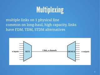
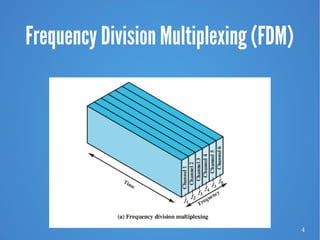
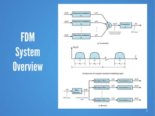
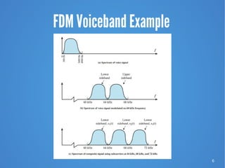
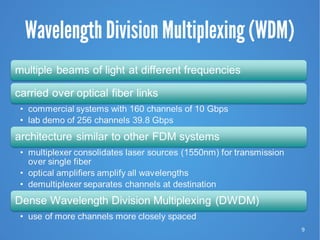
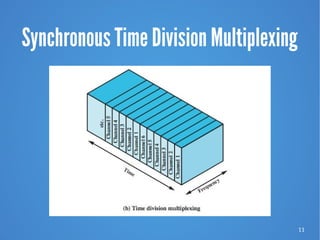
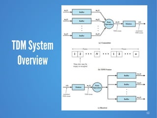
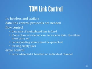
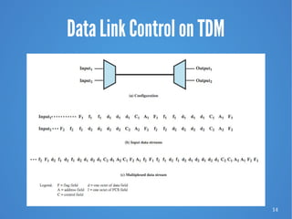
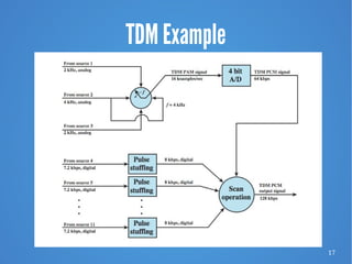
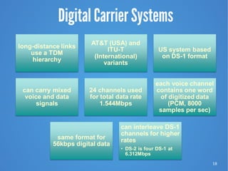
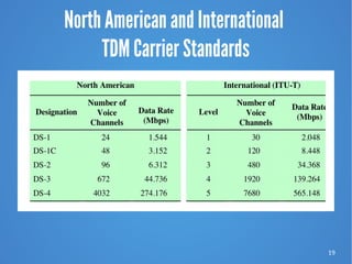
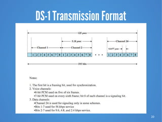
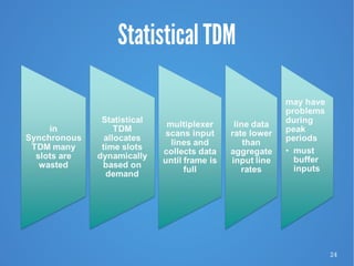
Multiplexing
CEN 220/CIS 192 Advanced Data Communications and Networking
Data and Computer Communications, W. Stallings 9/E, Chapter 8
2
Multiplexing
“It was impossible to get a conversation going,
everybody was talking too much.”
—Yogi Berra
3
Multiplexing
multiple links on 1 physical line
common on long-haul, high capacity, links
have FDM, TDM, STDM alternatives
4
Frequency Division Multiplexing (FDM)
5
FDM
System
Overview
6
FDM Voiceband Example
7
Analog Carrier Systems
long-distance links use an FDM hierarchy
AT&T (USA) and ITU-T (International) variants
Group

12 voice channels (4 kHz each) = 48 kHz

Range 60 kHz to 108 kHz
Supergroup

FDM of 5 group signals supports 60 channels

carriers between 420 kHz and 612 kHz
Mastergroup

FDM of 10 supergroups supports 600 channels
original signal can be modulated many times
8
North American and International FDM
Carrier Standards
9
Wavelength Division Multiplexing (WDM)
10
ITU WDM Channel Spacing (G.692)
11
Synchronous Time Division Multiplexing
12
TDM System
Overview
13
TDM Link Control
no headers and trailers
data link control protocols not needed
flow control
 data rate of multiplexed line is fixed
 if one channel receiver can not receive data, the others
must carry on
 corresponding source must be quenched
 leaving empty slots
error control
 errors detected & handled on individual channel
14
Data Link Control on TDM
15
Framing
no flag or SYNC chars bracketing TDM frames
must still provide synchronizing mechanism between
source and destination clocks
added digit framing is most common

one control bit added to each TDM frame

identifiable bit pattern used as control channel

alternating pattern 101010…unlikely to be sustained on a
data channel

receivers compare incoming bits of frame position to the
expected pattern
16
Pulse Stuffing
– problem of synchronizing various data sources
– variation among clocks could cause loss of
synchronization
– issue of data rates from different sources not related by a
simple rational number
17
TDM Example
18
Digital Carrier Systems
19
North American and International
TDM Carrier Standards
20
DS-1 Transmission Format
21
SONET/SDH
Synchronous Optical Network (ANSI)
Synchronous Digital Hierarchy (ITU-T)
high speed capability of optical fiber
defines hierarchy of signal rates
– Synchronous Transport Signal level 1 (STS-1) or
– Optical Carrier level 1 (OC-1) is 51.84 Mbps
– carries one DS-3 or multiple (DS1 DS1C DS2)
plus ITU-T rates (e.g., 2.048 Mbps)
– multiple STS-1 combine into STS-N signal
– ITU-T lowest rate is 155.52 Mbps (STM-1)
22
SONET/SDH Signal Hierarchy
23
SONET Frame Format
24
Statistical TDM
25
Statistical TDM Frame Format
26
Single-Server Queues with Constant Service Times
and Poisson (Random) Arrivals
27
Cable Modems
– dedicate two cable TV channels to data transfer
– each channel shared by number of subscribers using
statistical TDM
28
Cable Spectrum Division
To support both cable television programming and data
channels, the cable spectrum is divided in to three ranges:

user-to-network data (upstream): 5 - 40 MHz

television delivery (downstream): 50 - 550 MHz

network to user data (downstream): 550 - 750 MHz
29
Cable Modem Scheme
30
Asymmetrical Digital Subscriber Line (ADSL)
link between subscriber and network
uses currently installed twisted pair cable
is Asymmetric - bigger downstream than up
uses Frequency Division Multiplexing

reserve lowest 25 kHz for voice (POTS)

uses echo cancellation or FDM to give two bands
has a range of up to 5.5 km
31
ADSL Channel Configuration
32
Discrete Multitone (DMT)
multiple carrier signals at different frequencies
divide into 4 kHz subchannels
test and use subchannels with better SNR
256 downstream subchannels at 4 kHz (60 kbps)

in theory 15.36 Mbps, in practice 1.5-9 Mbps
33
DMT Transmitter
34
Broadband – Customer Side
DSL link is between provider and customer
a splitter allows simultaneous telephone and data
service
data services use a DSL modem

sometimes referred to as G.DMT modem
DSL data signal can be divided into a video stream and
a data stream

the data stream connects the modem to a router which
enables a customer to support a wireless local area
network
35
Broadband – Provider Side
a splitter separates telephone from Internet
voice traffic is connected to public switched
telephone network (PSTN)
data traffic connects to a DSL multiplexer (DSLAM)
which multiplexes multiple customer DSL
connections to a single high-speed ATM line.
ATM line connects ATM switches to a router which
provides entry to the Internet
36
xDSL
high data rate DSL (HDSL)

2B1Q coding on dual twisted pairs

up to 2Mbps over 3.7km
single line DSL

2B1Q coding on single twisted pair (residential) with
echo cancelling

up to 2Mbps over 3.7km
very high data rate DSL

DMT/QAM for very high data rates

separate bands for separate services
37
Comparison of xDSL Alternatives
38
Summary
Multiplexing multiple channels on single link
FDM

analog carrier systems

wavelength division multiplexing
TDM

TDM link control

pulse stuffing
statistical TDM
broadband
ADSL and xDSL

Chapter 8 - Multiplexing 9e

  • 1.
    Multiplexing CEN 220/CIS 192Advanced Data Communications and Networking Data and Computer Communications, W. Stallings 9/E, Chapter 8
  • 2.
    2 Multiplexing “It was impossibleto get a conversation going, everybody was talking too much.” —Yogi Berra
  • 3.
    3 Multiplexing multiple links on1 physical line common on long-haul, high capacity, links have FDM, TDM, STDM alternatives
  • 4.
  • 5.
  • 6.
  • 7.
    7 Analog Carrier Systems long-distancelinks use an FDM hierarchy AT&T (USA) and ITU-T (International) variants Group  12 voice channels (4 kHz each) = 48 kHz  Range 60 kHz to 108 kHz Supergroup  FDM of 5 group signals supports 60 channels  carriers between 420 kHz and 612 kHz Mastergroup  FDM of 10 supergroups supports 600 channels original signal can be modulated many times
  • 8.
    8 North American andInternational FDM Carrier Standards
  • 9.
  • 10.
    10 ITU WDM ChannelSpacing (G.692)
  • 11.
  • 12.
  • 13.
    13 TDM Link Control noheaders and trailers data link control protocols not needed flow control  data rate of multiplexed line is fixed  if one channel receiver can not receive data, the others must carry on  corresponding source must be quenched  leaving empty slots error control  errors detected & handled on individual channel
  • 14.
  • 15.
    15 Framing no flag orSYNC chars bracketing TDM frames must still provide synchronizing mechanism between source and destination clocks added digit framing is most common  one control bit added to each TDM frame  identifiable bit pattern used as control channel  alternating pattern 101010…unlikely to be sustained on a data channel  receivers compare incoming bits of frame position to the expected pattern
  • 16.
    16 Pulse Stuffing – problemof synchronizing various data sources – variation among clocks could cause loss of synchronization – issue of data rates from different sources not related by a simple rational number
  • 17.
  • 18.
  • 19.
    19 North American andInternational TDM Carrier Standards
  • 20.
  • 21.
    21 SONET/SDH Synchronous Optical Network(ANSI) Synchronous Digital Hierarchy (ITU-T) high speed capability of optical fiber defines hierarchy of signal rates – Synchronous Transport Signal level 1 (STS-1) or – Optical Carrier level 1 (OC-1) is 51.84 Mbps – carries one DS-3 or multiple (DS1 DS1C DS2) plus ITU-T rates (e.g., 2.048 Mbps) – multiple STS-1 combine into STS-N signal – ITU-T lowest rate is 155.52 Mbps (STM-1)
  • 22.
  • 23.
  • 24.
  • 25.
  • 26.
    26 Single-Server Queues withConstant Service Times and Poisson (Random) Arrivals
  • 27.
    27 Cable Modems – dedicatetwo cable TV channels to data transfer – each channel shared by number of subscribers using statistical TDM
  • 28.
    28 Cable Spectrum Division Tosupport both cable television programming and data channels, the cable spectrum is divided in to three ranges:  user-to-network data (upstream): 5 - 40 MHz  television delivery (downstream): 50 - 550 MHz  network to user data (downstream): 550 - 750 MHz
  • 29.
  • 30.
    30 Asymmetrical Digital SubscriberLine (ADSL) link between subscriber and network uses currently installed twisted pair cable is Asymmetric - bigger downstream than up uses Frequency Division Multiplexing  reserve lowest 25 kHz for voice (POTS)  uses echo cancellation or FDM to give two bands has a range of up to 5.5 km
  • 31.
  • 32.
    32 Discrete Multitone (DMT) multiplecarrier signals at different frequencies divide into 4 kHz subchannels test and use subchannels with better SNR 256 downstream subchannels at 4 kHz (60 kbps)  in theory 15.36 Mbps, in practice 1.5-9 Mbps
  • 33.
  • 34.
    34 Broadband – CustomerSide DSL link is between provider and customer a splitter allows simultaneous telephone and data service data services use a DSL modem  sometimes referred to as G.DMT modem DSL data signal can be divided into a video stream and a data stream  the data stream connects the modem to a router which enables a customer to support a wireless local area network
  • 35.
    35 Broadband – ProviderSide a splitter separates telephone from Internet voice traffic is connected to public switched telephone network (PSTN) data traffic connects to a DSL multiplexer (DSLAM) which multiplexes multiple customer DSL connections to a single high-speed ATM line. ATM line connects ATM switches to a router which provides entry to the Internet
  • 36.
    36 xDSL high data rateDSL (HDSL)  2B1Q coding on dual twisted pairs  up to 2Mbps over 3.7km single line DSL  2B1Q coding on single twisted pair (residential) with echo cancelling  up to 2Mbps over 3.7km very high data rate DSL  DMT/QAM for very high data rates  separate bands for separate services
  • 37.
  • 38.
    38 Summary Multiplexing multiple channelson single link FDM  analog carrier systems  wavelength division multiplexing TDM  TDM link control  pulse stuffing statistical TDM broadband ADSL and xDSL