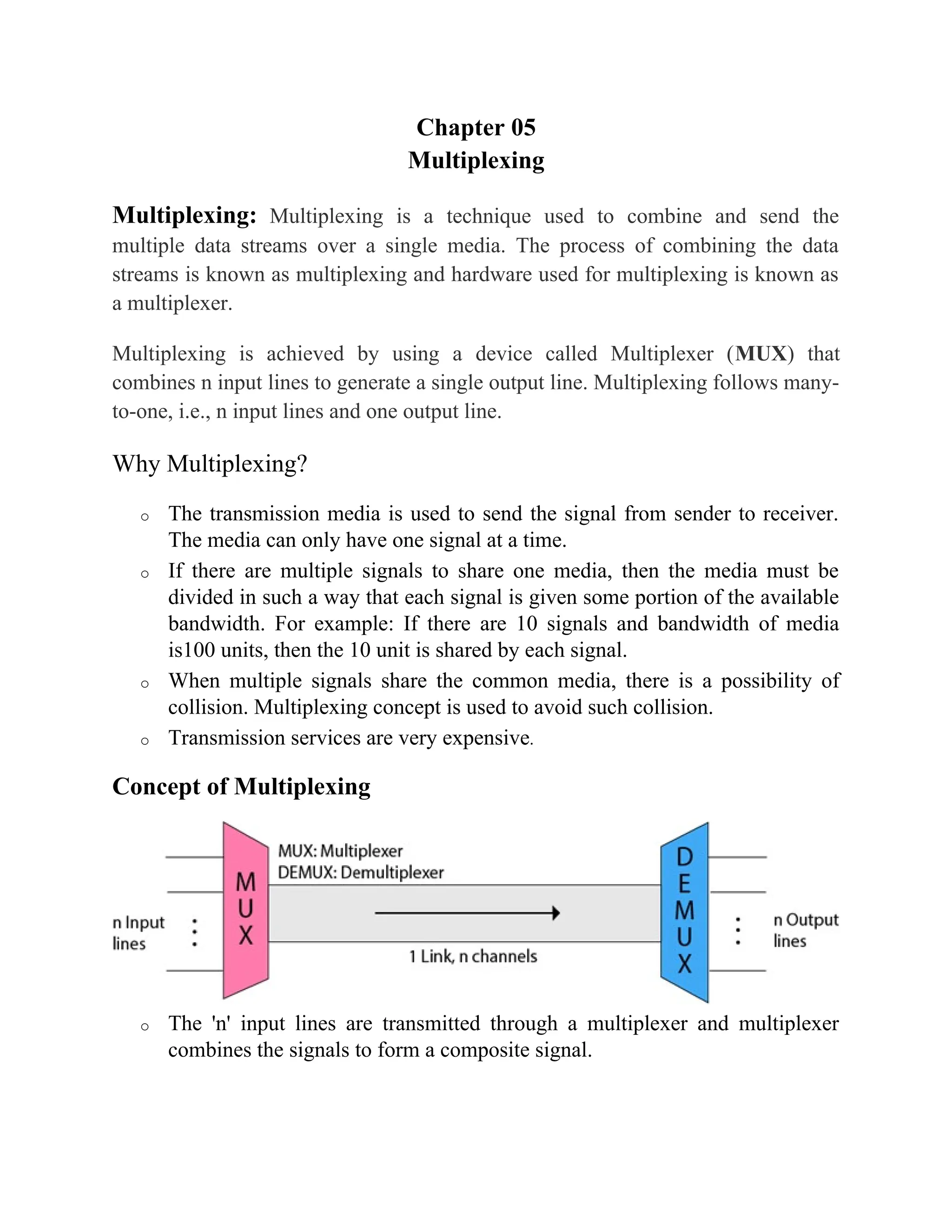
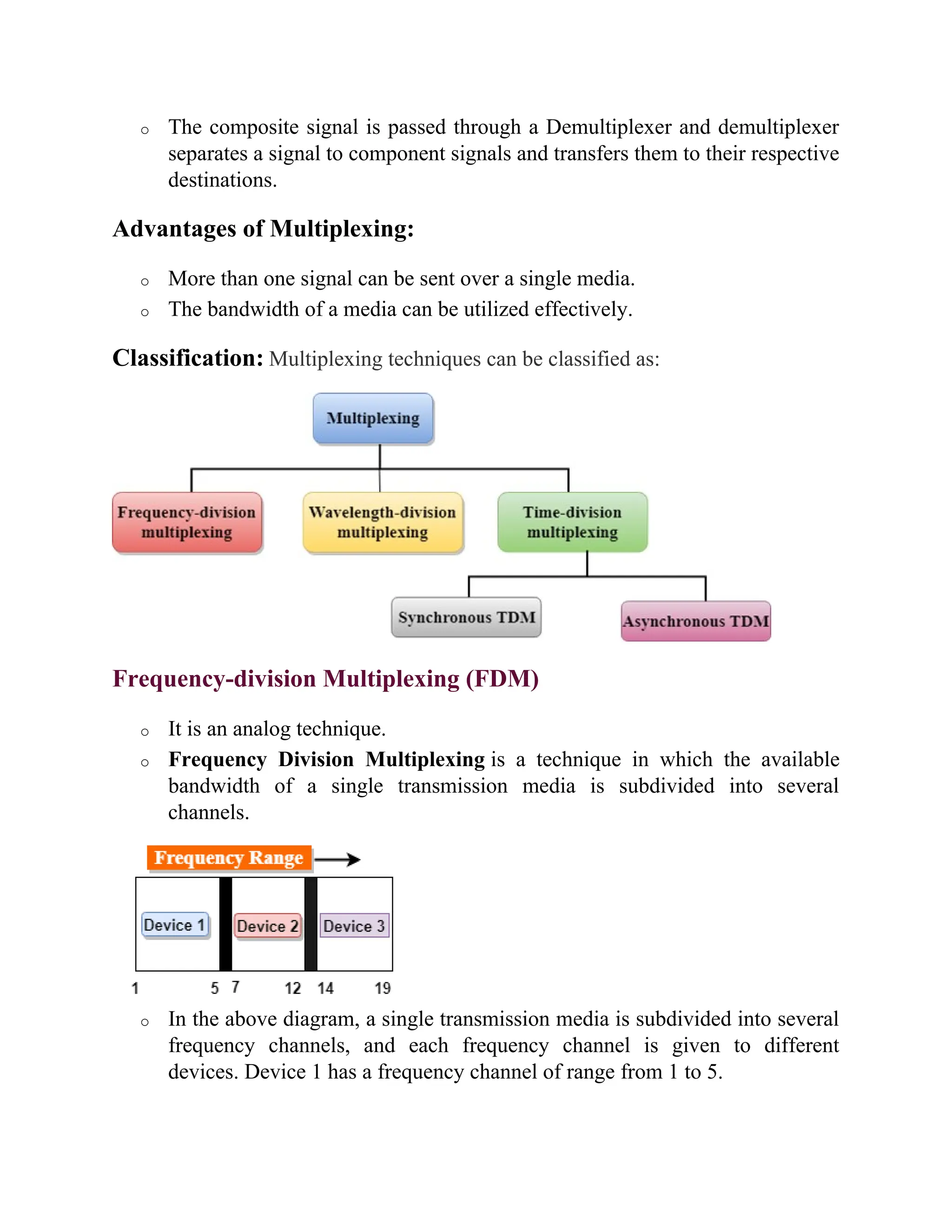
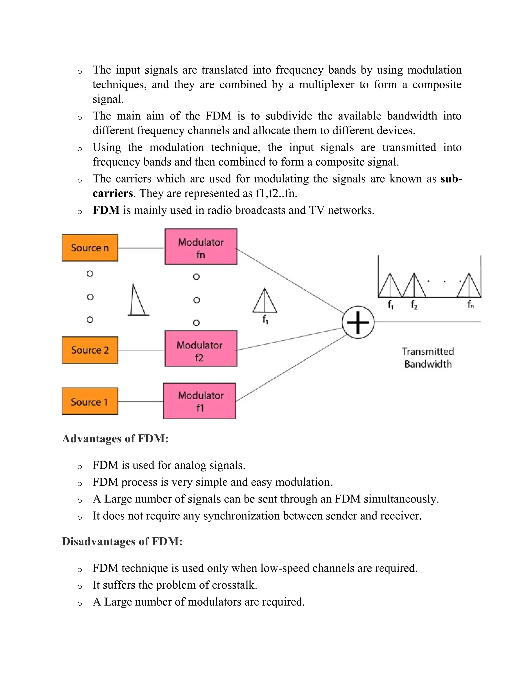
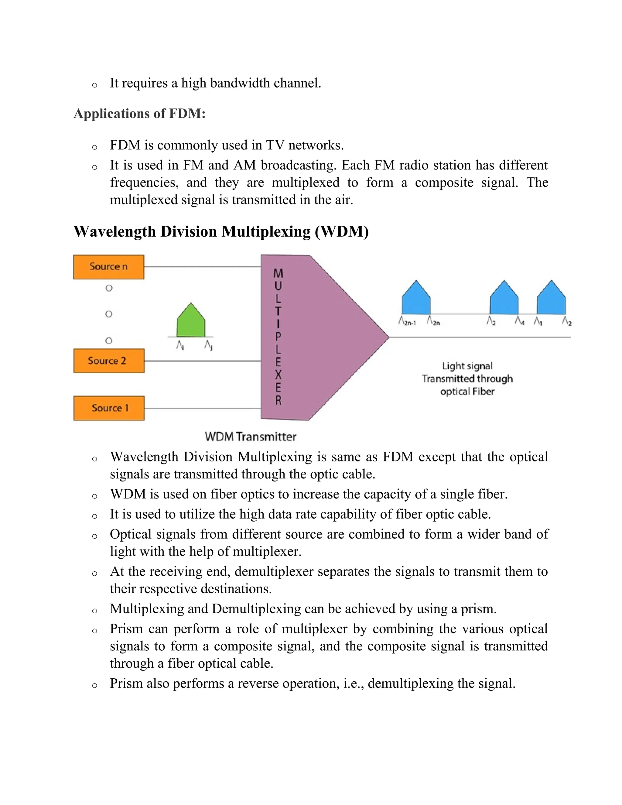
Chapter 05
Multiplexing
Multiplexing: Multiplexing is a technique used to combine and send the
multiple data streams over a single media. The process of combining the data
streams is known as multiplexing and hardware used for multiplexing is known as
a multiplexer.
Multiplexing is achieved by using a device called Multiplexer (MUX) that
combines n input lines to generate a single output line. Multiplexing follows many-
to-one, i.e., n input lines and one output line.
Why Multiplexing?
o The transmission media is used to send the signal from sender to receiver.
The media can only have one signal at a time.
o If there are multiple signals to share one media, then the media must be
divided in such a way that each signal is given some portion of the available
bandwidth. For example: If there are 10 signals and bandwidth of media
is100 units, then the 10 unit is shared by each signal.
o When multiple signals share the common media, there is a possibility of
collision. Multiplexing concept is used to avoid such collision.
o Transmission services are very expensive.
Concept of Multiplexing
o The 'n' input lines are transmitted through a multiplexer and multiplexer
combines the signals to form a composite signal.
o The composite signal is passed through a Demultiplexer and demultiplexer
separates a signal to component signals and transfers them to their respective
destinations.
Advantages of Multiplexing:
o More than one signal can be sent over a single media.
o The bandwidth of a media can be utilized effectively.
Classification: Multiplexing techniques can be classified as:
Frequency-division Multiplexing (FDM)
o It is an analog technique.
o Frequency Division Multiplexing is a technique in which the available
bandwidth of a single transmission media is subdivided into several
channels.
o In the above diagram, a single transmission media is subdivided into several
frequency channels, and each frequency channel is given to different
devices. Device 1 has a frequency channel of range from 1 to 5.
o The input signals are translated into frequency bands by using modulation
techniques, and they are combined by a multiplexer to form a composite
signal.
o The main aim of the FDM is to subdivide the available bandwidth into
different frequency channels and allocate them to different devices.
o Using the modulation technique, the input signals are transmitted into
frequency bands and then combined to form a composite signal.
o The carriers which are used for modulating the signals are known as sub-
carriers. They are represented as f1,f2..fn.
o FDM is mainly used in radio broadcasts and TV networks.
Advantages of FDM:
o FDM is used for analog signals.
o FDM process is very simple and easy modulation.
o A Large number of signals can be sent through an FDM simultaneously.
o It does not require any synchronization between sender and receiver.
Disadvantages of FDM:
o FDM technique is used only when low-speed channels are required.
o It suffers the problem of crosstalk.
o A Large number of modulators are required.
o It requires a high bandwidth channel.
Applications of FDM:
o FDM is commonly used in TV networks.
o It is used in FM and AM broadcasting. Each FM radio station has different
frequencies, and they are multiplexed to form a composite signal. The
multiplexed signal is transmitted in the air.
Wavelength Division Multiplexing (WDM)
o Wavelength Division Multiplexing is same as FDM except that the optical
signals are transmitted through the optic cable.
o WDM is used on fiber optics to increase the capacity of a single fiber.
o It is used to utilize the high data rate capability of fiber optic cable.
o Optical signals from different source are combined to form a wider band of
light with the help of multiplexer.
o At the receiving end, demultiplexer separates the signals to transmit them to
their respective destinations.
o Multiplexing and Demultiplexing can be achieved by using a prism.
o Prism can perform a role of multiplexer by combining the various optical
signals to form a composite signal, and the composite signal is transmitted
through a fiber optical cable.
o Prism also performs a reverse operation, i.e., demultiplexing the signal.
Time Division Multiplexing
o It is a digital technique.
o In Frequency Division Multiplexing Technique, all signals operate at the
same time with different frequency, but in case of Time Division
Multiplexing technique, all signals operate at the same frequency with
different time.
o In Time Division Multiplexing technique, the total time available in the
channel is distributed among different users. Therefore, each user is
allocated with different time interval known as a Time slot at which data is
to be transmitted by the sender.
o A user takes control of the channel for a fixed amount of time.
o In Time Division Multiplexing technique, data is not transmitted
simultaneously rather the data is transmitted one-by-one.
o In TDM, the signal is transmitted in the form of frames. Frames contain a
cycle of time slots in which each frame contains one or more slots dedicated
to each user.
o It can be used to multiplex both digital and analog signals but mainly used to
multiplex digital signals.
There are two types of TDM:
o Synchronous TDM
o Asynchronous TDM
Synchronous TDM
o A Synchronous TDM is a technique in which time slot is pre assigned to
every device.
o In Synchronous TDM, each device is given some time slot irrespective of
the fact that the device contains the data or not.
o If the device does not have any data, then the slot will remain empty.
o In Synchronous TDM, signals are sent in the form of frames. Time slots are
organized in the form of frames. If a device does not have data for a
particular time slot, then the empty slot will be transmitted.
o The most popular Synchronous TDM are T-1 multiplexing, ISDN
(Integrated Services Digital Network) multiplexing, and SONET
(Synchronous Optical Network) multiplexing.
o If there are n devices, then there are n slots.
Concept of Synchronous TDM
In the above figure, the Synchronous TDM technique is implemented. Each device
is allocated with some time slot. The time slots are transmitted irrespective of
whether the sender has data to send or not.
Disadvantages of Synchronous TDM:
o The capacity of the channel is not fully utilized as the empty slots are also
transmitted which is having no data. In the above figure, the first frame is
completely filled, but in the last two frames, some slots are empty.
Therefore, we can say that the capacity of the channel is not utilized
efficiently.
o The speed of the transmission media should be greater than the total speed of
the input lines. An alternative approach to the Synchronous TDM is
Asynchronous Time Division Multiplexing.
Asynchronous TDM
o An asynchronous TDM is also known as Statistical TDM.
o An asynchronous TDM is a technique in which time slots are not fixed as in
the case of Synchronous TDM. Time slots are allocated to only those
devices which have the data to send. Therefore, we can say that
Asynchronous Time Division multiplexor transmits only the data from
active workstations.
o An asynchronous TDM technique dynamically allocates the time slots to the
devices.
o In Asynchronous TDM, total speed of the input lines can be greater than the
capacity of the channel.
o Asynchronous Time Division multiplexor accepts the incoming data streams
and creates a frame that contains only data with no empty slots.
o In Asynchronous TDM, each slot contains an address part that identifies the
source of the data.
o The difference between Asynchronous TDM and Synchronous TDM is that
many slots in Synchronous TDM are unutilized, but in Asynchronous TDM,
slots are fully utilized. This leads to the smaller transmission time and
efficient utilization of the capacity of the channel.
o In Synchronous TDM, if there are n sending devices, then there are n time
slots. In Asynchronous TDM, if there are n sending devices, then there are m
time slots where m is less than n (m<n).
o The number of slots in a frame depends on the statistical analysis of the
number of input lines.
Concept of Asynchronous TDM
In the above diagram, there are 4 devices, but only two devices are sending the
data, i.e., A and C. Therefore, the data of A and C are only transmitted through the
transmission line.
Frame of above diagram can be represented as:
The above figure shows that the data part contains the address to determine the
source of the data.
Differences between TDM and FDM
Parameters TDM FDM
Full-Form The term TDM is an acronym
for Time Division
Multiplexing.
The term FDM is an acronym
for Frequency Division
Multiplexing.
Basic For all the signals it deals with,
it shares the overall timescale.
It means that it shares the time
for available signals.
For all the signals it works with,
it shares the overall frequency.
It means that it shares the
frequency for the available
signals.
Types of
Signals
It works with both- digital as
well as analog signals.
It only deals with analog
signals.
Circuitry It consists of a very simple type
of circuitry.
The circuitry, in this case, is
comparatively more complex.
Wiring Used The Chip or Wiring of TDM is
comparatively much simpler.
FDM has a comparatively much
more complex Chip or Wiring.
Conflict This technique has very low
conflict.
This technique has a
comparatively higher conflict.
Input
Required
The synchronization pulse is a
prerequisite in the case of the
The guard band is a prerequisite
in the case of the FDM
TDM technique. technique.
Interference The TDM technique has a very
low or negligible interference.
The FDM technique has a very
high level of interference.
Efficiency This technique is way more
efficient than FDM.
This technique is quite
inefficient as compared to
TDM.
What is the Difference between FDM TDM and WDM?
FDM vs. TDM vs. WDM
FDM is a transmission
technique in which
multiple data signals are
combined for
simultaneous transmission
via a shared
communication media.
TDM is a transmission
technique that allows
multiple users to send
signals over a common
channel by allocating
fixed time slot for each
user.
WDM is a transmission
technique that modulates
numerous data streams,
optical carrier signals of
varying wavelengths into
a single light beams
through a single optical
fiber.
Functionality
FDM divides the
bandwidth into smaller
frequency ranges
antransmitsser transmit
data simultaneously
through a common
channel within their
frequency range.
TDM allocates a fixed
time slot for each user
to send signals through
a common channel.
User gets the entire
bandwidth within that
time slot.
WDM combines multiple
light beams from several
channels and combine
them to a single light
beam and sends through a
fiber optic strand similar
to FDM.
Stands for
FDM stands for Frequency
Division Multiplexing.
TDM stands for Time
Division Multiplexing.
WDM stands for Wave
Length Multiplexing.
Type of Signals
FDM uses analog signals.
TDM uses digital and
analog signals.
WDM uses optical
signals.
Multilevel Multiplexing
Multilevel multiplexing is a technique used when the data rate of an input line is a
multiple of others. For example, in Figure 01, we have two inputs of 20 kbps and
three inputs of 40 kbps. The first two input lines can be multiplexed together to
provide a data rate equal to the last three. A second level of multiplexing can create
an output of 160 kbps.
20 kbps 40 kbps
20 kbps 160 kbps
40 kbps
40 kbps
40 kbps
Figure-01: Multilevel multiplexing
Multiple-Slot Allocation
Multiple-Slot Allocation Sometimes it is more efficient to allot more than one slot
in a frame to a single input line. For example, we might have an input line that has
a data rate that is a multiple of another input. In Figure- 02, the input line with a
50-kbps data rate can be given two slots in the output. We insert a serial-to-parallel
converter in the line to make two inputs out of one.
50kbps 25kbps
25kbps 125kbps
25kbps
25kbps
25kbps
Figure- 02: Multiple-Slot Allocation
IP address definition
IP stands for "Internet Protocol" which is the set of rules governing the format of
data sent via the internet or local network. An IP address is a unique address that
identifies a device on the internet or a local network.
An IP address is a string of numbers separated by periods. IP addresses are
expressed as a set of four numbers — an example address might be 192.158.1.38.
Each number in the set can range from 0 to 255. So, the full IP addressing range
goes from 0.0.0.0 to 255.255.255.255.
Classification of IP Address:
If your computer is connected to both your local network and the internet, then it
will have two IP addresses. You’ll have a private IP address locally and a public IP
address on the internet.
Private IP address: A Private IP address is used to connect your computer or
device to your home or business network. This address is normally assigned by
your network router.
Private IP addresses are in the range 40.xxx.xxx.xxx or 192.168.xxx.xxx. An
example of a private IP address is 192.168.1.1.
Public IP address: Public IP address is used to connect your home or
business network to the internet. This address is assigned by your internet service
provider (ISP).
IPv4:
IPv4 is the most widely used version of the Internet Protocol. It defines IP
addresses in a 32-bit format, which looks like 123.123.123.123. Each three-digit
section can include a number from 0 to 255, which means the total number of IPv4
addresses available is 4,294,967,296 (256 x 256 x 256 x 256 or 2^32).
Each computer or device connected to the Internet must have a unique IP
address in order to communicate with other systems on the Internet. Because the
The input with a 50kbps data
rate has two slots in each
frame
number of systems connected to the Internet is quickly approaching the number of
available IP addresses, IPv4 addresses are predicted to run out soon. When you
consider that there are over 6 billion people in the world and many people have
more than one system connected to the Internet (for example, at home, school,
work, etc.), it is not surprising that roughly 4.3 billion addresses is not enough.
Classes of IPV4:
In the IPv4 IP address space, there are five classes: A, B, C, D and E. Each class
has a specific range of IP addresses (and ultimately dictates the number of devices
you can have on your network). Primarily, class A, B and C are used by the
majority of devices on the Internet. Class D and class E are for special uses.
Class A Address
The first bit of the first octet is always set to 0 (zero). Thus the first octet ranges
from 1 – 127, i.e.
Class A addresses only include IP starting from 1.x.x.x to 126.x.x.x only. The IP
range 127.x.x.x is reserved for loopback IP addresses.
The default subnet mask for Class A IP address is 255.0.0.0 which implies that
Class A addressing can have 126 networks (27
-2) and 16777214 hosts (224
-2).
Class A IP address format is
thus: 0NNNNNNN.HHHHHHHH.HHHHHHHH.HHHHHHHH
Class B Address
An IP address which belongs to class B has the first two bits in the first octet set
to 10, i.e.
Class B IP Addresses range from 128.0.x.x to 191.255.x.x. The default subnet
mask for Class B is 255.255.x.x.
Class B has 16384 (214
) Network addresses and 65534 (216
-2) Host addresses.
Class B IP address format
is: 10NNNNNN.NNNNNNNN.HHHHHHHH.HHHHHHHH
Class C Address
The first octet of Class C IP address has its first 3 bits set to 110, that is −
Class C IP addresses range from 192.0.0.x to 223.255.255.x. The default subnet
mask for Class C is 255.255.255.x.
Class C gives 2097152 (221
) Network addresses and 254 (28
-2) Host addresses.
Class C IP address format
is: 110NNNNN.NNNNNNNN.NNNNNNNN.HHHHHHHH
Class D Address
Very first four bits of the first octet in Class D IP addresses are set to 1110, giving
a range of −
Class D has IP address range from 224.0.0.0 to 239.255.255.255. Class D is
reserved for Multicasting. In multicasting data is not designed for a particular
host, that is why there is no need to extract host address from the IP address, and
Class D does not have any subnet mask.
Class E Address
This IP Class is reserved for experimental purposes only for R&D (Research and
Development) or Study. IP addresses in this class ranges from 240.0.0.0 to
255.255.255.254. Like Class D, this class too is not equipped with any subnet
mask.
IP Header Classes:
Class
Address
Range
Subnet
masking
Example
IP
Leading
bits
Max number
of networks
Application
IP
Class
A
1 to 126 255.0.0.0 1.1.1.1 8 128
Used for large number of
hosts.
IP
Class
B
128 to 191 255.255.0.0 128.1.1.1 16 16384
Used for media size
network.
IP
Class
C
192 to 223 255.255.255.0 192.1.11. 24 2097157
Used for local area
network.
IP
Class
D
224 to 239 NA NA NA NA Reserve for multi-tasking.
IP
Class
240 to 254 NA NA NA NA This class is reserved for
research and Development
Class
Address
Range
Subnet
masking
Example
IP
Leading
bits
Max number
of networks
Application
E Purposes.
NRZ
In telecommunication, a non-return-to-zero (NRZ) line code is a binary code in
which ones are represented by one significant condition, usually a positive voltage,
while zeros are represented by some other significant condition, usually a negative
voltage, with no other neutral or rest condition.
Bipolar
The bipolar encoding scheme defines three voltage methods: positive, negative,
and zero. In the Bipolar encoding scheme, zero levels define binary 0, and binary 1
is described by rotating positive and negative voltages.
Assume the first 1 bit is described by positive amplitude. A negative voltage means
the second 1 bit; the positive amplitude explains the third 1 bit. This rotation can
also appear even when the 1 bit are not successive.
There are three types of Bipolar which are as follows −
AMI
AMI means Bipolar Alternate Mark Inversion. It is the elementary method of
bipolar encoding. Here the word 'mark' comes from telegraphy defines 1. AMI
defines alternate 1 inversion.
In the Bipolar AMI encoding scheme, 0 bit is defined by zero levels and 1 bit is
described by rotating positive and negative voltages.
A variation of bipolar AMI is also known as pseudo ternary because binary 0
alternates between +ve and –ve voltages. By reversing each appearance of a 1,
bipolar AMI achieves two things, the DC component is zero, and the second stay
synchronized. Still, long strings of the synchronization method are not ensured.
Manchester Encoding:
In data communication, different encoding techniques are introduced for security
of data and fast transmission. Manchester encoding is one such digital encoding
technique. It is quite different from other digital encoding techniques because each
data bit length is fixed by default. The bit state is determined according to the
transition direction. Different systems represent bit status in different ways, but
most systems represent 1 bit against low to high transition and 0 bit for high to low
transition.
Signaling synchronization is the major advantage of Manchester encoding.
Synchronization of signals provides higher reliability with the same data rate
compared to other methods. But programmers should note that Manchester
encoding has some disadvantages too. For example, the Manchester encoded signal
consumes more bandwidth than the original signal.
Manchester encoding has the following characteristics:
 Each bit is transmitted in fixed time.
 A ‘1’ is noted when high to low transition occurs; 0 is expressed when a low
to high transition is made.
 The transition that is used to note 1 or 0 accurately occurs at the mid-point of
a period.
Chapter-05- Multiplexing , Advantages of Multiplexing

Chapter-05- Multiplexing , Advantages of Multiplexing

  • 1.
    Chapter 05 Multiplexing Multiplexing: Multiplexingis a technique used to combine and send the multiple data streams over a single media. The process of combining the data streams is known as multiplexing and hardware used for multiplexing is known as a multiplexer. Multiplexing is achieved by using a device called Multiplexer (MUX) that combines n input lines to generate a single output line. Multiplexing follows many- to-one, i.e., n input lines and one output line. Why Multiplexing? o The transmission media is used to send the signal from sender to receiver. The media can only have one signal at a time. o If there are multiple signals to share one media, then the media must be divided in such a way that each signal is given some portion of the available bandwidth. For example: If there are 10 signals and bandwidth of media is100 units, then the 10 unit is shared by each signal. o When multiple signals share the common media, there is a possibility of collision. Multiplexing concept is used to avoid such collision. o Transmission services are very expensive. Concept of Multiplexing o The 'n' input lines are transmitted through a multiplexer and multiplexer combines the signals to form a composite signal.
  • 2.
    o The compositesignal is passed through a Demultiplexer and demultiplexer separates a signal to component signals and transfers them to their respective destinations. Advantages of Multiplexing: o More than one signal can be sent over a single media. o The bandwidth of a media can be utilized effectively. Classification: Multiplexing techniques can be classified as: Frequency-division Multiplexing (FDM) o It is an analog technique. o Frequency Division Multiplexing is a technique in which the available bandwidth of a single transmission media is subdivided into several channels. o In the above diagram, a single transmission media is subdivided into several frequency channels, and each frequency channel is given to different devices. Device 1 has a frequency channel of range from 1 to 5.
  • 3.
    o The inputsignals are translated into frequency bands by using modulation techniques, and they are combined by a multiplexer to form a composite signal. o The main aim of the FDM is to subdivide the available bandwidth into different frequency channels and allocate them to different devices. o Using the modulation technique, the input signals are transmitted into frequency bands and then combined to form a composite signal. o The carriers which are used for modulating the signals are known as sub- carriers. They are represented as f1,f2..fn. o FDM is mainly used in radio broadcasts and TV networks. Advantages of FDM: o FDM is used for analog signals. o FDM process is very simple and easy modulation. o A Large number of signals can be sent through an FDM simultaneously. o It does not require any synchronization between sender and receiver. Disadvantages of FDM: o FDM technique is used only when low-speed channels are required. o It suffers the problem of crosstalk. o A Large number of modulators are required.
  • 4.
    o It requiresa high bandwidth channel. Applications of FDM: o FDM is commonly used in TV networks. o It is used in FM and AM broadcasting. Each FM radio station has different frequencies, and they are multiplexed to form a composite signal. The multiplexed signal is transmitted in the air. Wavelength Division Multiplexing (WDM) o Wavelength Division Multiplexing is same as FDM except that the optical signals are transmitted through the optic cable. o WDM is used on fiber optics to increase the capacity of a single fiber. o It is used to utilize the high data rate capability of fiber optic cable. o Optical signals from different source are combined to form a wider band of light with the help of multiplexer. o At the receiving end, demultiplexer separates the signals to transmit them to their respective destinations. o Multiplexing and Demultiplexing can be achieved by using a prism. o Prism can perform a role of multiplexer by combining the various optical signals to form a composite signal, and the composite signal is transmitted through a fiber optical cable. o Prism also performs a reverse operation, i.e., demultiplexing the signal.
  • 5.
    Time Division Multiplexing oIt is a digital technique. o In Frequency Division Multiplexing Technique, all signals operate at the same time with different frequency, but in case of Time Division Multiplexing technique, all signals operate at the same frequency with different time. o In Time Division Multiplexing technique, the total time available in the channel is distributed among different users. Therefore, each user is allocated with different time interval known as a Time slot at which data is to be transmitted by the sender. o A user takes control of the channel for a fixed amount of time. o In Time Division Multiplexing technique, data is not transmitted simultaneously rather the data is transmitted one-by-one. o In TDM, the signal is transmitted in the form of frames. Frames contain a cycle of time slots in which each frame contains one or more slots dedicated to each user. o It can be used to multiplex both digital and analog signals but mainly used to multiplex digital signals. There are two types of TDM: o Synchronous TDM o Asynchronous TDM Synchronous TDM
  • 6.
    o A SynchronousTDM is a technique in which time slot is pre assigned to every device. o In Synchronous TDM, each device is given some time slot irrespective of the fact that the device contains the data or not. o If the device does not have any data, then the slot will remain empty. o In Synchronous TDM, signals are sent in the form of frames. Time slots are organized in the form of frames. If a device does not have data for a particular time slot, then the empty slot will be transmitted. o The most popular Synchronous TDM are T-1 multiplexing, ISDN (Integrated Services Digital Network) multiplexing, and SONET (Synchronous Optical Network) multiplexing. o If there are n devices, then there are n slots. Concept of Synchronous TDM
  • 7.
    In the abovefigure, the Synchronous TDM technique is implemented. Each device is allocated with some time slot. The time slots are transmitted irrespective of whether the sender has data to send or not. Disadvantages of Synchronous TDM: o The capacity of the channel is not fully utilized as the empty slots are also transmitted which is having no data. In the above figure, the first frame is completely filled, but in the last two frames, some slots are empty. Therefore, we can say that the capacity of the channel is not utilized efficiently. o The speed of the transmission media should be greater than the total speed of the input lines. An alternative approach to the Synchronous TDM is Asynchronous Time Division Multiplexing. Asynchronous TDM o An asynchronous TDM is also known as Statistical TDM. o An asynchronous TDM is a technique in which time slots are not fixed as in the case of Synchronous TDM. Time slots are allocated to only those devices which have the data to send. Therefore, we can say that Asynchronous Time Division multiplexor transmits only the data from active workstations. o An asynchronous TDM technique dynamically allocates the time slots to the devices.
  • 8.
    o In AsynchronousTDM, total speed of the input lines can be greater than the capacity of the channel. o Asynchronous Time Division multiplexor accepts the incoming data streams and creates a frame that contains only data with no empty slots. o In Asynchronous TDM, each slot contains an address part that identifies the source of the data. o The difference between Asynchronous TDM and Synchronous TDM is that many slots in Synchronous TDM are unutilized, but in Asynchronous TDM, slots are fully utilized. This leads to the smaller transmission time and efficient utilization of the capacity of the channel. o In Synchronous TDM, if there are n sending devices, then there are n time slots. In Asynchronous TDM, if there are n sending devices, then there are m time slots where m is less than n (m<n). o The number of slots in a frame depends on the statistical analysis of the number of input lines. Concept of Asynchronous TDM In the above diagram, there are 4 devices, but only two devices are sending the data, i.e., A and C. Therefore, the data of A and C are only transmitted through the transmission line. Frame of above diagram can be represented as:
  • 9.
    The above figureshows that the data part contains the address to determine the source of the data. Differences between TDM and FDM Parameters TDM FDM Full-Form The term TDM is an acronym for Time Division Multiplexing. The term FDM is an acronym for Frequency Division Multiplexing. Basic For all the signals it deals with, it shares the overall timescale. It means that it shares the time for available signals. For all the signals it works with, it shares the overall frequency. It means that it shares the frequency for the available signals. Types of Signals It works with both- digital as well as analog signals. It only deals with analog signals. Circuitry It consists of a very simple type of circuitry. The circuitry, in this case, is comparatively more complex. Wiring Used The Chip or Wiring of TDM is comparatively much simpler. FDM has a comparatively much more complex Chip or Wiring. Conflict This technique has very low conflict. This technique has a comparatively higher conflict. Input Required The synchronization pulse is a prerequisite in the case of the The guard band is a prerequisite in the case of the FDM
  • 10.
    TDM technique. technique. InterferenceThe TDM technique has a very low or negligible interference. The FDM technique has a very high level of interference. Efficiency This technique is way more efficient than FDM. This technique is quite inefficient as compared to TDM. What is the Difference between FDM TDM and WDM? FDM vs. TDM vs. WDM FDM is a transmission technique in which multiple data signals are combined for simultaneous transmission via a shared communication media. TDM is a transmission technique that allows multiple users to send signals over a common channel by allocating fixed time slot for each user. WDM is a transmission technique that modulates numerous data streams, optical carrier signals of varying wavelengths into a single light beams through a single optical fiber. Functionality FDM divides the bandwidth into smaller frequency ranges antransmitsser transmit data simultaneously through a common channel within their frequency range. TDM allocates a fixed time slot for each user to send signals through a common channel. User gets the entire bandwidth within that time slot. WDM combines multiple light beams from several channels and combine them to a single light beam and sends through a fiber optic strand similar to FDM. Stands for
  • 11.
    FDM stands forFrequency Division Multiplexing. TDM stands for Time Division Multiplexing. WDM stands for Wave Length Multiplexing. Type of Signals FDM uses analog signals. TDM uses digital and analog signals. WDM uses optical signals. Multilevel Multiplexing Multilevel multiplexing is a technique used when the data rate of an input line is a multiple of others. For example, in Figure 01, we have two inputs of 20 kbps and three inputs of 40 kbps. The first two input lines can be multiplexed together to provide a data rate equal to the last three. A second level of multiplexing can create an output of 160 kbps. 20 kbps 40 kbps 20 kbps 160 kbps 40 kbps 40 kbps 40 kbps Figure-01: Multilevel multiplexing Multiple-Slot Allocation Multiple-Slot Allocation Sometimes it is more efficient to allot more than one slot in a frame to a single input line. For example, we might have an input line that has a data rate that is a multiple of another input. In Figure- 02, the input line with a 50-kbps data rate can be given two slots in the output. We insert a serial-to-parallel converter in the line to make two inputs out of one.
  • 12.
    50kbps 25kbps 25kbps 125kbps 25kbps 25kbps 25kbps Figure-02: Multiple-Slot Allocation IP address definition IP stands for "Internet Protocol" which is the set of rules governing the format of data sent via the internet or local network. An IP address is a unique address that identifies a device on the internet or a local network. An IP address is a string of numbers separated by periods. IP addresses are expressed as a set of four numbers — an example address might be 192.158.1.38. Each number in the set can range from 0 to 255. So, the full IP addressing range goes from 0.0.0.0 to 255.255.255.255. Classification of IP Address: If your computer is connected to both your local network and the internet, then it will have two IP addresses. You’ll have a private IP address locally and a public IP address on the internet. Private IP address: A Private IP address is used to connect your computer or device to your home or business network. This address is normally assigned by your network router. Private IP addresses are in the range 40.xxx.xxx.xxx or 192.168.xxx.xxx. An example of a private IP address is 192.168.1.1. Public IP address: Public IP address is used to connect your home or business network to the internet. This address is assigned by your internet service provider (ISP). IPv4: IPv4 is the most widely used version of the Internet Protocol. It defines IP addresses in a 32-bit format, which looks like 123.123.123.123. Each three-digit section can include a number from 0 to 255, which means the total number of IPv4 addresses available is 4,294,967,296 (256 x 256 x 256 x 256 or 2^32). Each computer or device connected to the Internet must have a unique IP address in order to communicate with other systems on the Internet. Because the The input with a 50kbps data rate has two slots in each frame
  • 13.
    number of systemsconnected to the Internet is quickly approaching the number of available IP addresses, IPv4 addresses are predicted to run out soon. When you consider that there are over 6 billion people in the world and many people have more than one system connected to the Internet (for example, at home, school, work, etc.), it is not surprising that roughly 4.3 billion addresses is not enough. Classes of IPV4: In the IPv4 IP address space, there are five classes: A, B, C, D and E. Each class has a specific range of IP addresses (and ultimately dictates the number of devices you can have on your network). Primarily, class A, B and C are used by the majority of devices on the Internet. Class D and class E are for special uses. Class A Address The first bit of the first octet is always set to 0 (zero). Thus the first octet ranges from 1 – 127, i.e. Class A addresses only include IP starting from 1.x.x.x to 126.x.x.x only. The IP range 127.x.x.x is reserved for loopback IP addresses. The default subnet mask for Class A IP address is 255.0.0.0 which implies that Class A addressing can have 126 networks (27 -2) and 16777214 hosts (224 -2). Class A IP address format is thus: 0NNNNNNN.HHHHHHHH.HHHHHHHH.HHHHHHHH Class B Address An IP address which belongs to class B has the first two bits in the first octet set to 10, i.e. Class B IP Addresses range from 128.0.x.x to 191.255.x.x. The default subnet mask for Class B is 255.255.x.x. Class B has 16384 (214 ) Network addresses and 65534 (216 -2) Host addresses. Class B IP address format is: 10NNNNNN.NNNNNNNN.HHHHHHHH.HHHHHHHH Class C Address The first octet of Class C IP address has its first 3 bits set to 110, that is −
  • 14.
    Class C IPaddresses range from 192.0.0.x to 223.255.255.x. The default subnet mask for Class C is 255.255.255.x. Class C gives 2097152 (221 ) Network addresses and 254 (28 -2) Host addresses. Class C IP address format is: 110NNNNN.NNNNNNNN.NNNNNNNN.HHHHHHHH Class D Address Very first four bits of the first octet in Class D IP addresses are set to 1110, giving a range of − Class D has IP address range from 224.0.0.0 to 239.255.255.255. Class D is reserved for Multicasting. In multicasting data is not designed for a particular host, that is why there is no need to extract host address from the IP address, and Class D does not have any subnet mask. Class E Address This IP Class is reserved for experimental purposes only for R&D (Research and Development) or Study. IP addresses in this class ranges from 240.0.0.0 to 255.255.255.254. Like Class D, this class too is not equipped with any subnet mask. IP Header Classes: Class Address Range Subnet masking Example IP Leading bits Max number of networks Application IP Class A 1 to 126 255.0.0.0 1.1.1.1 8 128 Used for large number of hosts. IP Class B 128 to 191 255.255.0.0 128.1.1.1 16 16384 Used for media size network. IP Class C 192 to 223 255.255.255.0 192.1.11. 24 2097157 Used for local area network. IP Class D 224 to 239 NA NA NA NA Reserve for multi-tasking. IP Class 240 to 254 NA NA NA NA This class is reserved for research and Development
  • 15.
    Class Address Range Subnet masking Example IP Leading bits Max number of networks Application EPurposes. NRZ In telecommunication, a non-return-to-zero (NRZ) line code is a binary code in which ones are represented by one significant condition, usually a positive voltage, while zeros are represented by some other significant condition, usually a negative voltage, with no other neutral or rest condition. Bipolar The bipolar encoding scheme defines three voltage methods: positive, negative, and zero. In the Bipolar encoding scheme, zero levels define binary 0, and binary 1 is described by rotating positive and negative voltages. Assume the first 1 bit is described by positive amplitude. A negative voltage means the second 1 bit; the positive amplitude explains the third 1 bit. This rotation can also appear even when the 1 bit are not successive. There are three types of Bipolar which are as follows − AMI AMI means Bipolar Alternate Mark Inversion. It is the elementary method of bipolar encoding. Here the word 'mark' comes from telegraphy defines 1. AMI defines alternate 1 inversion. In the Bipolar AMI encoding scheme, 0 bit is defined by zero levels and 1 bit is described by rotating positive and negative voltages.
  • 16.
    A variation ofbipolar AMI is also known as pseudo ternary because binary 0 alternates between +ve and –ve voltages. By reversing each appearance of a 1, bipolar AMI achieves two things, the DC component is zero, and the second stay synchronized. Still, long strings of the synchronization method are not ensured. Manchester Encoding: In data communication, different encoding techniques are introduced for security of data and fast transmission. Manchester encoding is one such digital encoding technique. It is quite different from other digital encoding techniques because each data bit length is fixed by default. The bit state is determined according to the transition direction. Different systems represent bit status in different ways, but most systems represent 1 bit against low to high transition and 0 bit for high to low transition. Signaling synchronization is the major advantage of Manchester encoding. Synchronization of signals provides higher reliability with the same data rate compared to other methods. But programmers should note that Manchester encoding has some disadvantages too. For example, the Manchester encoded signal consumes more bandwidth than the original signal. Manchester encoding has the following characteristics:  Each bit is transmitted in fixed time.  A ‘1’ is noted when high to low transition occurs; 0 is expressed when a low to high transition is made.  The transition that is used to note 1 or 0 accurately occurs at the mid-point of a period.