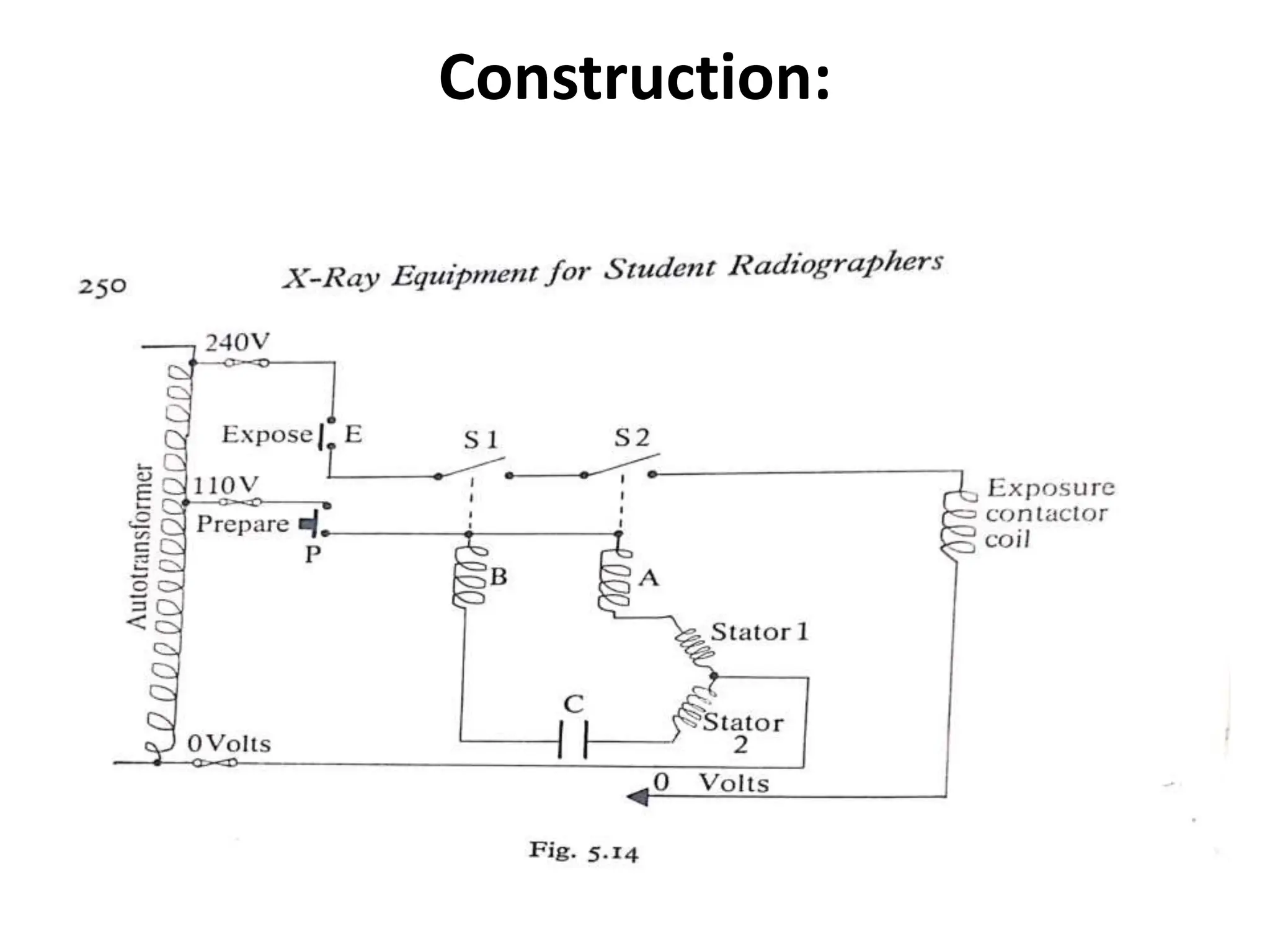
Factors which will extend the useful life of an
X-ray tube
• When an x-ray tube is in use, it is subjected to
considerable strain.
• This strain causes wear which in time leads to
a total tube failure or a gradual deterioration
in X-ray output and an increase in image un-
sharpness
• This progresses until the deterioration reaches
an unacceptable level and the tube must be
replaced.
The tube manufacturers, the equipment
suppliers and the radiographers can extend
the useful working life of an x-ray tube by:-
• Attention to design
• Care in manufacture
• Selection of a tube suitable for the work it is
to perform.
• Correct installation and adjustment
• Careful handling
• Knowledge of its operation
• Good radiographic practice
Tube selection
• It is important that the tube selected is rated
highly enough to withstand the demands put
upon it.
• It must have a very large anode heat capacity if
the work to be undertaken necessitates a very
high loading so that it will not need to be
operated near its maximum loading.
• Frequent loading over those limits shortens the
life of the tube.
Good radiographic practice
Prevention of damage to the x-ray tube anode from the
generation of excessive heat by:-
• Avoiding unnecessary high tube current or use of fine
focus when the radiographic examination does not
require it.
• This will result in exposure loading approaching the
maximum permissible loading particularly if
exposures are repeated without adequate cooling time
between them.
• Using a ‘run-up’ procedure before a very large
injection of heat is applied to a cold anode.
• Failure to do this may result in cracking of the
target disc through differential expansion, the
result of a sudden application of greater heat
on the surface of a cold anode disc.
Faults in X-ray Tubes
• With use, the X-ray tubes are bound to undergo
changes which can be likened to a process of
aging, and may also develop faults as a result of
misuse which is either mechanical or electrical.
• They can develop in any part of the tube and
wherever their origin they will affect the
operation of the tube as a whole.
• The locations can be as follows:
-The glass envelop
-The anode, the rotor, the stator windings
-The filament
-Vacuum- this is not a part but it is certainly a
feature of the tube which has been shown to
be most important
Faults in the glass envelop
• After an extensive long use of the X-ray tube,
the color of the glass changes. This is as a
result of constant exposure to radiation.
• This indicates how much work the tube has
done (and is observed by an expert because
the radiographer will not be able to see the
color of the glass insert).
• Formation of a mirror surface on the inside of
the glass envelop is an indicator of misuse.
• Heavy exposures results in vaporization of the
metal parts of the tube because of high
temperatures.
• The vaporized tungsten is deposited as a thin
layer on the inside of the glass envelop,
producing a mirror-like reflecting surface.
• The glass of the x-ray tube is susceptible to
careless handling.
• This means in practice, the X-ray unit should
not be mishandled.
Faults in the anode, the rotor and stator windings
The anode
• Every exposure heats the target area to a high
temperature and on a short exposure there is
a great difference between the temperature
on the surface bombarded by the electrons
and the depth of the tungsten.
• This leads to an effect called ‘crazing of the
target track’ or erosion of the target track.
This roughening of the surface is worse in a tube
that is maltreated by:
• Being loaded above the safe rating values and
• Being used without attention to the possibility of
overheating the anode by repeated exposures
which individually are within safe rating limits.
• The roughening will affect sharpness of outline in
the radiographic image; it will also reduce the
radiation output for the hillocks of the roughness
in the tungsten acts as filters and reduce the
intensity of radiation leaving the tube.
• Overheating may eventually distort the anode
disc in a rotating anode and then the anode
rotates with a wobble. This means a wavering X-
ray source so that the tube fails to produce
satisfactory images.
The rotor and its bearing
• The most important is wear in the bearings which
is a sign of deterioration of the X-ray tube. The
state of the bearings is so vital to the smooth
rotation of the anode and its speed.
• Perfection in the anode’s rotation is extremely
important to radiographic image formation and
to the perfection of the tube against the heat
each exposure produces.
Faults in the filament
Failure of the filament to heat when its circuit is
energized may be due to:
(i) a break in the filament itself, or
(ii) a fault in the circuit which supplies it with power.
• Since filament is heated for every exposure
and the heat vaporizes tungsten from it, the
filament as it becomes older and thinner.
• Even if the X-ray tube is tenderly handled to
protect it from mechanical damage and
carefully loaded within normal limits, it is clear
that after long use, the filament may become
so thin as to break.
• It is then not possible to use the X-ray tube.
• This wearing of the filament takes place more
rapidly if the tube is always loaded at high mA
which requires greater filament heat and thus
shortens its life.
• Filament life can be extended during use of the
tube if the filament is energized only for the
shortest possible periods; this means switching
on the filament supply only when necessary and
keeping the exposure button on ‘prepare’ for no
longer than the shortest possible time.
INTERLOCKING CIRCUITS
• An interlock is designed to ensure that an
action(s) cannot take place until permitted to
do so by another quite separate controlling
unit.
• Interlocks protect the X-ray tube from
overload during radiographic exposure.
• The X-ray tube load depends upon the
combination of kilovoltage, tube current and
time.
• The heating effect of the load upon tube
target may be great enough to damage it
when high tube currents and high KV are
employed.
Uses:
• Are devices intended to protect the X-ray tube
• Prevent an exposure from being made in
circumstances which would result in
overheating of the target.
Controlling actions of interlocks in
X-ray equipment
1. Permitting components to reach optimum
performance before they are used e.g.:
• The tube filament must reach its correct
temperature before an exposure can be
commenced, otherwise the MA value will not be
as set.
• The anode must be full rotated before an
exposure is made, otherwise all the heat is
supplied to one area which may cause melting of
the target area with consequent release of gas.
2. Avoiding damage should a component
malfunction e.g.
• An exposure must not be permitted if the anode
is not rotating at its correct speed.
• A braking system to rapidly reduce the rotating
speed.
3. Prevent overheating of a part or whole of the X-
ray tube e.g. overload protection of the tube.
4. Controlling of X-radiation e.g. the screening
timing terminating fluoroscopy.
5. Preventing injury to person or damage to
equipment by collision e.g. the tilting table
motor drive cuts out when collision with the
floor occurs and the movement is not allowed
to continue.
Principle of operation of interlocks
• The I.C. have several switches between the
time and the exposure contactor switch.
• These switches can be used to close or open
the timer circuits, if any of the switches is
open, the timer circuit will not be complete.
• Therefore no exposure will take place.
Interlock In The Tube Stator Circuits
• This interlock ensures that an exposure does
not occur when the anode is stationary or
rotating at a lower speed – than expected.
Construction:
• When the preparation button P is pressed, the
circuit of the stator windings is complete. This
initiates the rotation of the anode. At the
same time, the relay coils A and B are
energized, thereby causing contacts S1 and S2
to close. When the exposure button E is
pressed, the circuit containing the exposure
contactor coil is completed, exposure can now
start.
• However, should there be any effects (e.g. cable
damage) of the stator supply, and consequently,
the associated relay coil will not be energized and
associated switch will remain open.
• Since the two contacts are in series with each
other, if any of them is opened, the circuit to the
exposure contactor coil will not be completed.
This means that no exposure will occur even
when the exposure button is pressed.

7. Faults in Xray tube (1).ppt

  • 1.
    Factors which willextend the useful life of an X-ray tube • When an x-ray tube is in use, it is subjected to considerable strain. • This strain causes wear which in time leads to a total tube failure or a gradual deterioration in X-ray output and an increase in image un- sharpness • This progresses until the deterioration reaches an unacceptable level and the tube must be replaced.
  • 2.
    The tube manufacturers,the equipment suppliers and the radiographers can extend the useful working life of an x-ray tube by:- • Attention to design • Care in manufacture • Selection of a tube suitable for the work it is to perform.
  • 3.
    • Correct installationand adjustment • Careful handling • Knowledge of its operation • Good radiographic practice
  • 4.
    Tube selection • Itis important that the tube selected is rated highly enough to withstand the demands put upon it. • It must have a very large anode heat capacity if the work to be undertaken necessitates a very high loading so that it will not need to be operated near its maximum loading. • Frequent loading over those limits shortens the life of the tube.
  • 5.
    Good radiographic practice Preventionof damage to the x-ray tube anode from the generation of excessive heat by:- • Avoiding unnecessary high tube current or use of fine focus when the radiographic examination does not require it. • This will result in exposure loading approaching the maximum permissible loading particularly if exposures are repeated without adequate cooling time between them.
  • 6.
    • Using a‘run-up’ procedure before a very large injection of heat is applied to a cold anode. • Failure to do this may result in cracking of the target disc through differential expansion, the result of a sudden application of greater heat on the surface of a cold anode disc.
  • 7.
    Faults in X-rayTubes • With use, the X-ray tubes are bound to undergo changes which can be likened to a process of aging, and may also develop faults as a result of misuse which is either mechanical or electrical. • They can develop in any part of the tube and wherever their origin they will affect the operation of the tube as a whole. • The locations can be as follows: -The glass envelop
  • 8.
    -The anode, therotor, the stator windings -The filament -Vacuum- this is not a part but it is certainly a feature of the tube which has been shown to be most important Faults in the glass envelop • After an extensive long use of the X-ray tube, the color of the glass changes. This is as a result of constant exposure to radiation.
  • 9.
    • This indicateshow much work the tube has done (and is observed by an expert because the radiographer will not be able to see the color of the glass insert). • Formation of a mirror surface on the inside of the glass envelop is an indicator of misuse. • Heavy exposures results in vaporization of the metal parts of the tube because of high temperatures.
  • 10.
    • The vaporizedtungsten is deposited as a thin layer on the inside of the glass envelop, producing a mirror-like reflecting surface. • The glass of the x-ray tube is susceptible to careless handling. • This means in practice, the X-ray unit should not be mishandled.
  • 11.
    Faults in theanode, the rotor and stator windings The anode • Every exposure heats the target area to a high temperature and on a short exposure there is a great difference between the temperature on the surface bombarded by the electrons and the depth of the tungsten. • This leads to an effect called ‘crazing of the target track’ or erosion of the target track.
  • 12.
    This roughening ofthe surface is worse in a tube that is maltreated by: • Being loaded above the safe rating values and • Being used without attention to the possibility of overheating the anode by repeated exposures which individually are within safe rating limits. • The roughening will affect sharpness of outline in the radiographic image; it will also reduce the radiation output for the hillocks of the roughness in the tungsten acts as filters and reduce the intensity of radiation leaving the tube.
  • 13.
    • Overheating mayeventually distort the anode disc in a rotating anode and then the anode rotates with a wobble. This means a wavering X- ray source so that the tube fails to produce satisfactory images. The rotor and its bearing • The most important is wear in the bearings which is a sign of deterioration of the X-ray tube. The state of the bearings is so vital to the smooth rotation of the anode and its speed.
  • 14.
    • Perfection inthe anode’s rotation is extremely important to radiographic image formation and to the perfection of the tube against the heat each exposure produces. Faults in the filament Failure of the filament to heat when its circuit is energized may be due to: (i) a break in the filament itself, or (ii) a fault in the circuit which supplies it with power.
  • 15.
    • Since filamentis heated for every exposure and the heat vaporizes tungsten from it, the filament as it becomes older and thinner. • Even if the X-ray tube is tenderly handled to protect it from mechanical damage and carefully loaded within normal limits, it is clear that after long use, the filament may become so thin as to break. • It is then not possible to use the X-ray tube.
  • 16.
    • This wearingof the filament takes place more rapidly if the tube is always loaded at high mA which requires greater filament heat and thus shortens its life. • Filament life can be extended during use of the tube if the filament is energized only for the shortest possible periods; this means switching on the filament supply only when necessary and keeping the exposure button on ‘prepare’ for no longer than the shortest possible time.
  • 18.
    INTERLOCKING CIRCUITS • Aninterlock is designed to ensure that an action(s) cannot take place until permitted to do so by another quite separate controlling unit. • Interlocks protect the X-ray tube from overload during radiographic exposure.
  • 19.
    • The X-raytube load depends upon the combination of kilovoltage, tube current and time. • The heating effect of the load upon tube target may be great enough to damage it when high tube currents and high KV are employed.
  • 20.
    Uses: • Are devicesintended to protect the X-ray tube • Prevent an exposure from being made in circumstances which would result in overheating of the target.
  • 21.
    Controlling actions ofinterlocks in X-ray equipment 1. Permitting components to reach optimum performance before they are used e.g.: • The tube filament must reach its correct temperature before an exposure can be commenced, otherwise the MA value will not be as set. • The anode must be full rotated before an exposure is made, otherwise all the heat is supplied to one area which may cause melting of the target area with consequent release of gas.
  • 22.
    2. Avoiding damageshould a component malfunction e.g. • An exposure must not be permitted if the anode is not rotating at its correct speed. • A braking system to rapidly reduce the rotating speed. 3. Prevent overheating of a part or whole of the X- ray tube e.g. overload protection of the tube. 4. Controlling of X-radiation e.g. the screening timing terminating fluoroscopy.
  • 23.
    5. Preventing injuryto person or damage to equipment by collision e.g. the tilting table motor drive cuts out when collision with the floor occurs and the movement is not allowed to continue. Principle of operation of interlocks • The I.C. have several switches between the time and the exposure contactor switch.
  • 24.
    • These switchescan be used to close or open the timer circuits, if any of the switches is open, the timer circuit will not be complete. • Therefore no exposure will take place. Interlock In The Tube Stator Circuits • This interlock ensures that an exposure does not occur when the anode is stationary or rotating at a lower speed – than expected.
  • 25.
  • 26.
    • When thepreparation button P is pressed, the circuit of the stator windings is complete. This initiates the rotation of the anode. At the same time, the relay coils A and B are energized, thereby causing contacts S1 and S2 to close. When the exposure button E is pressed, the circuit containing the exposure contactor coil is completed, exposure can now start.
  • 27.
    • However, shouldthere be any effects (e.g. cable damage) of the stator supply, and consequently, the associated relay coil will not be energized and associated switch will remain open. • Since the two contacts are in series with each other, if any of them is opened, the circuit to the exposure contactor coil will not be completed. This means that no exposure will occur even when the exposure button is pressed.