Downloaded 18 times


![CONDITION ASSESSMENT OF STRUCTURES
www.superarc.net 122
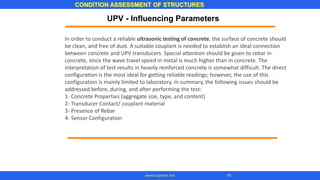
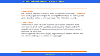
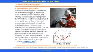
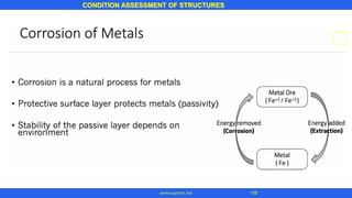
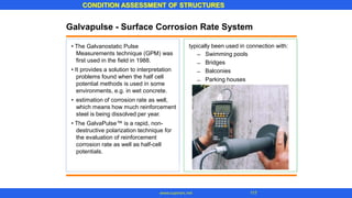
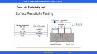
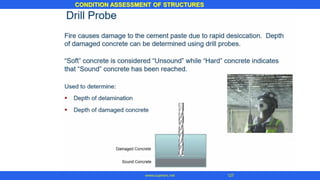
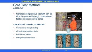
Concrete Resistivity test
The Measurement Principle
Where
a is probe spacing [cm]
V is measured potential [V]
I is the current applied [A]
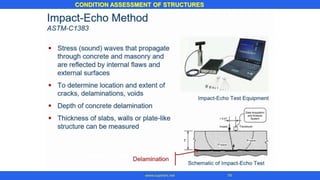
• measure the electrical resistivity of
concrete or rock in a non-destructive
test.
A current is applied to the two outer
probes, with the difference measured
by the two inner probes.
In concrete material with high electrical
resistivity the corrosion process will be
slow compared to concrete with low
resistivity in which the current can
easily pass between anode and
cathode areas
•
•](https://image.slidesharecdn.com/ilovepdfmerged-201011062732/85/62-_-123-320.jpg)


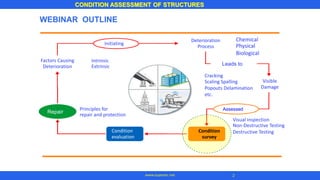
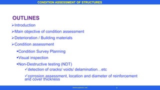
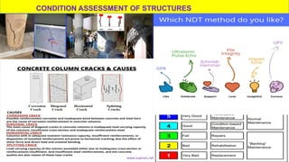
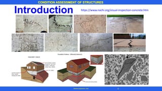
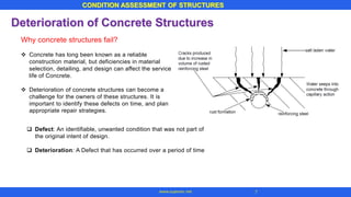
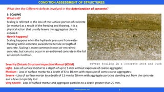
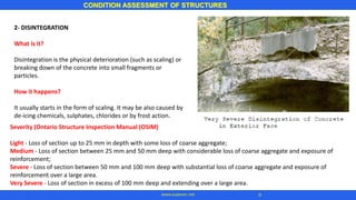
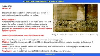
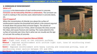
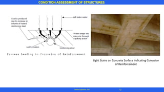
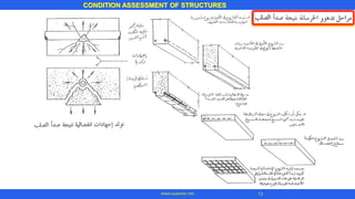
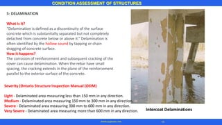
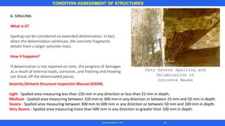
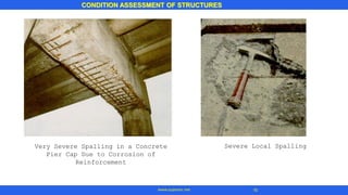
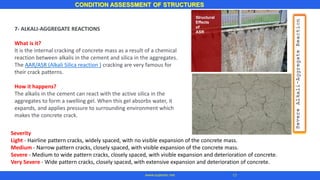
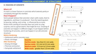
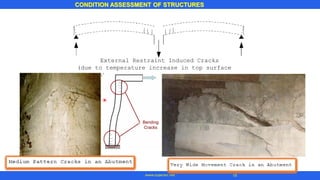
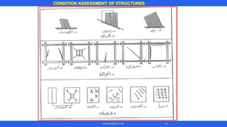
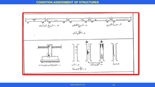
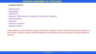
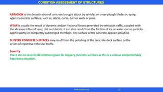
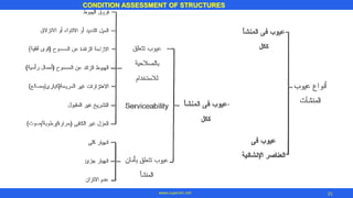
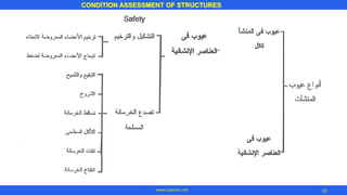
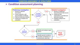
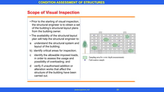
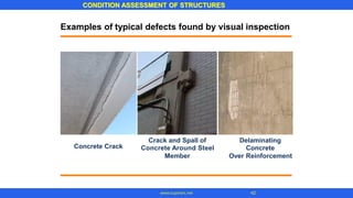
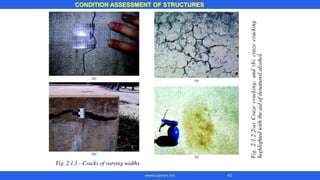
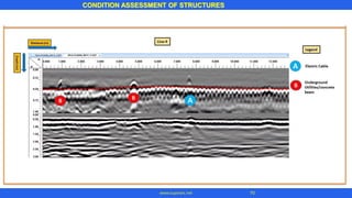
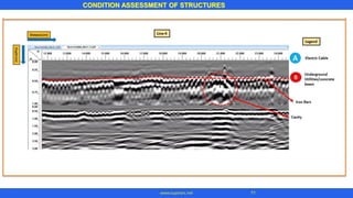
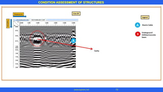
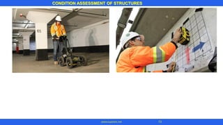
The document discusses condition assessment of structures through visual inspection and non-destructive testing. It outlines the main types of deterioration in concrete structures like scaling, cracking, corrosion of reinforcement, and delamination. The causes and severity levels of each type of deterioration are explained. The document also discusses the steps involved in a condition assessment, including planning, visual inspection, non-destructive testing, analysis and evaluation to determine the repair requirements.


