Downloaded 2,738 times
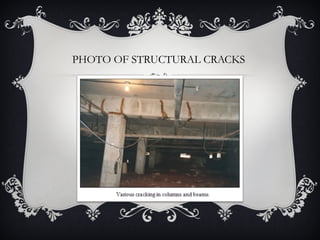
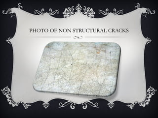


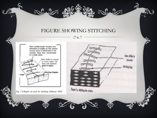

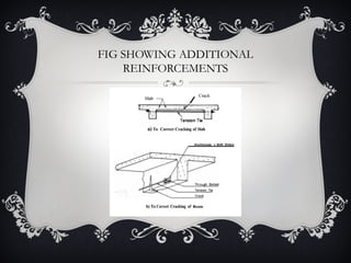


This project case study addresses the causes, classifications, and remedial measures for building cracks. Cracks are categorized into structural and non-structural, caused by various factors such as overloading, thermal movement, and ground movements. Effective repair methods were discussed, including epoxy injection, stitching, and additional reinforcements to mitigate crack-related issues in construction.


