![ASSIGNMENT ECM 530
NorazlinbtMohdRazali[2009297322] EE240 5A.
ECM530 -----20/12/2011
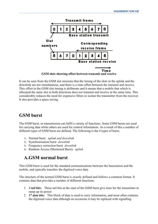
GSM slot structure and multiple access scheme
GSM uses a combination of both TDMA and FDMA techniques. The FDMA element
involves the division by frequency of the (maximum) 25 MHz bandwidth into 124 carrier
frequencies spaced 200 kHz apart as already described.
The carriers are then divided in time, using a TDMA scheme. This enables the different users
of the single radio frequency channel to be allocated different times slots. They are then able
to use the same RF channel without mutual interference. The slot is then the time that is
allocated to the particular user, and the GSM burst is the transmission that is made in this
time.
Each GSM slot, and hence each GSM burst lasts for 0.577 mS (15/26 mS). Eight of these
burst periods are grouped into what is known as a TDMA frame. This lasts for approximately
4.615 ms (i.e.120/26 ms) and it forms the basic unit for the definition of logical channels.
One physical channel is one burst period allocated in each TDMA frame.
There are different types of frame that are transmitted to carry different data, and also the
frames are organised into what are termed multiframes and superframes to provide overall
synchronisation.
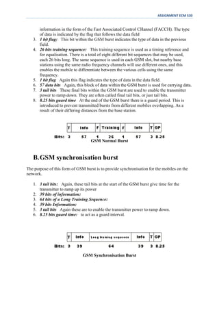
GSM slot structure
These GSM slot is the smallest individual time period that is available to each mobile. It has a
defined format because a variety of different types of data are required to be transmitted.
Although there are shortened transmission bursts, the slots is normally used for transmitting
148 bits of information. This data can be used for carrying voice data, control and
synchronisation data.](https://image.slidesharecdn.com/burst-120105231457-phpapp02/85/Burst-1-320.jpg)
![ASSIGNMENT ECM 530
NorazlinbtMohdRazali[2009297322] EE240 5A.
ECM530 -----20/12/2011
GSM slot structure and multiple access scheme
GSM uses a combination of both TDMA and FDMA techniques. The FDMA element
involves the division by frequency of the (maximum) 25 MHz bandwidth into 124 carrier
frequencies spaced 200 kHz apart as already described.
The carriers are then divided in time, using a TDMA scheme. This enables the different users
of the single radio frequency channel to be allocated different times slots. They are then able
to use the same RF channel without mutual interference. The slot is then the time that is
allocated to the particular user, and the GSM burst is the transmission that is made in this
time.
Each GSM slot, and hence each GSM burst lasts for 0.577 mS (15/26 mS). Eight of these
burst periods are grouped into what is known as a TDMA frame. This lasts for approximately
4.615 ms (i.e.120/26 ms) and it forms the basic unit for the definition of logical channels.
One physical channel is one burst period allocated in each TDMA frame.
There are different types of frame that are transmitted to carry different data, and also the
frames are organised into what are termed multiframes and superframes to provide overall
synchronisation.
GSM slot structure
These GSM slot is the smallest individual time period that is available to each mobile. It has a
defined format because a variety of different types of data are required to be transmitted.
Although there are shortened transmission bursts, the slots is normally used for transmitting
148 bits of information. This data can be used for carrying voice data, control and
synchronisation data.](https://image.slidesharecdn.com/burst-120105231457-phpapp02/75/Burst-1-2048.jpg)

This document discusses the GSM slot structure and multiple access scheme. It explains that GSM uses a combination of TDMA and FDMA, dividing carriers by frequency and then dividing time using TDMA. Each GSM slot lasts 0.577ms and 8 slots are grouped into a 4.615ms TDMA frame. There are different types of frames and bursts used to carry various data and provide synchronization. The document then describes the structure and purpose of normal, synchronization, frequency correction, and random access bursts.