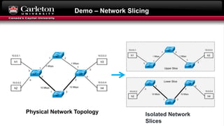
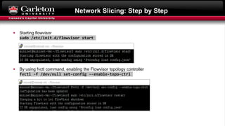
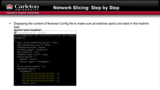
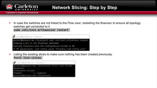
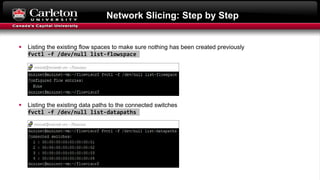
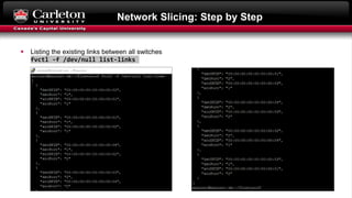
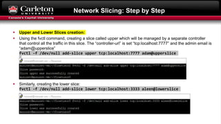
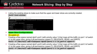
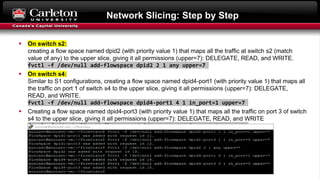
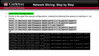
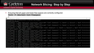
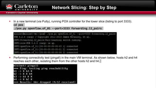
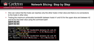
5G Network Slicing Using Mininet
Mohammed Abuibaid
Fall 2019
Email:
m.a.abuibaid@gmail.com
Outline
Background
Generic 5G Network Slicing Framework
FlowVisor
Demo – Network Slicing
Background - One Size Does Not Fit All
Multiple Applications 
Different QOS requirements 
Same authentication, mobility, reliability, delay, and QOS
 COMPROMISES 
4G Radio Acess Network 4G Evolved Packet Core Network
Generic Mobile Network Slicing Framework
 Heterogeneous set of infrastructure components
like data centers, routers and base stations.
E.g. Rogers Communications
 Creation of each network slice according to service
instance requests coming from the upper layer.
 Enabling Technologies: SDN and NFV
 NFs: Firewall, MMEs, S-GWs, Load balancer
Foukas, X.; Patounas, G.; Elmokashfi, A.; Marina, M. K. (2017). "Network Slicing in 5G: Survey and
Challenges" (PDF). IEEE Communications Magazine. 55 (5): 94–100.
 MVNOs: e.g. Fido, Chatr Mobile, and SimplyConnect.
 All shares the underlying physical network and it
provides a unified vision of the service requirements.
FlowVisor
 Special Purpose OpenFlow Controller
 Enables Network Virtualization
 Transparent proxy between OpenFlow switches
and multiple controllers
 Creates rich slice of network resources
 Delegates control of each slice to a different
controller
 It intercepts the messages
FlowVisor Implemented on OpenFlow
What is FlowVisor?
Demo – Network Slicing
Isolated Network
Slices
Physical Network Topology
Network Slicing: Step by Step
 In the main VM terminal, running the custom topology except operating the POX controller which will be
started after slice configurations.
sudo python Network_Topology.py
 In a new VM terminal (via Putty), making sure that the flowvisor is stopped.
sudo /etc/init.d/flowvisor stop
 Generating the flowvisor Config.json file.
fvconfig generate /etc/flowvisor/config.json
Network Slicing: Step by Step
 Starting flowvisor
sudo /etc/init.d/flowvisor start
 By using fvctl command, enabling the Flowvisor topology controller
fvctl -f /dev/null set-config --enable-topo-ctrl
Network Slicing: Step by Step
 Displaying the content of flowvisor Config file to make sure all switches dpid’s are listed in the fvadmin
field
fvctl get-config
Network Slicing: Step by Step
 In case the switches are not linked to the Flow visor, restarting the flowvisor to ensure all topology
switches get connected to it
sudo /etc/init.d/flowvisor restart
 Listing the existing slices to make sure nothing has been created previously.
fvctl list-slices
Network Slicing: Step by Step
 Listing the existing flow spaces to make sure nothing has been created previously
fvctl -f /dev/null list-flowspace
 Listing the existing data paths to the connected switches
fvctl -f /dev/null list-datapaths
Network Slicing: Step by Step
 Listing the existing links between all switches
fvctl -f /dev/null list-links
Network Slicing: Step by Step
 Upper and Lower Slices creation:
 Using the fvctl command, creating a slice called upper which will be managed by a separate controller
that control all the traffic in this slice. The “controller-url” is set “tcp:localhost:7777” and the admin email is
“adam@upperslice”
fvctl -f /dev/null add-slice upper tcp:localhost:7777 adam@upperslice
 Similarly, creating the lower slice:
fvctl -f /dev/null add-slice lower tcp:localhost:3333 aleen@lowerslice
Network Slicing: Step by Step
 Listing the existing slices to make sure that the upper and lower slices are correctly created.
fvctl list-slices
 Upper Slice Configurations:
 On switch s1:
Creating a flow space named dpid1-port1 (with priority value 1) that maps all the traffic on port 1 of switch
s1 to the upper slice, giving it all permissions (upper=7): DELEGATE, READ, and WRITE.
fvctl -f /dev/null add-flowspace dpid1-port1 1 1 in_port=1 upper=7
 Creating a flow space named dpid1-port3 (with priority value 1) that maps all the traffic on port 3 of switch
s1 to the upper slice, giving it all permissions (upper=7): DELEGATE, READ, and WRITE
fvctl -f /dev/null add-flowspace dpid1-port3 1 1 in_port=3 upper=7
Network Slicing: Step by Step
 On switch s2:
creating a flow space named dpid2 (with priority value 1) that maps all the traffic at switch s2 (match
value of any) to the upper slice, giving it all permissions (upper=7): DELEGATE, READ, and WRITE.
fvctl -f /dev/null add-flowspace dpid2 2 1 any upper=7
 On switch s4:
Similar to S1 configurations, creating a flow space named dpid4-port1 (with priority value 1) that maps all
the traffic on port 1 of switch s4 to the upper slice, giving it all permissions (upper=7): DELEGATE,
READ, and WRITE.
fvctl -f /dev/null add-flowspace dpid4-port1 4 1 in_port=1 upper=7
 Creating a flow space named dpid4-port3 (with priority value 1) that maps all the traffic on port 3 of switch
s4 to the upper slice, giving it all permissions (upper=7): DELEGATE, READ, and WRITE
fvctl -f /dev/null add-flowspace dpid4-port3 4 1 in_port=3 upper=7
Network Slicing: Step by Step
 Lower Slice Configurations:
 Similar to the upper flow spaces configurations, creating the following flow spaces on switches s1, s3,
and s4.
fvctl -f /dev/null add-flowspace dpid1-port2 1 1 in_port=2 lower=7
fvctl -f /dev/null add-flowspace dpid1-port4 1 1 in_port=4 lower=7
fvctl -f /dev/null add-flowspace dpid3 3 1 any lower=7
fvctl -f /dev/null add-flowspace dpid4-port2 4 1 in_port=2 lower=7
fvctl -f /dev/null add-flowspace dpid4-port4 4 1 in_port=4 lower=7
Network Slicing: Step by Step
 Ensuring that all upper and lower flow spaces are correctly configured.
fvctl -f /dev/null list-flowspace
Network Slicing: Step by Step
 In a new terminal (via Putty), running a POX controller for the upper slice listing on port 7777.
cd pox
./pox.py openflow.of_01 --port=7777 forwarding.l2_pairs
 Performing connectivity test (pingall) in the main VM terminal. As shown below, only hosts h1 and h3
reaches each other, isolating them from the other hosts h2 and h4.
Network Slicing: Step by Step
 In a new terminal (via Putty), running POX controller for the lower slice (listing to port 3333).
cd pox
./pox.py openflow.of_01 --port=3333 forwarding.l2_pairs
 Performing connectivity test (pingall) in the main VM terminal. As shown below, hosts h2 and h4
reaches each other, isolating them from the other hosts h2 and h4.
Network Slicing: Step by Step
 One can notice that the hosts can reaches only the other hosts in their slice and there is no connections
to the hosts in other slice.
 Testing the maximum achievable bandwidth between hosts h1 and h3 for the upper slice and between h2
and h4 for the lower slice using the command iperf.
iperf h1 h3
iperf h2 h4
5G Network Slicing Using Mininet

5G Network Slicing Using Mininet

  • 1.
    5G Network SlicingUsing Mininet Mohammed Abuibaid Fall 2019 Email: m.a.abuibaid@gmail.com
  • 2.
    Outline Background Generic 5G NetworkSlicing Framework FlowVisor Demo – Network Slicing
  • 3.
    Background - OneSize Does Not Fit All Multiple Applications  Different QOS requirements  Same authentication, mobility, reliability, delay, and QOS  COMPROMISES  4G Radio Acess Network 4G Evolved Packet Core Network
  • 4.
    Generic Mobile NetworkSlicing Framework  Heterogeneous set of infrastructure components like data centers, routers and base stations. E.g. Rogers Communications  Creation of each network slice according to service instance requests coming from the upper layer.  Enabling Technologies: SDN and NFV  NFs: Firewall, MMEs, S-GWs, Load balancer Foukas, X.; Patounas, G.; Elmokashfi, A.; Marina, M. K. (2017). "Network Slicing in 5G: Survey and Challenges" (PDF). IEEE Communications Magazine. 55 (5): 94–100.  MVNOs: e.g. Fido, Chatr Mobile, and SimplyConnect.  All shares the underlying physical network and it provides a unified vision of the service requirements.
  • 5.
    FlowVisor  Special PurposeOpenFlow Controller  Enables Network Virtualization  Transparent proxy between OpenFlow switches and multiple controllers  Creates rich slice of network resources  Delegates control of each slice to a different controller  It intercepts the messages FlowVisor Implemented on OpenFlow What is FlowVisor?
  • 6.
    Demo – NetworkSlicing Isolated Network Slices Physical Network Topology
  • 7.
    Network Slicing: Stepby Step  In the main VM terminal, running the custom topology except operating the POX controller which will be started after slice configurations. sudo python Network_Topology.py  In a new VM terminal (via Putty), making sure that the flowvisor is stopped. sudo /etc/init.d/flowvisor stop  Generating the flowvisor Config.json file. fvconfig generate /etc/flowvisor/config.json
  • 8.
    Network Slicing: Stepby Step  Starting flowvisor sudo /etc/init.d/flowvisor start  By using fvctl command, enabling the Flowvisor topology controller fvctl -f /dev/null set-config --enable-topo-ctrl
  • 9.
    Network Slicing: Stepby Step  Displaying the content of flowvisor Config file to make sure all switches dpid’s are listed in the fvadmin field fvctl get-config
  • 10.
    Network Slicing: Stepby Step  In case the switches are not linked to the Flow visor, restarting the flowvisor to ensure all topology switches get connected to it sudo /etc/init.d/flowvisor restart  Listing the existing slices to make sure nothing has been created previously. fvctl list-slices
  • 11.
    Network Slicing: Stepby Step  Listing the existing flow spaces to make sure nothing has been created previously fvctl -f /dev/null list-flowspace  Listing the existing data paths to the connected switches fvctl -f /dev/null list-datapaths
  • 12.
    Network Slicing: Stepby Step  Listing the existing links between all switches fvctl -f /dev/null list-links
  • 13.
    Network Slicing: Stepby Step  Upper and Lower Slices creation:  Using the fvctl command, creating a slice called upper which will be managed by a separate controller that control all the traffic in this slice. The “controller-url” is set “tcp:localhost:7777” and the admin email is “adam@upperslice” fvctl -f /dev/null add-slice upper tcp:localhost:7777 adam@upperslice  Similarly, creating the lower slice: fvctl -f /dev/null add-slice lower tcp:localhost:3333 aleen@lowerslice
  • 14.
    Network Slicing: Stepby Step  Listing the existing slices to make sure that the upper and lower slices are correctly created. fvctl list-slices  Upper Slice Configurations:  On switch s1: Creating a flow space named dpid1-port1 (with priority value 1) that maps all the traffic on port 1 of switch s1 to the upper slice, giving it all permissions (upper=7): DELEGATE, READ, and WRITE. fvctl -f /dev/null add-flowspace dpid1-port1 1 1 in_port=1 upper=7  Creating a flow space named dpid1-port3 (with priority value 1) that maps all the traffic on port 3 of switch s1 to the upper slice, giving it all permissions (upper=7): DELEGATE, READ, and WRITE fvctl -f /dev/null add-flowspace dpid1-port3 1 1 in_port=3 upper=7
  • 15.
    Network Slicing: Stepby Step  On switch s2: creating a flow space named dpid2 (with priority value 1) that maps all the traffic at switch s2 (match value of any) to the upper slice, giving it all permissions (upper=7): DELEGATE, READ, and WRITE. fvctl -f /dev/null add-flowspace dpid2 2 1 any upper=7  On switch s4: Similar to S1 configurations, creating a flow space named dpid4-port1 (with priority value 1) that maps all the traffic on port 1 of switch s4 to the upper slice, giving it all permissions (upper=7): DELEGATE, READ, and WRITE. fvctl -f /dev/null add-flowspace dpid4-port1 4 1 in_port=1 upper=7  Creating a flow space named dpid4-port3 (with priority value 1) that maps all the traffic on port 3 of switch s4 to the upper slice, giving it all permissions (upper=7): DELEGATE, READ, and WRITE fvctl -f /dev/null add-flowspace dpid4-port3 4 1 in_port=3 upper=7
  • 16.
    Network Slicing: Stepby Step  Lower Slice Configurations:  Similar to the upper flow spaces configurations, creating the following flow spaces on switches s1, s3, and s4. fvctl -f /dev/null add-flowspace dpid1-port2 1 1 in_port=2 lower=7 fvctl -f /dev/null add-flowspace dpid1-port4 1 1 in_port=4 lower=7 fvctl -f /dev/null add-flowspace dpid3 3 1 any lower=7 fvctl -f /dev/null add-flowspace dpid4-port2 4 1 in_port=2 lower=7 fvctl -f /dev/null add-flowspace dpid4-port4 4 1 in_port=4 lower=7
  • 17.
    Network Slicing: Stepby Step  Ensuring that all upper and lower flow spaces are correctly configured. fvctl -f /dev/null list-flowspace
  • 18.
    Network Slicing: Stepby Step  In a new terminal (via Putty), running a POX controller for the upper slice listing on port 7777. cd pox ./pox.py openflow.of_01 --port=7777 forwarding.l2_pairs  Performing connectivity test (pingall) in the main VM terminal. As shown below, only hosts h1 and h3 reaches each other, isolating them from the other hosts h2 and h4.
  • 19.
    Network Slicing: Stepby Step  In a new terminal (via Putty), running POX controller for the lower slice (listing to port 3333). cd pox ./pox.py openflow.of_01 --port=3333 forwarding.l2_pairs  Performing connectivity test (pingall) in the main VM terminal. As shown below, hosts h2 and h4 reaches each other, isolating them from the other hosts h2 and h4.
  • 20.
    Network Slicing: Stepby Step  One can notice that the hosts can reaches only the other hosts in their slice and there is no connections to the hosts in other slice.  Testing the maximum achievable bandwidth between hosts h1 and h3 for the upper slice and between h2 and h4 for the lower slice using the command iperf. iperf h1 h3 iperf h2 h4