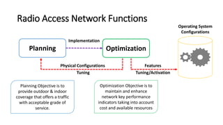
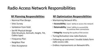
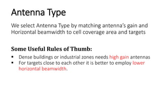
BTM543 Space-time Wireless Communications Systems
KOCAELI UNIVERSITY
Graduate School of
Natural and Applied Sciences
Prepared By: Mohammed ABUIBAID
Email: m.a.abuibaid@gmail.com
Submitted to: Dr. Halil YİĞİT
Electronic and Communication Engineering
RF Antenna Planning
AcademicYear
2015/2016
Agenda
1. Radio Access Network Functions
2. Radio Access Network Responsibilities
3. Antenna Configuration Requirements
4. RF Antenna Planning
5. Nominal Radio Plan For Kocaeli University
Radio Access Network Functions
Planning Optimization
Physical Configurations
Tuning
Implementation
Features
Tuning/Activation
Operating System
Configurations
Planning Objective is to
provide outdoor & indoor
coverage that offers a traffic
with acceptable grade of
service.
Optimization Objective is to
maintain and enhance
network key performance
indicators taking into account
cost and available resources
Radio Access Network Responsibilities
RF Planning Responsibilities
− Nominal Plan Design
− Sites Survey
− Validation from field
− Set RF Physical design
(Site Structure, Azimuth, Height, Tilt,
Cables type)
− Frequency Plan
− Neighbor Plan
− Sites Acceptance
RF Optimization Responsibilities
− Maintaining Network KPIs:
• Accessibility: Users’ ability to access the network
• Retainability: Users’ ability to successfully
to continue their connections
• Integrity: Keeping the quality of the service
− Tuning/Activation new radio features
− Following up costumers’ trouble tickets form
radio access side.
− Endless improvements on Network KPIs.
Antenna Configuration Requirements
- Antenna Diversity:
- Isolation of 30 dB: (for TX-to-TX and
TX-to-RX relationships)
 Radiation Patterns must not be
distorted by obstacles or reflections
near the antenna.
 Reducing antenna height by 50% will
reduce average received signal by 6 dB
The values here are valid for 850 MHz, 1900 MHz,
and collocated 850/1900 MHz systems only.
 Antennas must be Separated from each other to achieve:
Space Diversity
 The horizontal separation needed for
the antennas is dependent on the
required diversity gain.
 The vertical separation requires
approximately five times the
horizontal value in order to get the
same diversity gain.
 Generally 1 m is required for each 10
m in height above the ground to
achieve 3-6 dB gain in Rx level.
Polarization Diversity
 The diversity gain obtained from polarization
diversity is slightly less then the gain from
space diversity.
 A dual polarized antenna offers very low
correlation between the two received signals,
but the power reception of each branch is
slightly better with space diversity.
 In interference-limited environments, the low
correlation obtained by polarization diversity
is advantageous.
 Due to slightly different propagation
characteristics for different kinds of
polarization, the downlink from a ±45 degree
dual polarized antenna suffers from about 1.5
dB extra loss compared to two vertically
polarized antennas.
Isolation
 Needed to avoid distortion due to intermodulation
 Need to fulfill these isolation values
− TX – RX isolation > 30 dB
− TX – TX isolation > 30 dB
 Horizontal physical separation
requirements
− 30 dB isolation: 11.5 λ
− 800 MHz: 3 m
− 1900 MHz: 1.8 m
 Vertical separation requirement
for antenna is 0.2 meter
RF Antenna Planning
Suppose a cellular operator use
the following antennas for Radio
Sites Planning:
 KATHREIN 742 264
 KATHREIN 742 266
 KATHREIN 800 10122
 KATHREIN 800 10121
How to determine the antenna
physical configurations in each
radio site ?
 Antenna Type
 Antenna Azimuth
 Antenna E-Tilt
 Antenna Height
KATHREIN742 264
KATHREIN 742 266
KATHREIN800 10122
KATHREIN800 10121
Internal View to RF
Antennas
 900/1800 MHz dual band
 ∓𝟒𝟓° cross-polarization diversity
 16 elements /array
Nominal Radio Plan For Kocaeli University
The terrain nature in Umuttepe Campus is so
complex
Proposed Solution: Green Field Tower (40 m)
 Tower of height 40m can overcome the
terrain difficulties but it may cause
interference on sites in the proximity.
 Low density population around the
university so a tolerable amount of
interference maybe caused on other sites.
Three Towers for
three operators
Cell A
Cell B
Cell C
Cell D
SiteCoverageArea
We select Antenna Type by matching antenna’s gain and
Horizontal beamwidth to cell coverage area and targets
Antenna Type
Some Useful Rules of Thumb:
 Dense buildings or industrial zones needs high gain antennas
 For targets close to each other it is better to employ lower
horizontal beamwidth.
YEMEKHANE
YURTLAR
HUKUK FAK.
EDEBİYAT B BLOK
EĞITIM FAK.
YURTLAR
𝟔𝟓 °
Cell A Coverage Targets (K64)
KABAOĞLU KÖY
LOJMANLARLOJMANLAR
YURTLAR
LOJMANLAR
Cell B Coverage Targets (K66)
𝟔𝟓°
YABANCI DILLER
SPOR YÜKSEKOKULU
SPOR ALANI
YÜZME HAVUZU
ÖĞRENCI YURDU
Cell C Coverage Targets (K22)
𝟖𝟖°
EDEBİYAT A BLOK
KÜTÜPHANE
OTOPARK & DURAK
REKTÖRLÜK
MÜH. A-BLOK
KOU HASTANESI
TIP FAK.
TEKNOLOJI FAK
Cell C Coverage Targets (K66)
Cell A: e-Tilt Calculation
379
+ 40
– 368
---------
51 m 451 m
𝜃 = 𝑡𝑎𝑛
51
451
−1
≈ 6. 5°
Cell A: e-Tilt Calculation
379
+ 40
– 368
---------
51 m 451 m
𝜽 ≈ 𝟔. 𝟓°
14°
Cell A: e-Tilt Calculation
379
+ 40
– 368
---------
51 m 451 m
𝜽 = 𝟔. 𝟓°
14°
Cell A: e-Tilt Calculation (Criteria 1)
379
+ 40
– 368
---------
51 m 451 m
𝜽 = 𝟔. 𝟓° + 𝟕° = 𝟏𝟑. 𝟓°
14°
Cell A: e-Tilt Calculation (Criteria 2)
Antennas Physical Configuration
Cell Name Cell A Cell B Cell C Cell D
Azimuth 48 128 204 337
E-tilt 13.5 ?? ?? ??
Antenna Type K64 K66 K22 K66
Coverage
Target
Yurtlar, MÜH. B-blok
EĞİTİM, HUKUK,
EDEBİYAT, Yemekhane
Kabaoğlu Köy,
Lojmanlar, Yurtlar
Öğrenci Yurdu,
Yabanci Diller,
Yüzme Havuzu, Spor
Alani, Spor
Yüksekokulu
Kou Hastanesi, Tıp
Fak., Teknoloji Fak,
Teknoloji Fak
Edebiyat A Blok,
Otopark & Durak,
Rektörlük,
Kütüphane, Müh. A-
blok
Mohammed Abuibaid
Live & Breathe Wireless

RF Antenna Planning

  • 1.
    BTM543 Space-time WirelessCommunications Systems KOCAELI UNIVERSITY Graduate School of Natural and Applied Sciences Prepared By: Mohammed ABUIBAID Email: m.a.abuibaid@gmail.com Submitted to: Dr. Halil YİĞİT Electronic and Communication Engineering RF Antenna Planning AcademicYear 2015/2016
  • 2.
    Agenda 1. Radio AccessNetwork Functions 2. Radio Access Network Responsibilities 3. Antenna Configuration Requirements 4. RF Antenna Planning 5. Nominal Radio Plan For Kocaeli University
  • 3.
    Radio Access NetworkFunctions Planning Optimization Physical Configurations Tuning Implementation Features Tuning/Activation Operating System Configurations Planning Objective is to provide outdoor & indoor coverage that offers a traffic with acceptable grade of service. Optimization Objective is to maintain and enhance network key performance indicators taking into account cost and available resources
  • 4.
    Radio Access NetworkResponsibilities RF Planning Responsibilities − Nominal Plan Design − Sites Survey − Validation from field − Set RF Physical design (Site Structure, Azimuth, Height, Tilt, Cables type) − Frequency Plan − Neighbor Plan − Sites Acceptance RF Optimization Responsibilities − Maintaining Network KPIs: • Accessibility: Users’ ability to access the network • Retainability: Users’ ability to successfully to continue their connections • Integrity: Keeping the quality of the service − Tuning/Activation new radio features − Following up costumers’ trouble tickets form radio access side. − Endless improvements on Network KPIs.
  • 5.
    Antenna Configuration Requirements -Antenna Diversity: - Isolation of 30 dB: (for TX-to-TX and TX-to-RX relationships)  Radiation Patterns must not be distorted by obstacles or reflections near the antenna.  Reducing antenna height by 50% will reduce average received signal by 6 dB The values here are valid for 850 MHz, 1900 MHz, and collocated 850/1900 MHz systems only.  Antennas must be Separated from each other to achieve:
  • 6.
    Space Diversity  Thehorizontal separation needed for the antennas is dependent on the required diversity gain.  The vertical separation requires approximately five times the horizontal value in order to get the same diversity gain.  Generally 1 m is required for each 10 m in height above the ground to achieve 3-6 dB gain in Rx level.
  • 7.
    Polarization Diversity  Thediversity gain obtained from polarization diversity is slightly less then the gain from space diversity.  A dual polarized antenna offers very low correlation between the two received signals, but the power reception of each branch is slightly better with space diversity.  In interference-limited environments, the low correlation obtained by polarization diversity is advantageous.  Due to slightly different propagation characteristics for different kinds of polarization, the downlink from a ±45 degree dual polarized antenna suffers from about 1.5 dB extra loss compared to two vertically polarized antennas.
  • 8.
    Isolation  Needed toavoid distortion due to intermodulation  Need to fulfill these isolation values − TX – RX isolation > 30 dB − TX – TX isolation > 30 dB  Horizontal physical separation requirements − 30 dB isolation: 11.5 λ − 800 MHz: 3 m − 1900 MHz: 1.8 m  Vertical separation requirement for antenna is 0.2 meter
  • 9.
    RF Antenna Planning Supposea cellular operator use the following antennas for Radio Sites Planning:  KATHREIN 742 264  KATHREIN 742 266  KATHREIN 800 10122  KATHREIN 800 10121 How to determine the antenna physical configurations in each radio site ?  Antenna Type  Antenna Azimuth  Antenna E-Tilt  Antenna Height
  • 10.
  • 11.
  • 12.
  • 13.
  • 14.
    Internal View toRF Antennas  900/1800 MHz dual band  ∓𝟒𝟓° cross-polarization diversity  16 elements /array
  • 15.
    Nominal Radio PlanFor Kocaeli University The terrain nature in Umuttepe Campus is so complex Proposed Solution: Green Field Tower (40 m)  Tower of height 40m can overcome the terrain difficulties but it may cause interference on sites in the proximity.  Low density population around the university so a tolerable amount of interference maybe caused on other sites. Three Towers for three operators
  • 16.
    Cell A Cell B CellC Cell D SiteCoverageArea
  • 17.
    We select AntennaType by matching antenna’s gain and Horizontal beamwidth to cell coverage area and targets Antenna Type Some Useful Rules of Thumb:  Dense buildings or industrial zones needs high gain antennas  For targets close to each other it is better to employ lower horizontal beamwidth.
  • 18.
    YEMEKHANE YURTLAR HUKUK FAK. EDEBİYAT BBLOK EĞITIM FAK. YURTLAR 𝟔𝟓 ° Cell A Coverage Targets (K64)
  • 19.
  • 20.
    YABANCI DILLER SPOR YÜKSEKOKULU SPORALANI YÜZME HAVUZU ÖĞRENCI YURDU Cell C Coverage Targets (K22) 𝟖𝟖°
  • 21.
    EDEBİYAT A BLOK KÜTÜPHANE OTOPARK& DURAK REKTÖRLÜK MÜH. A-BLOK KOU HASTANESI TIP FAK. TEKNOLOJI FAK Cell C Coverage Targets (K66)
  • 22.
    Cell A: e-TiltCalculation
  • 23.
    379 + 40 – 368 --------- 51m 451 m 𝜃 = 𝑡𝑎𝑛 51 451 −1 ≈ 6. 5° Cell A: e-Tilt Calculation
  • 24.
    379 + 40 – 368 --------- 51m 451 m 𝜽 ≈ 𝟔. 𝟓° 14° Cell A: e-Tilt Calculation
  • 25.
    379 + 40 – 368 --------- 51m 451 m 𝜽 = 𝟔. 𝟓° 14° Cell A: e-Tilt Calculation (Criteria 1)
  • 26.
    379 + 40 – 368 --------- 51m 451 m 𝜽 = 𝟔. 𝟓° + 𝟕° = 𝟏𝟑. 𝟓° 14° Cell A: e-Tilt Calculation (Criteria 2)
  • 27.
    Antennas Physical Configuration CellName Cell A Cell B Cell C Cell D Azimuth 48 128 204 337 E-tilt 13.5 ?? ?? ?? Antenna Type K64 K66 K22 K66 Coverage Target Yurtlar, MÜH. B-blok EĞİTİM, HUKUK, EDEBİYAT, Yemekhane Kabaoğlu Köy, Lojmanlar, Yurtlar Öğrenci Yurdu, Yabanci Diller, Yüzme Havuzu, Spor Alani, Spor Yüksekokulu Kou Hastanesi, Tıp Fak., Teknoloji Fak, Teknoloji Fak Edebiyat A Blok, Otopark & Durak, Rektörlük, Kütüphane, Müh. A- blok
  • 28.
    Mohammed Abuibaid Live &Breathe Wireless

Editor's Notes

  • #15 A dual-polarized antenna is an antenna device with two arrays within the same physical unit. The two arrays can be designed and oriented in different ways as long as the two polarization planes have equal performance with respect to gain and radiation patterns. Ex. Arrays in ±45 degree slant orientation.